MBD Simulation on a Piston Assembly
AIM: MBD Motion analysis of Piston Assembly.
OBJECTIVE: Analysing and comparing Linear displacement of piston for different wrist pin position.
Key Points:
- Brief of Piston Assembly and its application
- Design of Piston head, crank and connection rod.
- Initial setup for motion study and Calculation
- Plotting different parameters and Comparison
- Conclusion
- References
Piston Assembly:
There are numerous mechanical motions which are used in Industrial applications. Piston-crank assembly is a type of slider crank mechanism. This converts rotary motion of crank to reciprocating motion of Piston or vice-versa.
We will be considering Piston-crank mechanism for single cylinder engine for this project.
Application:
This combination finds its application in many areas of automotive industry mainly inside Engine blocks. Most prime movers use piston-crank assembly as primary mechanism to convert energy into mechanical motion.
With the help of Piston-crank assembly, we can convert reciprocating motion of piston to rotary motion of crank which in turn powers the transmission system to move the vehicle. Optimum design of Piston-crank assembly plays important role in defining optimum engine efficiency.
Working of a Simple IC engine:
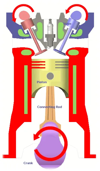
IC engine is an Internal Combustion engine which contains several components namely cylinder head, Piston, Gudgeon pin, connecting rod, crank, crank shaft. Piston is constrained inside the cylinder such as it can reciprocate along its vertical axis. Connecting rod works as a link between piston and crank mechanism. Crank shaft is at the bottom of the assembly which helps converting reciprocating motion of Piston into rotary motion at output part.
Air + Fuel mixture is burned inside cylinder head. The energy generated, creates a piston stroke which in turn rotates crank at the bottom thereby converting piston linear motion to crank rotary motion.
We will be considering piston-crank assembly in the project, to simulate and calculate the linear displacement of piston for different cases.
Design of Piston-crank Assembly components:
Design of Piston:
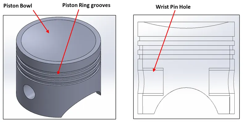
Design of a Piston contains “Piston Bowl” which is primarily subjected to all the pressure and thermal energy generated during combustion. Piston is generally made of low carbon steel or aluminium due to is excellent heat transfer property and low weight applications.
Piston also has grooves for “Piston ring” which works as a sealing between cylinder inside surface and piston outer surface. It also helps lubricating piston during reciprocating motion.
Design of Wrist Pin (Gudgeon Pin):
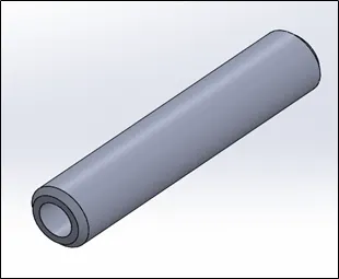
Wrist pin joins the connecting road with Piston head. Pin is mostly affected by thermal expansions during heat transfer process. It is also subjected to higher stress during frequent directional motion between piston and connecting rod.
Wrist Pin is generally made of Steel which surface is hardened to improves wear resistance.
Design of Connecting Rod:
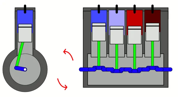
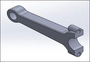
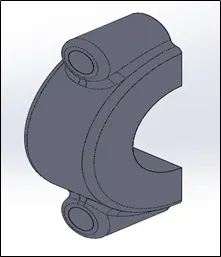
Connecting road is the link between piston and crank shaft. It goes under repetitive forces such as compression during piston downward movement, Tensile when moving upward and shearing due to angle between piston and crank pin. These forces are directly related to RPM.
Design of Crank:
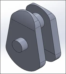
Crank is designed such a way that it converts reciprocating motion of piston to rotary motion with minimum loss of energy. For that, construction is purposefully designed with mass balance. Sometimes flywheel is also used to balance mass at the end. Crank shaft is subjected to torsion and bending stress during motion.
Setting up assembly of Piston-crank:
For the sake of the project, we will consider crank as prime mover which inputs rotary motion. For assembly, firstly constrain crank in the assembly environment such as it can only rotate around its horizontal axis.
After that, insert connecting rod to be concentric with crank shaft and constrain its relative motion with respect to crank.
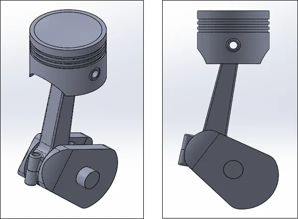
Finally, we will insert piston and wrist pin. Piston and wrist pin are concentric with each other and those two are aligned with connecting rod so as to achieve desired motion. Motion of piston is constrained in such a way that its vertical axis is in line with vertical axis of crank. The desired motion is such that piston should only have reciprocating motion in only one direction when the crank is rotated.
The final output is shown below.
Setting up the simulation:
After completing assembly, we will setup a motion study. Considering rotating motion input at crank, we will plot the linear motion of piston.
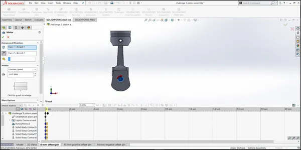
First, apply “Motor” to the front face in crank shaft which shows crank will rotate in Clock wise direction. Give the value of 2000 RPM.
Secondly, we will need to define contacts between related bodies. Give appropriate contact.
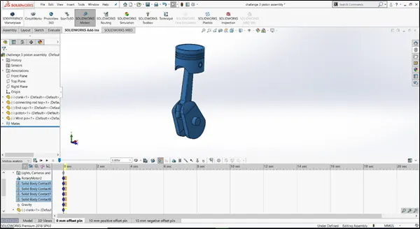
Note: “Contact body” option helps in simulating real time behaviour of components. For each pair of contact bodies, we will be using same material i.e. (Steel (dry)).
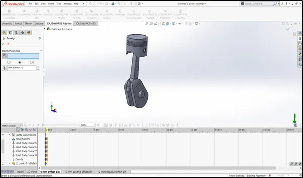
Third, we will add gravity to the model. In image below, gravity is given in Y direction.
For smooth motion calculation and to capture maximum displacement of piston at each rotational degree, we will use “precise contact” option and 7200 fps option.
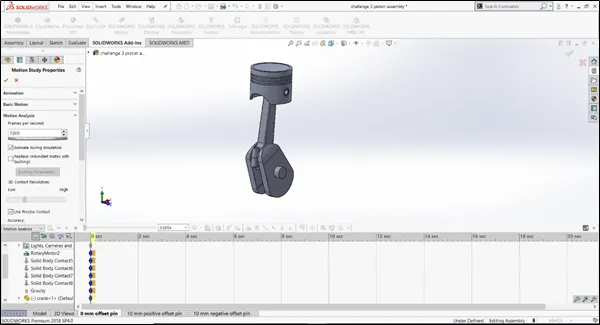
Final Motion study parameters:
- Crank input: 2000 rpm
- Frame rate: 7200 fps
- Use “precise contact”
- Motion study Duration: 0.2 sec.
Plotting and comparison for different cases:
Below cases are considered for plotting purpose and comparison.
- Wrist pin 0 mm offset from crank axis
- Wrist pin 10 mm positive offset
- Wrist pin 10 mm negative offset.
Case 1: Wrist pin 0 mm offset from crank axis
In this case, as described, wrist pin is constrained in such a way that its vertical axis is inline with crank axis. The case is shown in image.
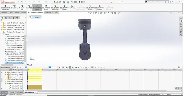
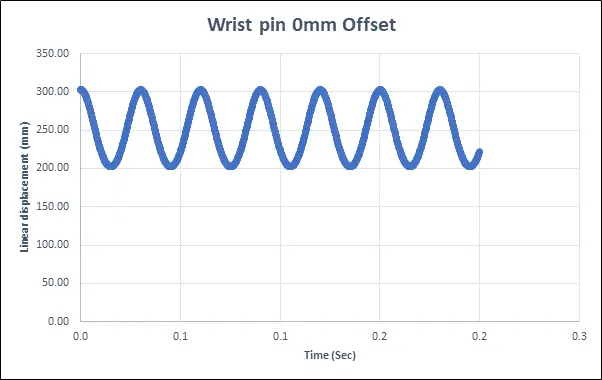
After completing motion study, we have plotted graph for linear displacement of Piston (mm).
Case 1: 0 mm offset, Linear displacement of piston
Case 2: Wrist pin 10mm positive offset
In this case, as described, wrist pin is constrained in such a way that its vertical axis is 10mm offset with crank axis. The case is shown in image.
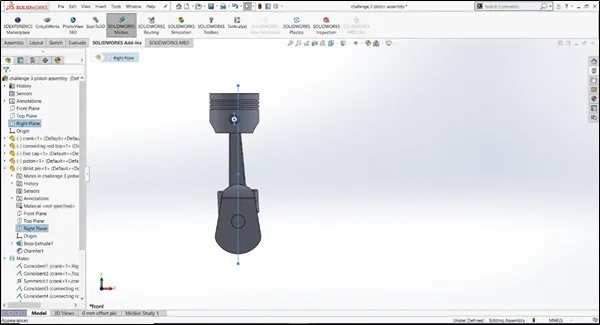
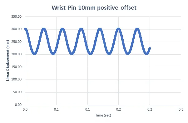
After completing motion study, we have plotted graph for linear displacement of Piston (mm).
Case 2: 10 mm positive offset, Linear displacement of piston
Case 3: Wrist pin 10mm negative offset
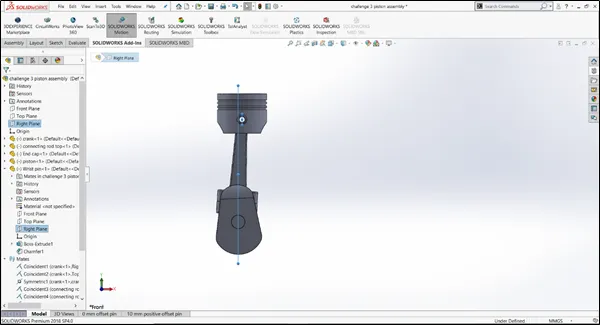
In this case, as described, wrist pin is constrained in such a way that its vertical axis is 10mm negative offset with crank axis. The case is shown in image.
After completing motion study, we have plotted graph for linear displacement of Piston (mm).
Case 3: 10 mm negative offset, Linear displacement of piston
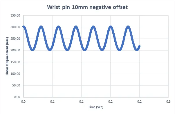
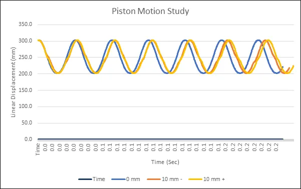
After plotting these graphs, they look quite similar that the linear displacement of piston is between 200 to 300 mm for each case. Initially the plots look similar but the difference lies between completion of each cycle with respect to time.
Thereby superimposing those graphs in single plot, we can easily identify the difference.
Conclusion:
- The very first observation from the given study, is that frequency of displacement of piston with respect to crank rotation at a given time frame, increases as we offset the axis from crank axis. As we move from Negative to positive offset of wrist pin, the linear displacement is retained for longer period of time which eventually helps in less effort to rotate crank. Thus, from the perspective of IC engine working, setting up wrist pin in positive offset from crank axis, helps in achieving more efficiency.
- Secondly, if we reduce fps value in motion study analysis, output plot is not much accurate as we may miss the displacement values for each degree of crank rotation.
- Thirdly, Maximum and minimum values of linear displacements are not affected by offsetting of pin.
Animation:
- Piston-crank assembly : MBD Simulation of Piston-crank Assembly
References: