Draft Analysis on Fan Cover
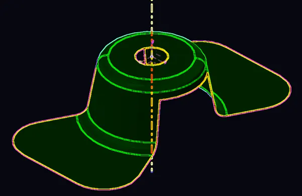
AIM: Draft Analysis on Fan Cover Using CATIA V5.
OBJECTIVE: Generating draft analysis report on a fan cover using tooling axis generation by bisecting method.
Key Points:
- What is draft? How it is useful in designing a plastic component?
- What is draft analysis?
- Tooling Axis (Bisecting method)
- Generating draft analysis on component
- Conclusion
What is draft? How it is useful in designing a plastic component?
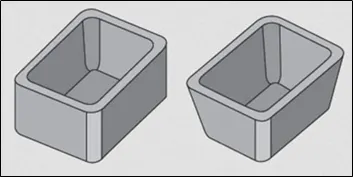
In engineering, draft is the amount of taper for moulded or cast parts perpendicular to the parting line.
When developing parts for plastic injection molding, applying draft (or a taper) to the faces of the part is critical to improving the moldability of your part. Without it, parts run the risk of poor cosmetic finishes, and may bend, break, or warp due to molding stresses caused by the plastic cooling. Equally important, an absence of draft may prevent parts from ejecting from the mold, damaging not only the parts, but possibly the mold itself—a costly and time-consuming detour.
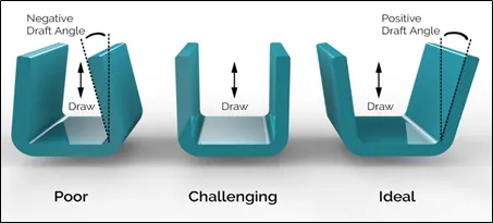
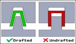
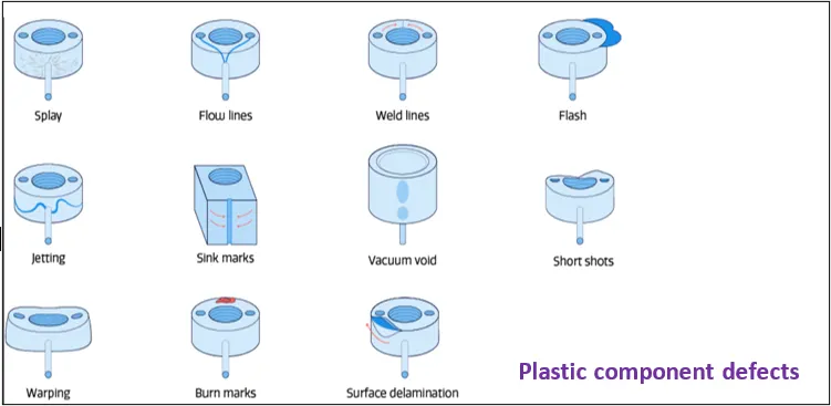
Here are four ways that draft can improve part moldability.
Draft Early
Ignoring draft early in the design process is a common mistake that occurs at prototyping stage with 3D printing and CNC machining processes where draft is not required. Layer-by-layer method in which 3D-printed parts are built, and during CNC prototyping there is no importance of part ejection as it is a purely a molding consideration.
But if a prototype stage design will eventually move to injection molding, it is befitting to design draft into parts from the very beginning. Draft may alter the form and fit of a part during assembly and its overall aesthetic, so designing in draft, even when it’s not technically needed, can help you avoid any surprises such as costly redesigns and additional prototype development.
Follow the Rules
The truth is no single draft angle can be applied to all part designs. Factors like wall thickness, material selection, ejection, shrink rates, finish/texture, wall depth, and manufacturing capabilities all come into play.
When designing a part, a general rule of thumb is 1 degree of draft per 1 inch of cavity depth, but that can change with the aforementioned factors. Try following these general guidelines:
- 5 degrees on all vertical faces is strongly advised (which is costly as well).
- 1 to 2 degrees works very well in most situations.
- 3 degrees is minimum for a shutoff (metal sliding on metal).
- 3 ~5 degrees or more is required for light to heavy texture surfaces
Implement a Core-CavityApproach
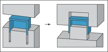
Adding draft to an enclosure can create issues if it isn’t applied correctly. When applying draft to the inside and outside walls, design these walls parallel to each other. Consider a core-cavity approach to design as this opens up the mold cavity and core for polishing, accelerates manufacturing speed and, in general, brings added ease during the molding process. Also, it facilitates in the mold that make venting, ejection, mold finishing, and manufacturing easier.
Factor in Surface Finish
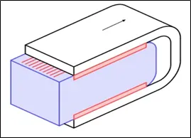
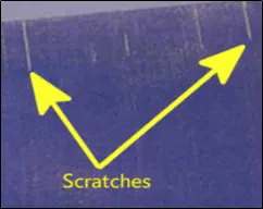
With a lack of mold draft, the part would drag on the moulded surface while the mold opens and ejects the parts, creating surface finish scratches. Since all thermoplastics shrink while they cool in the mold, a massive amount of surface tension is created, preventing the part from releasing cleanly during ejection. This tension creates small scratches in the polished surface, and it’s even worse for textured surfaces—if draft is missing.
Texture is applied many different ways, but they all create micro undercuts from pitting the mold surface. The texture on the mold walls would lock the part into place, if not drafted properly. By applying a degree of draft, the part is allowed to move a short distance before the mold shrink is able to clear the micro undercuts, and ultimately the concern of mold drag or scratches on the part is minimized.
What is Draft Analysis?
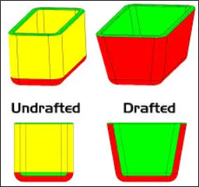
This type of analysis is performed based on colour ranges identifying zones on the analysed element where the deviation from the draft direction at any point, corresponds to specified values. The draft analysis button within CATIA V5 will help you quickly gather the draft angle on multiple surfaces without the need for tedious manual measurements.
Tooling Axis (Bisecting Method):
Tooling Axis is an imaginary axis in which direction the tooling operation is performed. In Injection molding, the direction in which the mold is opened / closed, is called tooling direction.
The draft angle, which also plays a major role in plastic component design, is decided with reference to the main tooling axis of the component.
Bisecting method for generating Main Tooling axis of component.
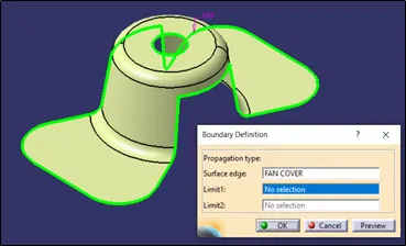
- The given Input will be CLASS A Surface of the component, which we need to verify for boundary discontinuities.
2. Then we can make a dummy tooling axis for reference by approximating from part geometry. Observing component from different directions, we can assume the dummy tooling axis location.
That would also help as first step of bisecting method.
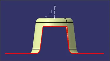
Assuming Tooling Axis in X direction, it is clear that the hole in the component will not be cleared by X direction tooling axis. Below image shows the view assuming tooling axis in X direction.
Similarly, if we assume, tooling axis in Y direction, the hole as well as the side wall drafts are not easy to clear by Y direction tooling axis. Below image shows the view assuming tooling axis in Y direction.
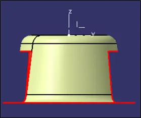
Now the Z direction tooling axis, clears the hole on top as well as the drafts on sidewalls of the component. It is evident from below image that Z direction should be the Tooling axis of the given component.
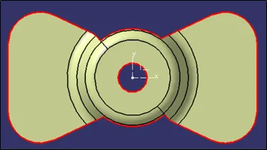
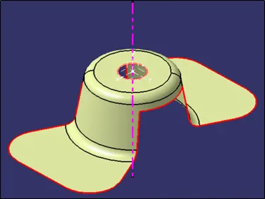
3. Now that the tooling direction is defined, we can make temporary tooling axis for the part as shown below. Taking the hole profile as a reference, below image shows temporary tooling axis in Z direction.
Taking it as a reference, we can proceed to define actual tooling axis using bisecting method.
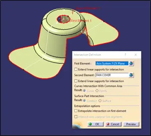
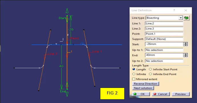
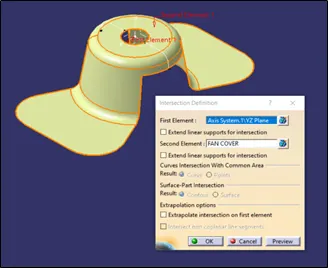
4. Bisecting method will use reference lines created from different intersections of component with reference planes. Firstly, take intersection of component with XZ plane to get profile as a reference.
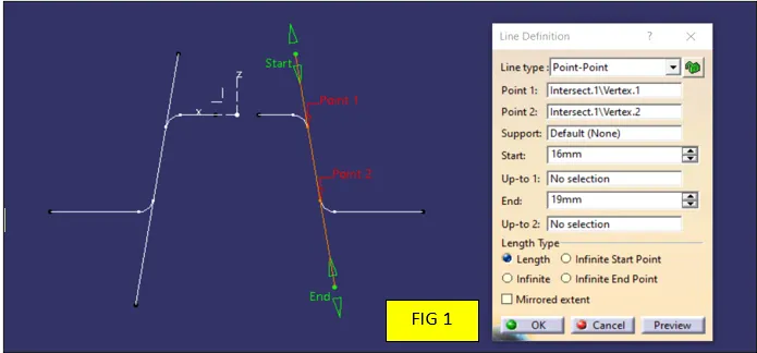
Create two lines parallel to profile as shown in Fig 1. After creating two parallel lines, Create a bisecting line from those two lines Fig 2.
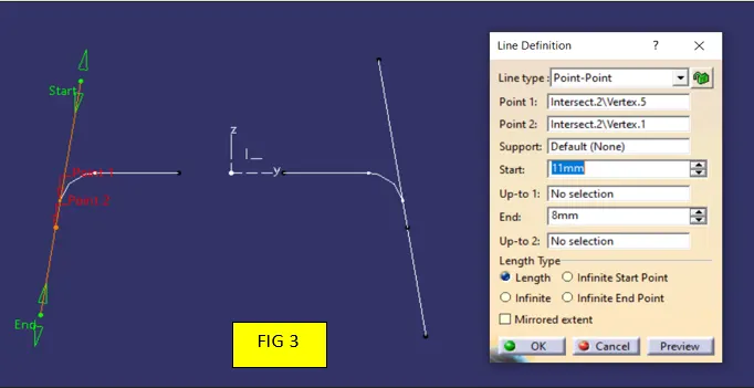
Now, take intersection of component with YZ plane to get profile as a reference. Create two lines parallel to profile as shown in Fig 3.
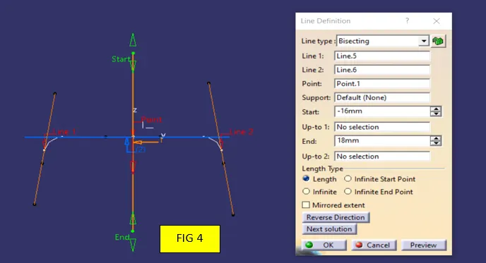
After creating two parallel lines, Create a bisecting line from those two lines Fig 4.
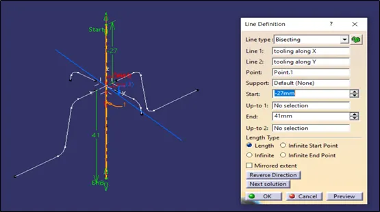
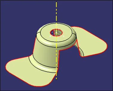
5. We have two lines that are resulted from the intersections. Use them to create a bisecting line. That would be the main tooling axis for the given component.
Yellow one shows the main tooling axis of the component. Depending upon complexity of components, it is possible that we get tooling axis out of the component area.
It is not necessary to get tooling axis on the component.
Generating draft analysis on component:
Draft analysis gives you the overall information about draft angles required with reference to main tooling axis of the component. While designing, we could give the draft angles to desired faces to clear the tooling direction. To evaluate given draft angles, we use draft analysis tool in CATIA V5.
Draft analysis steps.
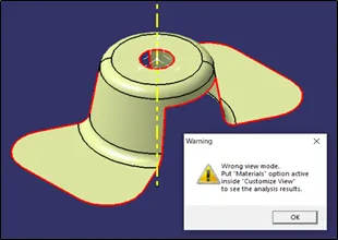
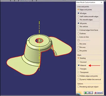
- Material mode plays a vital role in generating draft analysis. The tool calculates draft angles required based upon material properties and behaviour during tooling operation. Not setting up, will give you a warning message.
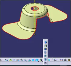
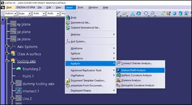
2. After setting material mode, click on “Feature Draft analysis” from Insert menu. A dialogue box will be opened.
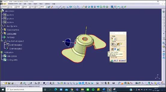
3. Use the compass option from the box, to align the current axis system with main tooling direction. It would create draft analysis with reference to tooling axis.
Carefully align the axis system with main tooling axis and click on the component anywhere to create draft analysis.
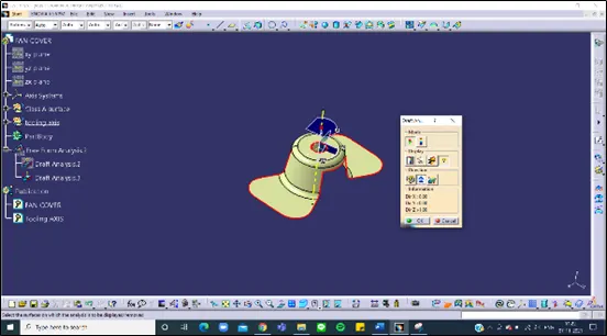
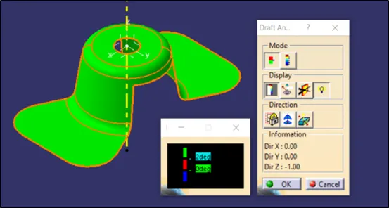
4. There are several options which can be helpful.
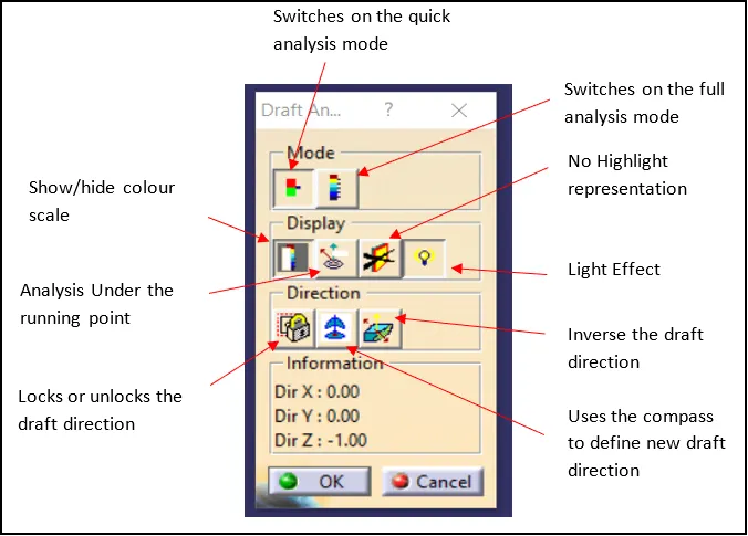
Mode: It has two options where we can set values for colour legends. The first option is shorter legend where the other option is for larger legend options where we can use multiple angle values
to analyse accurate draft angles.
Display: It has four options. First option is to hide/show the colour legend. The third and fourth option is to switch hide/show additional highlights and additional lighting respectively.
Second option is called, analysis under running point. It shows the value of draft at the exact pointer on the component.
Direction: It has three options. Firs is Lock the draft direction. Used to fix the tooling direction once it is fixed with compass.
Second option is compass. It is using the compass to create new tooling direction.
Third option is reverse drafting direction. It simply reverses the draft direction and gives output.
Conclusion:
- Created the Tooling axis using bisecting method.
- Used the main tooling axis for creating draft analysis on the component.
- Insights to Feature draft analysis tool and its options.
Hence, we have successfully created drafting analysis on the Fan Cover using bisecting method for main tooling direction and learnt about importance of draft angle and tooling axis for plastic manufacturing process.
References: