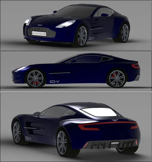
Aston Martin One 77 - Solidworks Surfacing
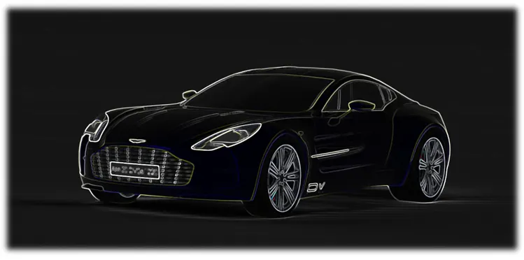
AIM: Modelling Aston Martin One-77 using Solidworks surfacing.
OBJECTIVES:
This project demonstrates various skills on Surface and Solid modelling, generating assembly of parts and rendering them to get a realistic view of the given model.
Report Key Points:
- Introduction to Solidworks
- Solidworks modules
- Part modelling
- Assembly
- Solidworks Add-ins
- Modelling of Aston Martin One-77
- Rendering
- Conclusion
Introduction to Solidworks:
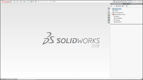
Solidworks is CAD modelling and CAE software from Dessault Systems that provides user with the easy-to-use Graphical user Interface (GUI), Enriched features which are required for Industrial use. First version of Solidworks was “Solidworks 95” that was published in November 1995. This project uses Solidworks 2018 version.
Modelling in Solidworks Initially starts by drawing 2D sketch consisting of lines, points, arcs, splines and other 2D elements. Later these 2D sketches are used to create 3D features having desired shapes. Solidworks also has its Design library which contains pre-defined design templates, Tool Box, 3D contents and material library which keeps updating timely to keep pace with current industry requirements.
|
Fig 1. Solidworks Start-up Page. |
Solidworks modules:
Solidworks was introduced with the aim to provide easy to use interface for the designers who intend to create models which looks realistic and flexible to changes depending upon variety of application.
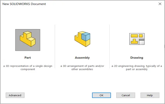
As described earlier, Solidworks is a 3D CAD modelling and CAE software. There are multiple modules for each domain. Initially it has 3 modules to be started with the software.
Part modelling, Assembly and Drafting modules.
|
Fig 2. Solidworks module |
In this project Part modelling and Assembly, both are used. Part modelling is used to create 3D CAD models weather solid or surface. Assembly module is used for creating assembly of created parts.
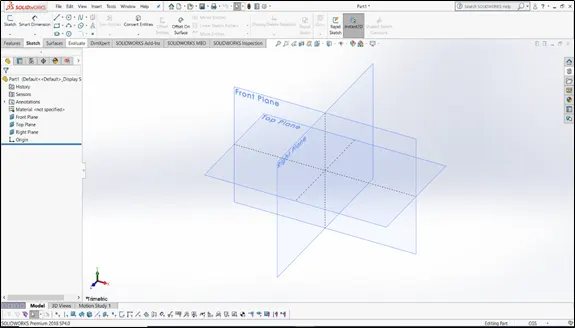
|
Fig 3. Solidworks GUI |
Part module:
As we click on the part module, first we see Solidworks Working Environment. From the Top of the window, there are several things namely Menu bar, Features Ribbon, Feature Tree on the very left section and Solidworks Library on the right most section of the window.
Feature Tree shows steps which we perform during modelling. It also shows Part modelling history, Document properties, Part appearance etc.
Menu bar includes menus which include feature specific commands along with Tools, Windows and Help.
Feature Ribbon is the main portion that we are looking here for.

|
Fig 4. Part module |
As we can see it Ribbon has Tabs Named Features, Sketch, Surfaces, and Solidworks Add-Ins to be named a few. We will be looking briefly into Features, Sketch, and Surface for the sake of project.
Sketch:

|
Fig 5. 2D Sketch |
Sketch is the first most step to start with designing in Solidworks. It has all the tools to create, modify and dimension 2D entities required as per shape. Here in the project for creating surface, “Splines” command is mostly used because of its flexibility to provide desired shape out of the curve. Also it has the option to create 3D sketch under the sketch command, to create sketch in 3D environment.
Features:

|
Fig 6. Creating 3D feature |
Feature Tab is used for creating 3D shapes out of 2D profiled made from sketch. For Boss Extrude, Revolve, Swept, Loft are operation to create 3D shapes. Extrude Cut, revolve cut etc. are operation to remove material as is name suggests. Pattern, Mirror, Rib, Draft are special features required at several stages.
It also has operation to create reference geometry such as planes, Axis, Coordinate System, Point etc. Also, it has options to create projected curves, Composite curves, Spiral like options to directly create the curve.
Surfaces:

|
Fig 7. Surfaces |
Surfaces tab is the most predominantly used tab in this project as our project is purely based on creating surfaces from curves. Same as features tab, it has operation like Extrude surface, Revolve, Loft, Filled Surface etc. We will be diving deep into each operation during next phases of the project description.
Assembly Module:
Similarly, we have Assembly module in Solidworks to create Assembly out of different parts created in part module. Assembly Module looks similar to Part module windows only changes are in Feature Ribbon as shown below. It contains almost similar feature tabs including sketch, 3d editing to modify the existing part design without switching modules.

|
Fig 8. Assembly module |
Assembly:
As in Fig. 8, Assembly Tab in the Ribbon is shown. “Insert components” lets you to add components in the environment. “Mates” operation is used to create individual mates between the parts or features inside the assembly. These two are the most used commands in this project which we will cover in the last part of the report.
Solidworks Add-ins:
Solidworks also supports various other Add ins for different domain such as Rendering, Electric, 3D scan, Motion Study, Wiring diagram, CAE simulation, Mold analysis etc. Solidworks toolbox has the pre-defined library of fasteners, bearings, nuts, washers etc as per different international standards.

|
Fig 9. Solidworks Add-Ins |
We will be using Photoview 360 to render our Aston Martin One 77 (Exciting…!! 😊 )
That’s it for the Introduction part of the Solidworks 2018. Next, we will be exploring the Modelling of Aston Martin One 77, a sports car from British manufacturer Aston Martin in the year 2009.
This sports car provides us with the most interesting subject because of its complex features and tricky surfaces.
So, keep your eyes on the next few pages and enjoy modelling of “Aston Martin One 77”!
FLOW CHART:
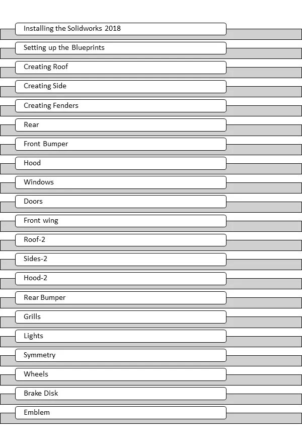
Setting up the Blueprints:
After Installing Solidworks 2018, initiate the process by opening part module. Feature tree is as shown. Make planes visible. The purpose here is to add blueprints in line with the origin of the part environment.
Commands used: Sketch > Sketch Picture (To insert image as sketch on the plane).
Repeat the Sketch Picture Tool to insert All blueprint to all three planes.
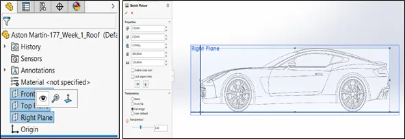
|
Fig 10. Sketch Picture |
Note: Make sure of the blueprints are set so as to keep all of them aligned with origin and images are resized to match the overall dimension of the car i.e. Length, width and Height.
Now, to add rear blueprint, a reference plane is created at the back of length of car. Use Reference Plane to create the plane parallel to front plane. Below images shows the reference plane command and the final blueprint setup.
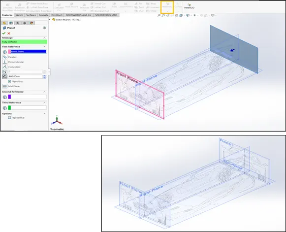
|
Fig 11. Blueprint setup complete |
Designing Roof:
After initial setup of blueprints, designing a roof is a most simple part for the initial stage.
Few new commands are introduced.
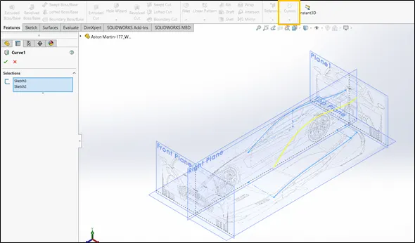
Projected curve: It is used to project a curve by taking 2 sketches as a reference. The two sketches are created on the planes. Projected curve is a resulting curve combining both sketch shapes in 3D environment. In below image, curve in yellow is projected curve of the two sketches (seen in blue).
|
Fig 12. Projected curve |
Repeat the same process to create the curves for roof surface.
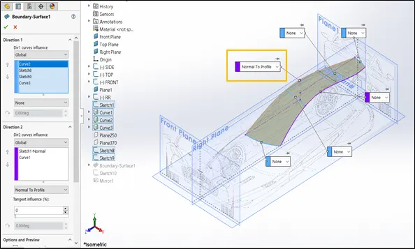
Boundary Surface: It creates surface between 4 boundary curves two of them are in parallel direction and other two are in normal direction to other set. Refer below image for final curves.
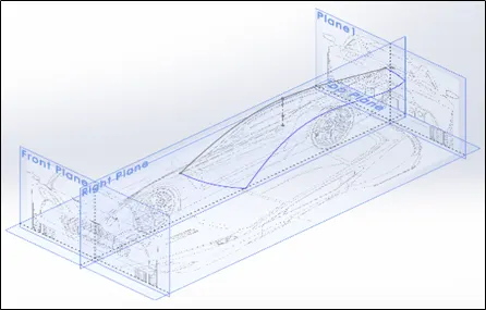
|
Fig 13. Roof boundary |
|
Fig 14. Boundary Surface |
During creating boundary surface, keep the surface normal to right plane because the whole model will be symmetric about right plane.
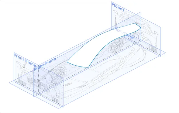
|
Fig 15. Roof |
Designing Side:
This step uses commands used in previous step. Some of the new commands used are described below.
Surface Extrude: It extrudes created sketch. Surface Trim: Trim surface from existing surface.
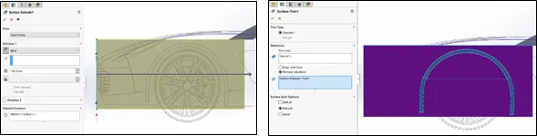
Repeat the same process to create the rear fender as well.
Create the following boundary surface.
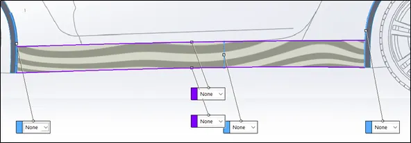
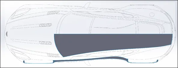
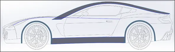
The final outcome is as below.
|
Fig 16. Sides |
Designing Fenders:
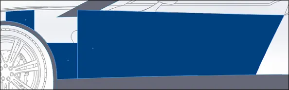
First create the highlighted surfaces as shown below by using projected curves and boundary surface.
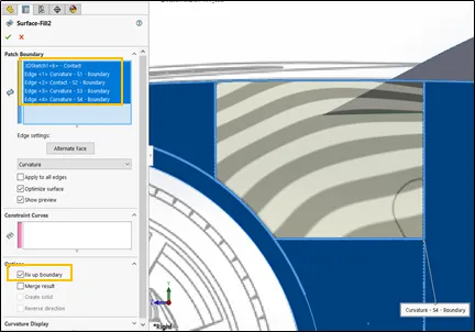
Here one new command is introduced, i.e. Surface fill. It is used to patch a surface between more than 4 sides or using more than 4 curves. Let us see the below image for the use of filled surface.
|
· A surface patch is created using surface fill command between the highlighted curves. · This command uses edges which are connected in such a manner to create a close patch. · Pay Attention to nature of the filled surface with its surrounding surfaces. |
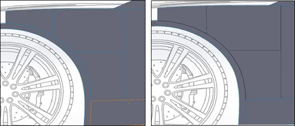
Now again we have used knit surface command to knit the individual surfaces which are tangent or having similar curvature to each other. Two images below show the difference between surface before and after knit operation.
|
Before knit operation Edges in blue shows surfaces are not knitted together. |
After knit operation Dotted edges show knitted surfaces are tangent or having similar curvature. Edges in black are not tangent or doesn’t share curvature. |
Similarly create fender surfaces at the rear of the car and a boundary surface on rear side with the help of projected curves and boundary surface.
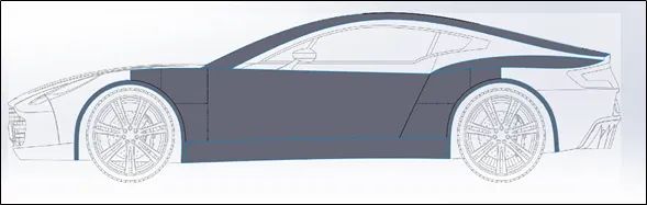
Use the Surface fill command again to fill the patch between rear fender surfaces and knit all surfaces together. Below image shows the final result of the fender.
|
Fig 17. Fender |
Designing Rear:
First created rear surfaces using projected curves and Boundary Surface commands. The Result is shown in the image below.
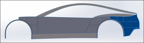
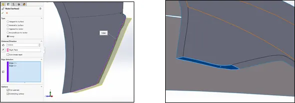
As we look at the very bottom surface connecting rear with arc, it has sharp edge. To remove that sharp edge and to create smooth surface, we have some new commands.
Surface offset: It creates surface offset to existing one. Here we have used it to detach the surface from rest of the body.
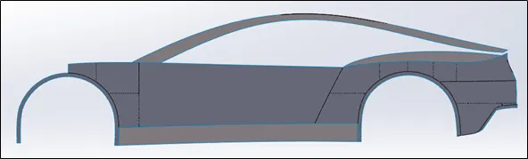
Ruled Surface: It creates the surface from selected edges in the particular direction. Here the use of ruled surface is shown in the image.
Add fillet to the edge, delete the ruled surface. Use trim surface command to delete the bottom Surface. Use boundary surface command to refine the bottom rear edge.
|
Fig 18. Rear of the car |
Designing Front Bumper:
Initially create the following shown surfaces as per described steps. The result is as below.
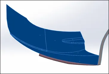
To complete the front bumper, we need to split the bumper surface from rest of the body.
Split: It is used to split surface using existing sketch. The perfect example is shown here, where front bumper is split into two different surfaces.
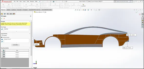
|
Fig 19. Split |
Using the output surface of the split command, offset it from its position to create back of the grills surface. Create the boundary surface to connect offset surface to rest of the body and knit surfaces.
Colour the offset surface in black. The final outcome if the chapter is as follows.
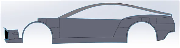
|
Fig 20. Front Bumper |
Designing Hood:
It is the simplest chapter as we have to use the regular commands to create the hood surface.
The result is shown below.
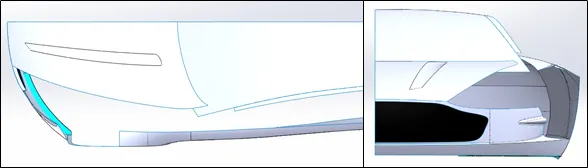
|
Fig 21. Hood |
Designing Windows:
Yet another simple part to create window surfaces. Along with it, created surfaces under the wheel arc to cover the space for Tires. The result is shown below.
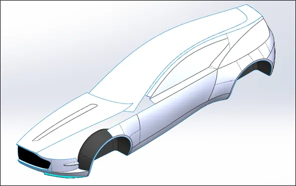
|
Fig 22. Window surface and wheel arc cover |
Designing Door:
Here is the most critical part to design. Because of its complex design, detailed steps are explained.
First step is to create the door surface hinged with the window line near rear arc. Also Design an extruded oval part to design a nice highlight feature on the door surface. Both are shown below.
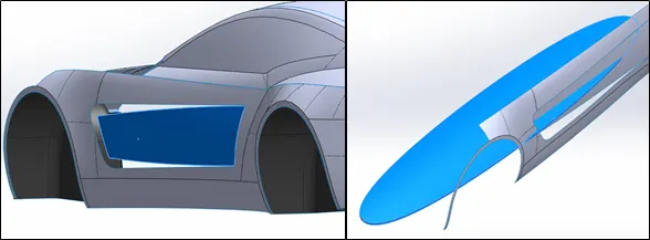
Now remove unwanted geometry and form an oval shaped highlight on the door. Use some fillets to smooth the surfaces. Make the highlighted surfaces using boundary surface option and 3D sketch.
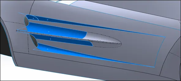
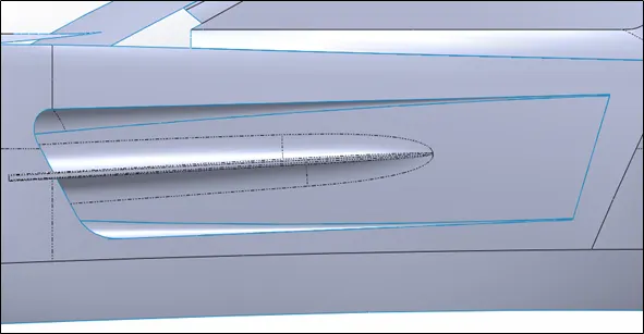
|
Fig 23. Door |
Designing Front Wing:
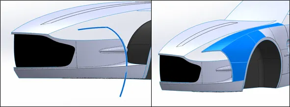
Design of a front wing is a bit critical because it also includes to retain shape of the headlights.
Though the commands used are already covered, the geometry is as shown in the image.
|
Fig 24. Front wing profile |
Fig 25. Front wing profile |
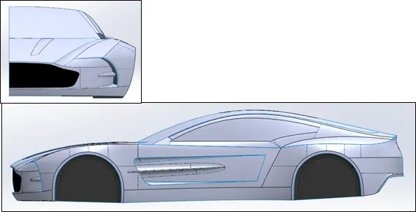
Create the rest of the part for front wing using boundary surface and filled surface command. Result is shown in the other image.
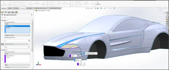
Now, fender and hood are connected with one surface which also helps in building headlamp profile. As we progress with fender connecting the hood, a surface is created that can be replaced to make headlight. The result is as below
|
Fig 26. Headlamp base surface |
|
Fig 27. Final Front wing |
Designing Roof part 2:
Previously we had designed only roof surface. Now we are creating roof surface with actual shape and features. That also included designing of front and rear wind shields.
Here there is a frequent use of split command to split surface according to desired shape. Roof surface is split in to three parts, rear split part is replaced by rear windshield and same is for front.
As we split the surfaces and displace the roof and front surface, we have to create tiny boundary surfaces to connect them with rest of the body. Here is the output before we create the windshield as separate parts.
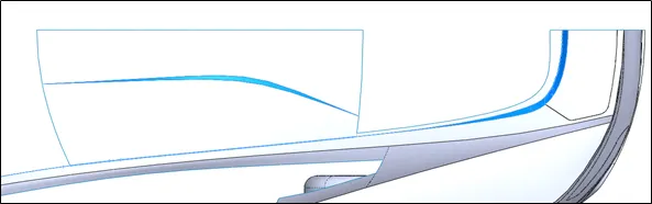
Rear/front surface is opened in a new part model to create windshield out of them.
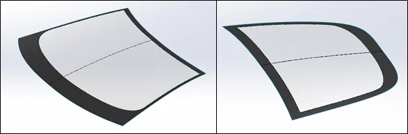
|
Fig 28. Front and rear windshield |
Now as we have several parts to build together, the assembly is created from them. Open a new assembly module and insert body as a first part. The coordinate system of the new assembly and inserted parts, need to be matched relatively. “Mate” command is used. Align front, top and right planes of the assembly to respective planes of the car body part.
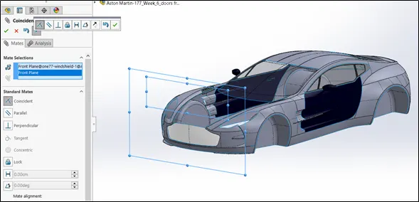
Use “Insert component” Command to insert front and rear windshield to the assembly. Repeat the mate command to align windshields to their respective places.
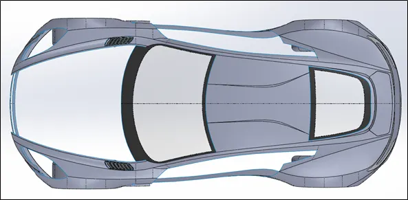
|
Fig 29. Windshield Assembly |
Designing of sides part 2:
Previously we just have created door surface up to some extent. In this module, for modelling detailed door surface, we first detached whole door as a separate body from rest of the body. Use split command again.
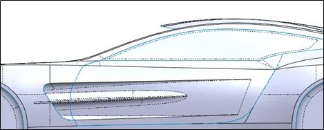
Create small surfaces remaining at window side. Use boundary surface command. Use Zero offset method to detach window surface from the body for the sole purpose of creating side window as separate part same as the windshields.
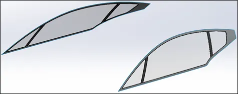
Model the side windows in the separate part file. Output is as below. Assemble windows into assembly file
To create side mirrors, we need door as a separate part. Using split line function, detach shown door profile from car body and insert into new part.
Model door handle and side mirror features into the door part file. Creating a mirror profile is a bit tricky as there are no reference views available. Also, it uses loft surface command along with boundary surface command to create outer profile of mirror. The final output of the door part file is as below.
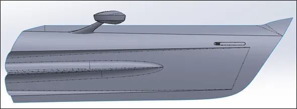
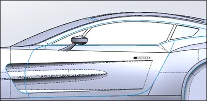
Finally, door is assembled with car body inside assembly file.
|
Fig 30. Door assembly |
Designing hood part 2:
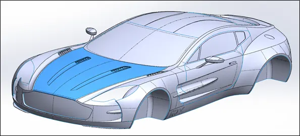
Previous chapter of hood design only shapes hood surface. To model details of the hood, hood is also used as a separate part file. This feature requires a bit of solid modelling. After all the detailing, hood is again assembled into car body. Following image shows final hood assembly.
|
Fig 31. Hood assembly |
Designing rear bumper:
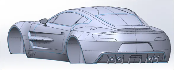
First, created boundary surface for the rear plate as its features are unique. After that, on the same surface, created tail light feature so as to make it easy to model using existing profile curvature. Model the rear spoiler with split and boundary commands.
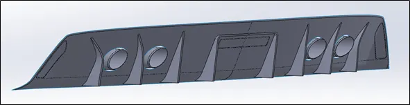
After doing all these, plain rear bumper surface is created and taken into new part to design detailed rear bumper which also includes bumper fins, silencer and reflectors.
Final rear bumper part file is shown below.
|
Fig 32. Rear Bumper |
Assemble rear bumper into car main assembly file.
|
Fig 33. Rear Bumper Assembly |
Designing Grills:
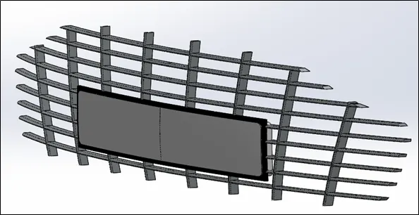
Grills are modelled by taking black front bumper surface as reference as it will also make an outer portion of the grills as a separate part file. Final grill also contains features ready for front number plate.
|
Fig 34. Front Grill |
Designing Headlight:
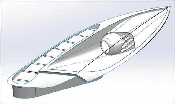
Very first step is to create projected profile of the headlight shape on the existing surface and then take it into separate part to model headlight. This design is among the trickiest designs as there will be no reference to model it quickly. Also, it uses solid modelling features to model light bulb and LEDs around lamp. Final Headlight is shown below.
|
Fig 35. Headlights |
Designing Brake disc and wheels and emblem.
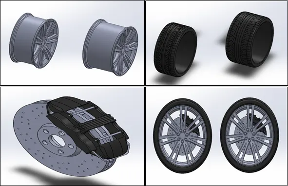
These are the easiest parts to model as they only follow solid modelling approach and fixed dimensions. Front rim, tire and Rear rim, tire both are of different sizes. So they are modelled in separate part files. Disk and disk shoe are also modelled in separate part file.
Rim, tire and disc brakes are assembled in a separate assembly file and inserted in main assembly file as sub-assemblies
All these part files, Final output is shown below.
|
Fig 36. Tire, Rim, Disc Brake and Sub assembly of wheel |
Designing symmetry:
The main body part only contains half portion of the car body. It’s time to mirror the body with respect to right plane.
Here important thing is that, surfaces which are aligned with right planes are tangent, so their mirrored parts must also be tangent to its counterpart.
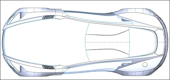
So, get smooth surface between mirrored parts, we need to knit tangent surfaces together. It is the most important and required function to get smooth tangent surfaces along mirrored surfaces.
Here is the symmetry output. Dotted line all along right plane, shows perfectly knitted surfaces. After this, open the main assembly file and let model rebuild itself. End result is pleasant to watch.
|
Fig 37. Symmetric kitted surface |
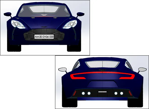
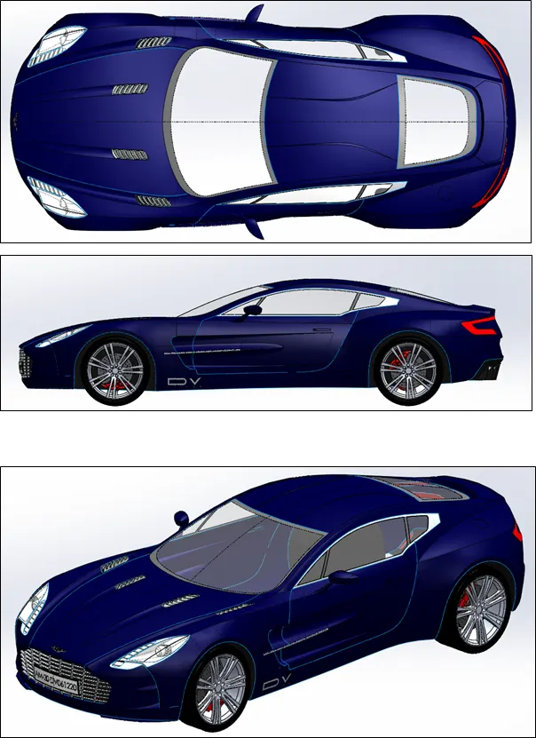
Assemble all the parts along with wheel assembly. Here is the final output of the model.
|
Fig 38. Final Assembly |
Conclusion:
Aston martin One 77 gives us the interesting subject to learn Solidworks surface modelling, as we can see in the images above. Starting from the initial setting up the blueprints, Modelling car body step by step, Using different commands. Along with it, using part modelling to model certain features. Then made a full assembly by adding all the parts together.
Completing assembly ends the Project...!
Rendered the model using Photo view 360.Adding appropriate material to each individual part using diversified material library. Applying suitable appearances. Adding my design Logo on car body at bottom fender surface near front arc, adding number on the front plate are new.
Rendering Images: