MASTER SECTION DEVELOPMENT WITH ENGINEERING FEATURES FOR B PILLAR RH COVER
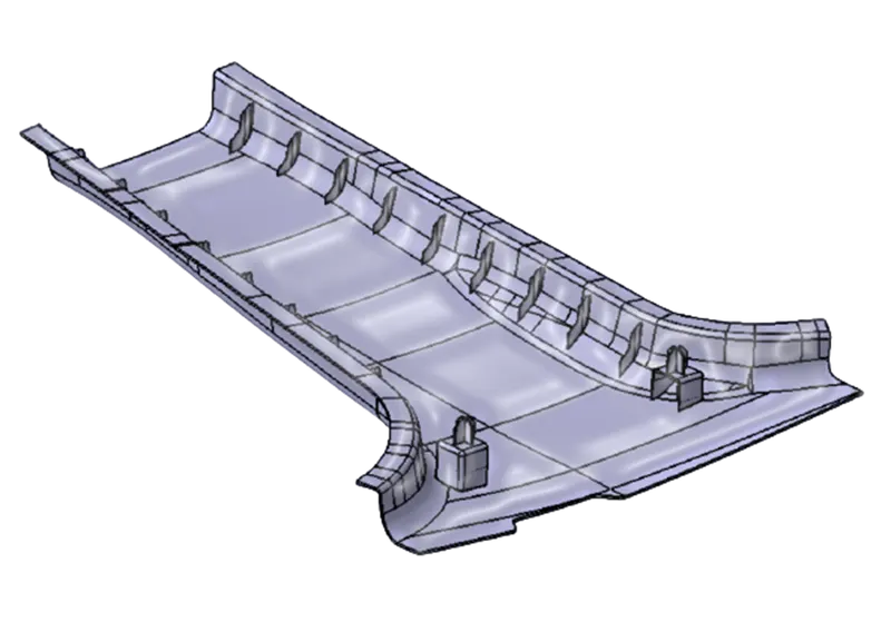
AIM: Master Section Development with Engineering Features for B PILLAR RH Cover Using CATIA V5.
OBJECTIVE: Master Section development, Correcting CLASS A and creating Engineering Fixation Features.
Key Points:
- Master Section and Tooling axis
- Correcting CLASS A from given Master Section as input
- Generating CLASS B surface from given CLASS A
- Generating CLASS C surface from given CLASS A
- Trimming CLASS A and CLASS C
- Generating Final trim for CLASS A, B, C surfaces
- Generating final plastic component from Surface component
- Generating B Side features
- Generating draft analysis on component
- Conclusion
Master Section and Tooling Axis:
Master Section is a c/s profile of the component. It represents main construction of the component. While integrating the part with its surrounding environment in assembly with other parts, Master Section provides fixation strategy for part and its counterparts. Master Sections play major role in assembly and vehicle packaging along with surrounding environment. Here, we are given CLASS A and Master Section of the component.
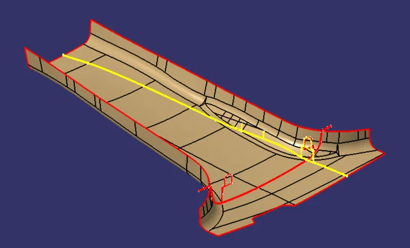
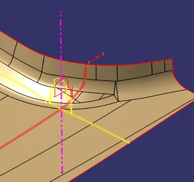
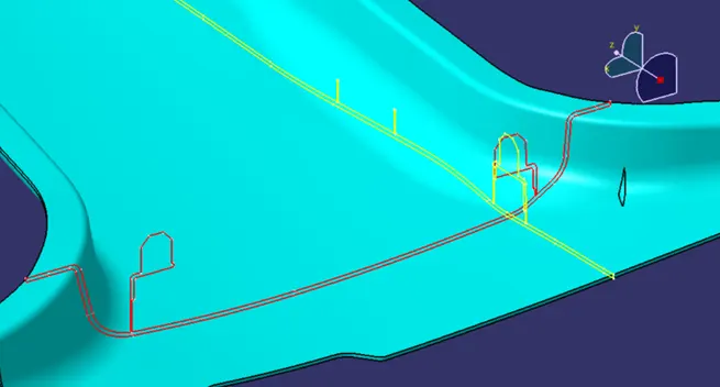
Yellow and Red lines across the component is called Master Section. Upon careful observation, we can identify component’s fixation strategy. That is, there’s provision for Dog-house and Locator pin upon it, at certain position. We can also observe small ribs in the Master Section. It concludes that ribs are located across all sides of the component.
Tooling Axis is an imaginary axis in which direction the tooling operation is performed. In Injection molding, the direction in which the mold is opened / closed, is called tooling direction.
The draft angle, which also plays a major role in plastic component design, is decided with reference to the main tooling axis of the component.
Generating Main Tooling axis of component.
- The given Input will be CLASS A Surface of the component, which we need to verify for boundary discontinuities. Master Section profile suggests that main tooling direction should be ‘Z’ as per manufacturing feasibility. Dog-house profile serves as reference to create Main tooling Axis.
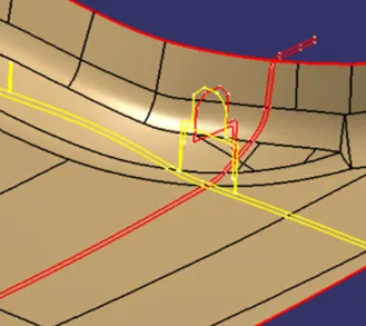
2. Extract the edges from master section and create point between these two lines as indicated.
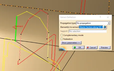
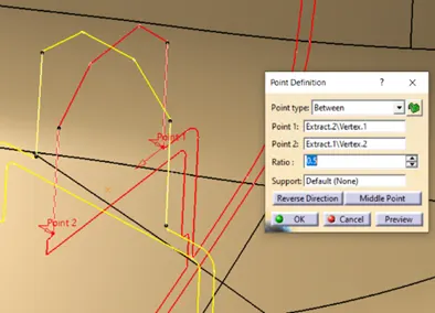
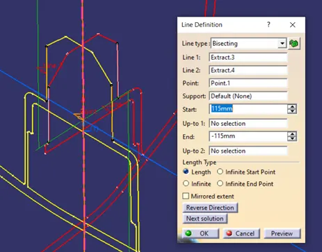
3. Using the point, we can create Main tooling axis along ‘Z’ direction. Use Bisecting Line to create a line between two extracted edges and take point as reference. Bisecting Line as output, gives us main Tooling axis.
Correcting CLASS A from given Master Section as Input:
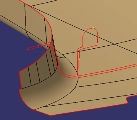
Here, given CLASS A surface needs to be corrected before we process further. Observing Master Section Carefully, we find that CLASS A master section has two extra flanges one each side. We will be creating Flange to LHS and RHS of the CLASS A surface, following given Master Section.
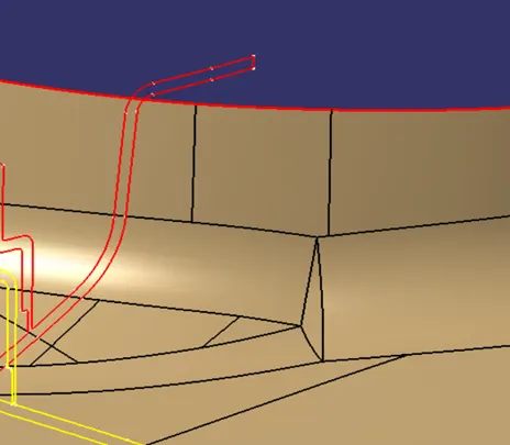
Creating Flange 1
Extracting CLASS A surface to serve as reference. Extract the boundary curve.
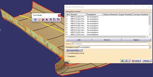
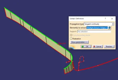
Apply smooth curve command with curvature value of 0.001 mm. Use sweep command to sweep the curve along with given direction to match with Master Section profile.
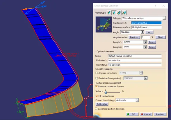
The sweep is created along B side, it is offset to match with CLASS A surface. Offset surface here, creates the discontinuity.
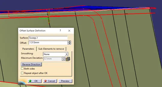
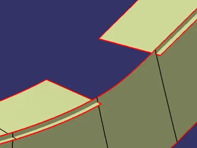
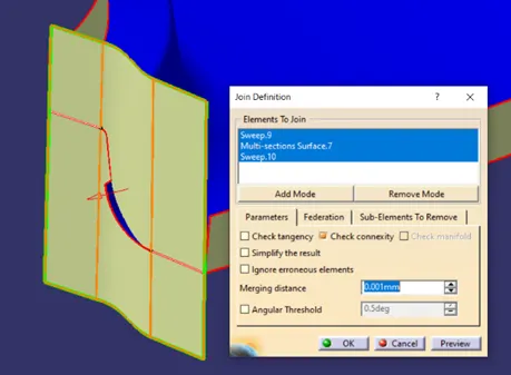
Use Multi Section Surface to create the missing patch and join them together to get Flange 1 surface.
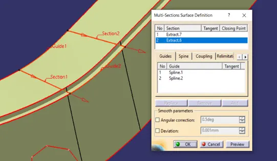
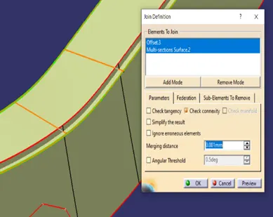
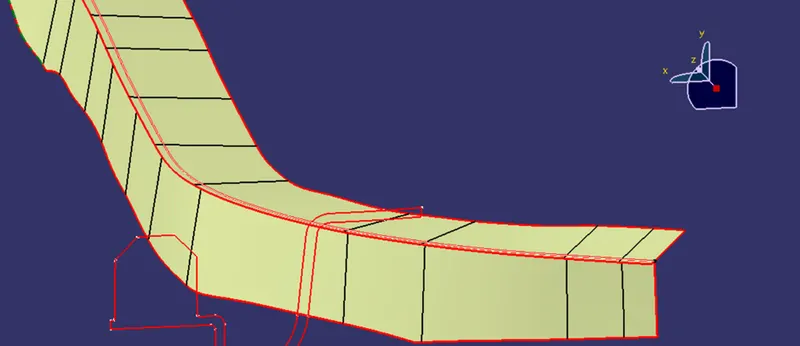
Flange 1 is created matching the Master Section Profile.
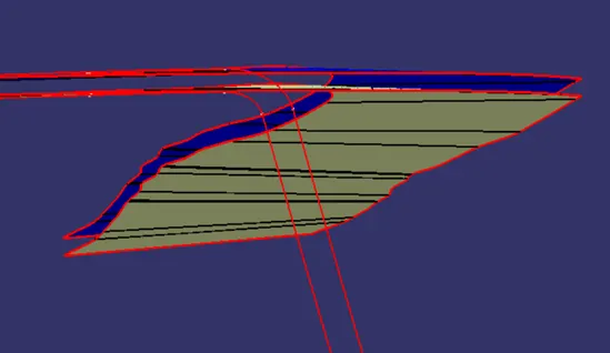
Similarly, Flange 2 is also created.
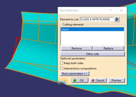
Trim both Flange 1 and Flange 2 surfaces along with given CLASS A surface to get Correct CLASS A which follows the given Master Section profile. Apply appropriate fillets to output surface. Final corrected CLASS A is shown in blue colour.
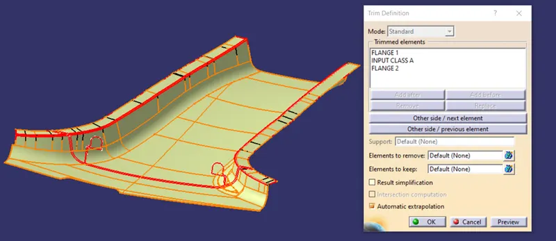
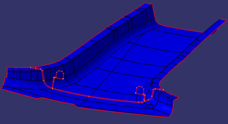
Before we proceed further, make small corrections on CLASS A surface patches to facilitate final trim operation.
Generating CLASS B Surface from CLASS A Surface as Input:
We are given a CLASS A surface as an input. Firstly, we have to generate CLASS B surface from given surface to generate solid component. CLASS B is generated by offsetting CLASS A surface. The critical parameter to consider is the component thickness. CLASS B is surface offset equal to part thickness.
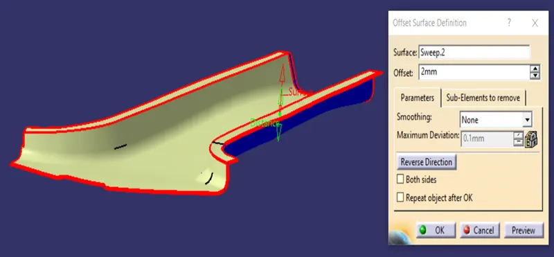
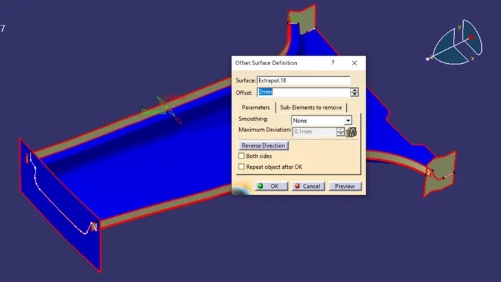
For generating CLASS B surface, offset given CLASS A, flange 1 and Flange 2 with offset value equal to 2 mm. Part thickness value according to Master Section is 2 mm. So, the offset value of 2 mm.
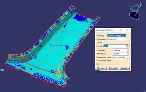
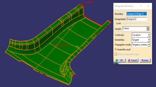
To facilitate trimming operation, CLASS A surface edge is extracted and extrapolated with small value.
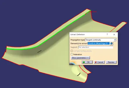
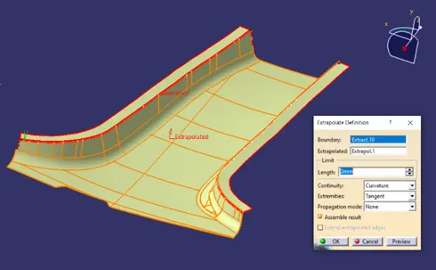
Trim Flange 1 and Flange 2 offset, with respect to CLASS A offset surface. Apply appropriate fillet values to get Final CLASS B surface.
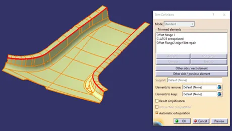
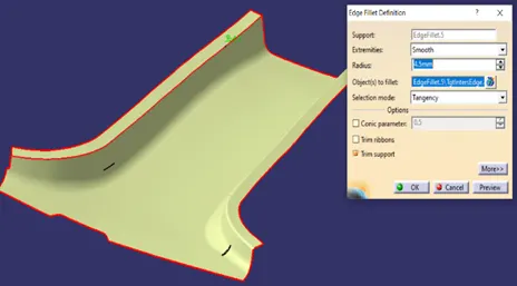
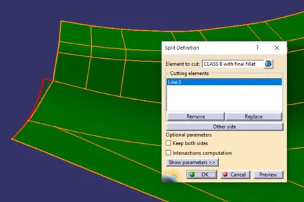
Before we proceed further, make small corrections on CLASS B surface patches to facilitate final trim operation.
Generating CLASS C surface from CLASS A surface:
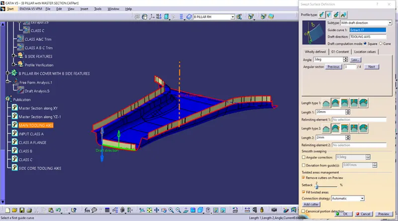
CLASS A surface is used as reference to generate CLASS C surface. We need to extract outer boundary from CLASS A surface. Extract boundary using “Multiple Extract” Command. Here we can use tangent continuity option to select appropriate edges. We have to use this command several times to extract all edges.
These surfaces are extracted, and sweep along the tooling axis with draft angle of 3°.
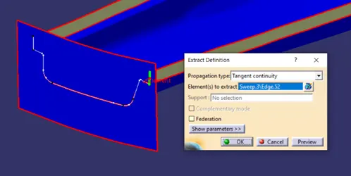
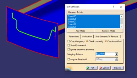
Some of the complex profiles need to be extracted and sweep separately. First, extract edges as shown below. Joint them together to get one single profile.
Extrapolate surface edges which are not intersecting with the adjacent sweep profile.
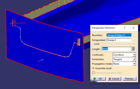
Some of the complex profiles are treated separately. One such profile is processed with edges extract, sweep them with respect to tooling axis. Use Multi Section Surface command to bridge the gap between them. Finally, Join them together.
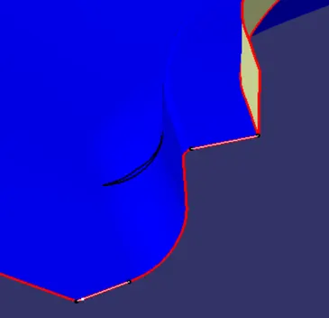
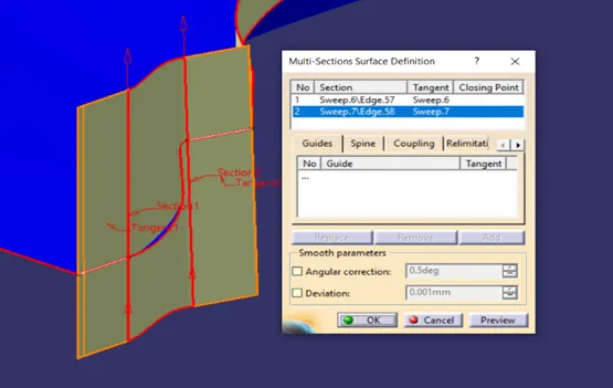
Repeat same operations for another side complex profile.
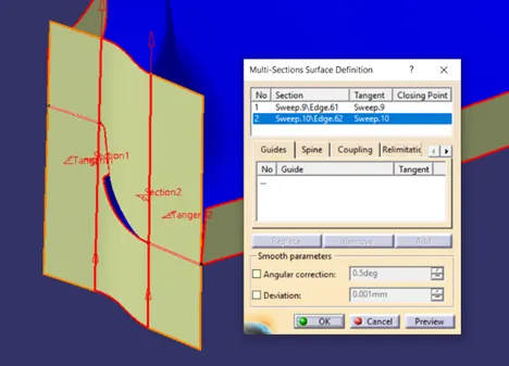
Two side profile sweeps which are aligned along with tooling axis direction and which are responsible for easy manufacturing of the component, we have to offset them so that it can be trimmed with CLASS A and CLASS B respectively.
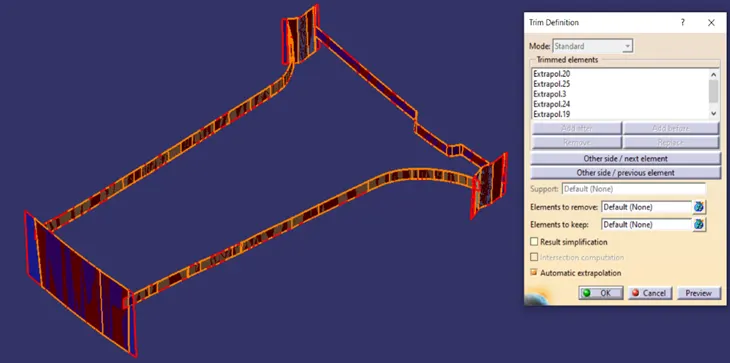
Now we have each profile separately sweep along tooling direction, trim them together to get final CLASS C surface.
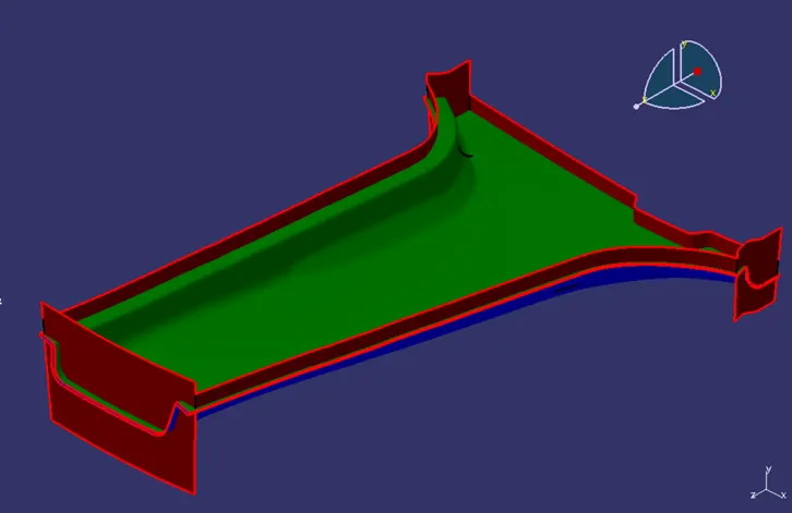
Overall, now we have CLASS A, CLASS B and CLASS C ready to trim with respect to each other to get closed surface part.
Trimming CLASS A and CLASS C:
Trim CLASS A and CLASS C surfaces together. Output is shown below.
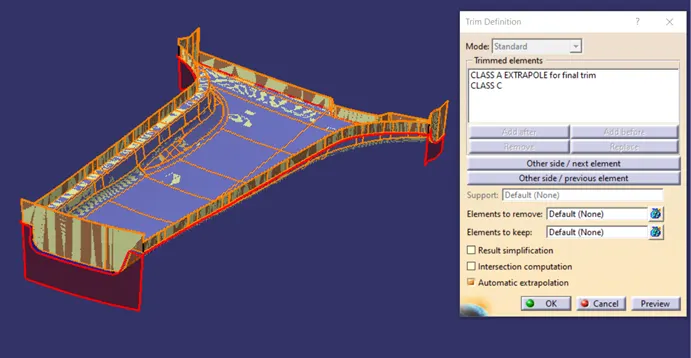
Generating Final Trim CLASS A, CLASS B and CLASS C:
Trim above output with respect to CLASS B surface to get surface component.
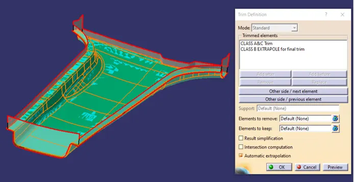
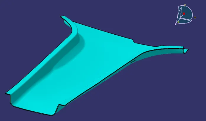
Final Output of the surface component is shown below.
Generating final plastic component from Surface component:
Above method has given a closed surface component as output. But, for manufacturing purpose, we need to have a solid body part. For that we need to migrate to CATIA V5 part workbench.
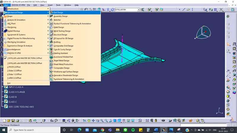
Here, in part workbench, we need to insert new body, insert menu “Body” command. This creates a new body inside part module.
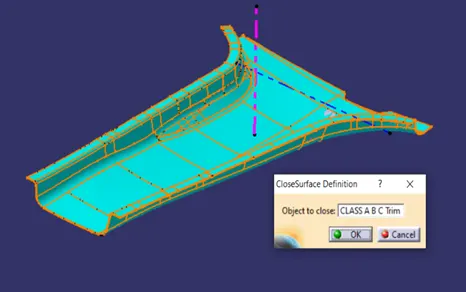
In body, we can use “Close Surface” command to convert our closed surface component to Solid body part. As the name suggests, all surfaces should be closed to get proper solid body.
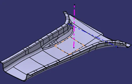
Choose the command and select our surface component. It will be converted to Solid body component. One of the main points is that, it won’t convert surface part to solid body if any of the boundary is open from surface component. And the final output solid part will be as shown in image.
Generating B Side Features:
B side features are Fixation features which are helpful while joining to plastic components together. B side features are named as they are always formed on CLASS B surface side of the part, which is not much of visual importance but serves basis for locating fixation features.
B side features can be Locators, Dog-house, Heat stakes or simple Ribs. Following the master section profile, we can distinguish the B side features such as a dog-house with locating pin over it and ribs spread across the component.
Dog-house:
Plastic Component B Side Feature - Dog House Analogy:
While designing Ribs or screw boss, sometimes the counter part is at some distance up to which Ribs or screw boss cannot be designed because of the defect limitations or failure chances. In those cases where mating parts are at certain distance, Dog House serve the purpose of providing height to the Rib or screw boss.
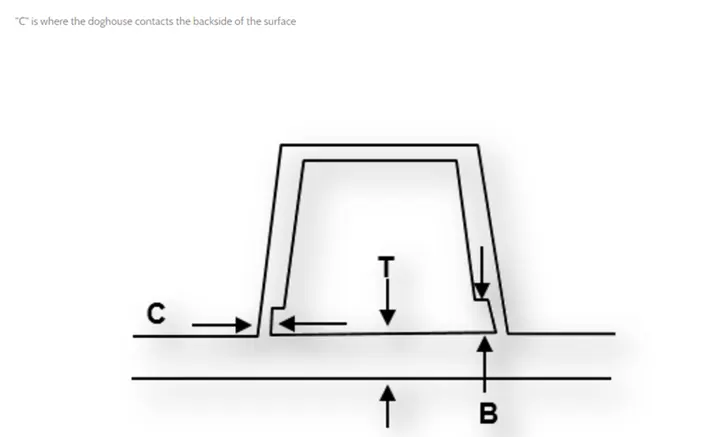
In general, Dog House is a shape having certain height from Base wall where we can mount screw bosses over the Dog house to solve the mating purpose. Here, dog house is connected to base wall. So, we have to consider the wall thickness at Dog house and Base wall portion. For Solving that purpose and to avoid sink marks to opposite surface, Dog house is designed in such a way that it’s wall thickness must be within standard rule dimension. More information we can derive from below thumb rules.
Dog House Design Parameters:
- Dog house dimensions can be taken as per requirement of length or height.
- Wall thickness at the base of the Dog house ‘C’ should be 40% or less than wall thickness.
- Height of ‘B’ should be between 3.0 to 6.0 mm
Dog House Design Thumb rules:
Creating a Dog-house following the Master section Profile:
Create point and make a plane with reference to master section profile and draw a sketch on that plane for dog-house profile. Take references from master section profile. Extract the edges that define outer profile of the dog-house.
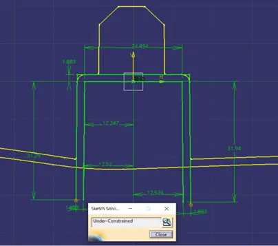
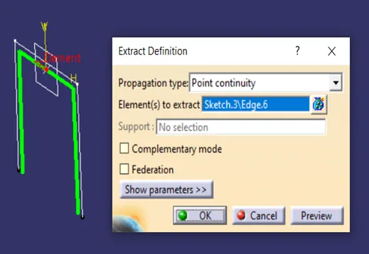
Extrude the profile using surface command.
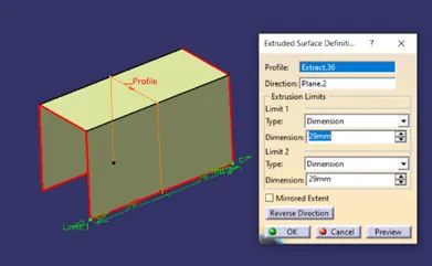
Similarly, create another plane with reference to another master section profile. Sketch the remaining profile with reference to another master section and extract the edges which are required to extrude.
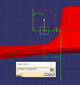
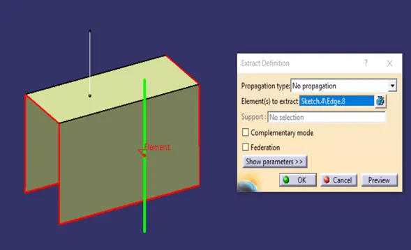
Extrude these two profiles and extrapolate them well to trim them with respect to dog-house outer profile.
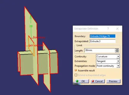
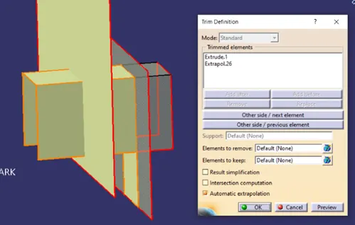
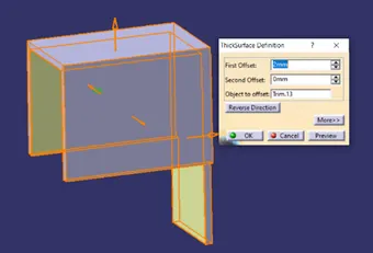
Convert output surface to solid feature by using thick surface command. Use another extruded surface to split the feature from front side. Provide draft to inner surface of the dog-house.
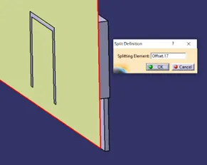
Dog-house is connected with base surface part such as its profile at base creates minimum wall thickness to avoid manufacturing defects. For that we create the avoid sink mark profile. To start with, extract the CLASS A base surface which is at base of the dog-house. Offset the surface by certain value as per dog-house design rules. Generally, 3.0 ~ 6.0 mm.
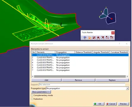
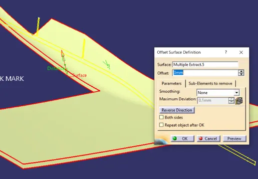
We have to make sure that inner profile of the sink mark feature, is properly designed to interact with shape of Main plastic component. Here, the component at base is complex in profile. We use intersect command to get the intersection between back surface of the dog-house and base offset surface. Once we get intersection, we prepare a sketch for inner profile of sink mark feature.
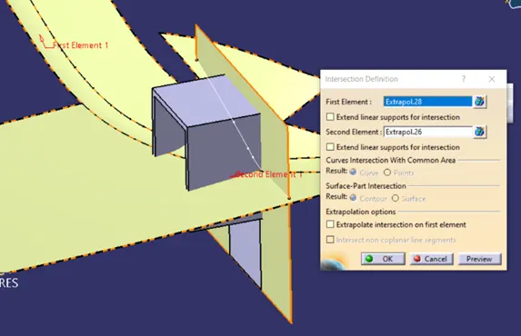
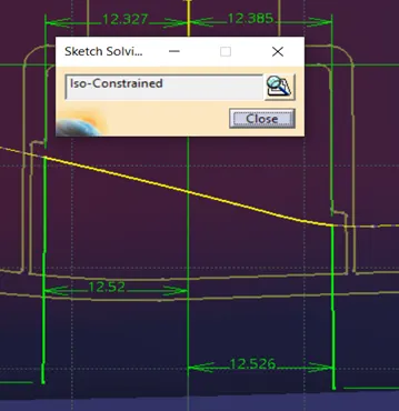
Extrude the inner profile and offset it by certain value. This offset should create the lower profile of the dog-house which at base, would result in minimum wall thickness.
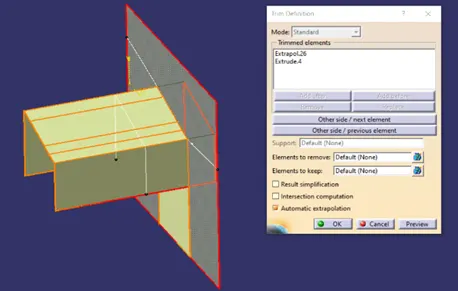
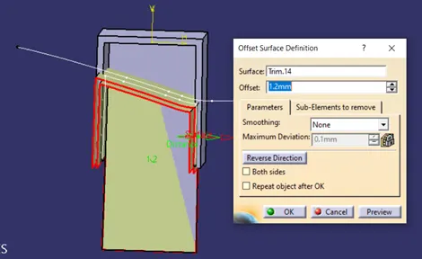
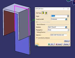
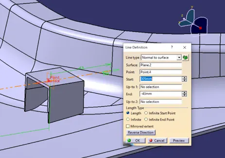
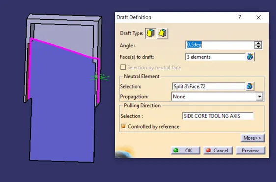
Split the dog-house feature by sink mark offset surface to create lower profile of the dog-house. Draft the inner faces of the lower profile of dog-house with respect to side core tooling axis. Create Side core axis or Lifter axis. It is simply created by using a point and a plane as reference.
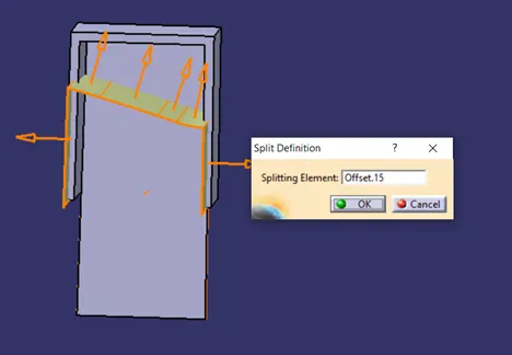
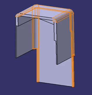
Draft the inner faces of the sink mark feature and apply appropriate fillets to inside and outside of the dog-house.
4 WAY Locator on top of Dog-house:
Our next fixation feature is Locator. It is similar to rib which is designed such way that it arrests the component location using push pin type features. Locator is designed by following Rib design rules for plastic component design.
Plastic Component B Side Feature – Rib Design Analogy:
Rib provides a means to economical stiffness and strength in moulded parts increasing overall wall thickness.
Ribs Facilitate,
- Locating and arresting components of an assembly with mating parts
- Providing Alignment with counter parts and other assembly components.
- Acts as a stop or guide for mechanisms.
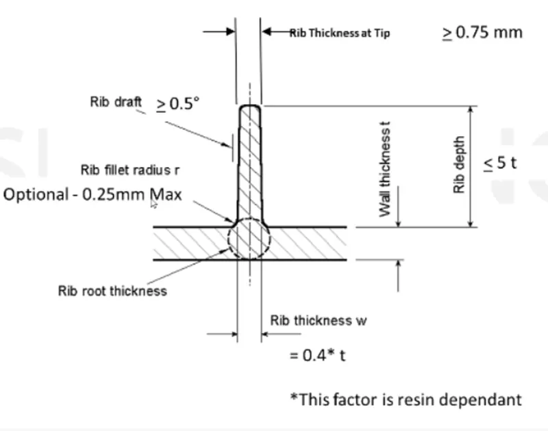
Rib Design parameters:
- Rib Thickness: Improper rib thickness generally cause Sink mark issues.
- Height: Generally Taller ribs provide greater support. Optimum rib height should avoid buckling.
- Rib Location: Two ribs should be at appropriate distance. Ribs on opposite walls should be offset.
- Quantity of Ribs
- Manufacturability of ribs
Rib Design Thumb Rules:
Creating 4 WAY Locator on given Component:
Here we have dog-house top surface. We use it as a reference to create the sketch for 4way Locator. First, we create point and a plane for our sketch.
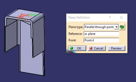
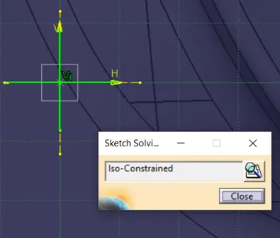
Use this plane to create the Sketch for 4 WAY Locator. Pad the sketch with certain value. Give appropriate draft to all faces of the Locator.
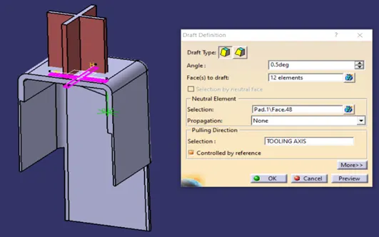
Here, we will be giving chamfer to the locator on top side to provide easy snapping to counterpart. Apply fillets to edges.
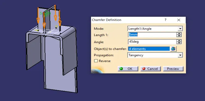
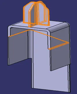
Trim Dog-house feature with respect to 4 WAY Locator. And again, trim them with respect to Main component.
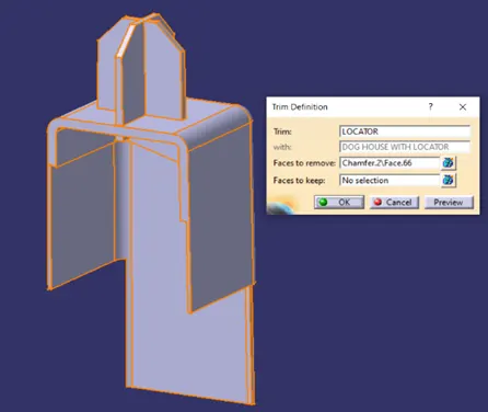
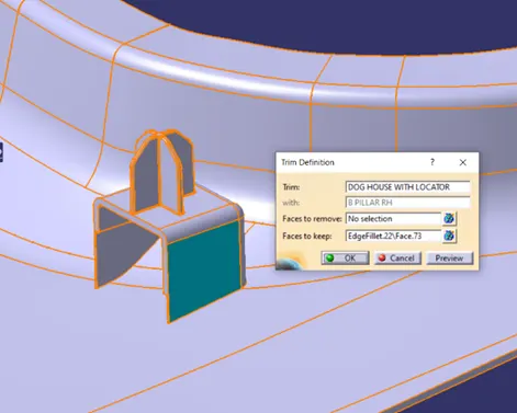
The same feature of dog-house along with 4 WAY Locator on top of it, is symmetrically present on the other side of the component. Make a symmetry plane and symmetry the same feature with respect to plane.
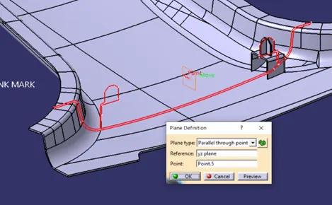
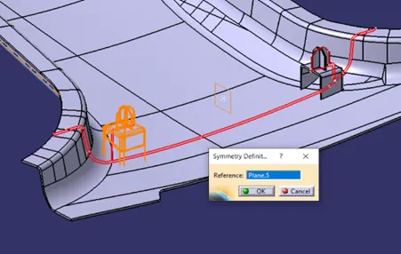
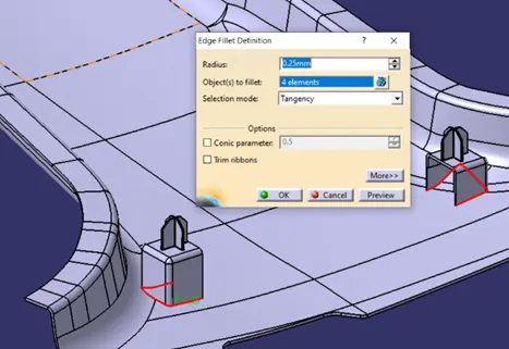
Apply base fillet of 0.25 mm value to the connecting base.
Rib Design across the component:
Following the same rules for rib design in plastic manufacturing, we can create ribs across the component.
Creating Ribs on given component:
Ribs will be positioned at different places across the boundary of the component. Make a rib profile sketch on the plane similar to locator sketch plane. Use a single line to define rib profile. Extrude the sketch.
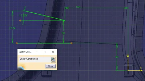
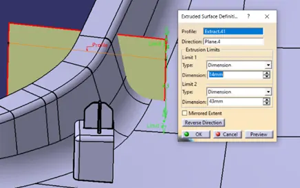
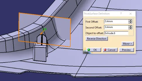
Use thick surface command to convert surface in to Rib feature. Extract the CLASS B surface and offset it so as to trim the Rib profile.
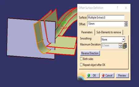
Use offset surface to split Rib profile. Draft The Rib feature faces with respect to side core axis and keeping CLASS B surface as neutral plane.
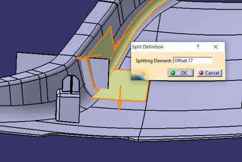
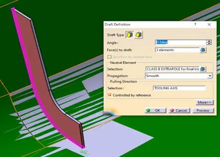
We have One Rib feature ready. We need to copy and translate Rib feature across the side portion of the component. Extract the edge and make different points on the curve to locate Ribs.
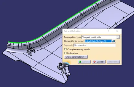
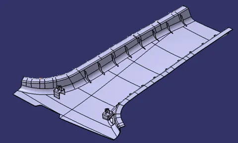
Copy and translate Rib feature at defined points. Trim them with respect to main component.
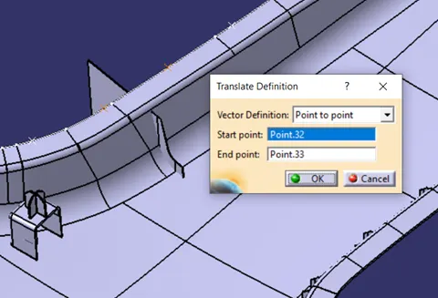
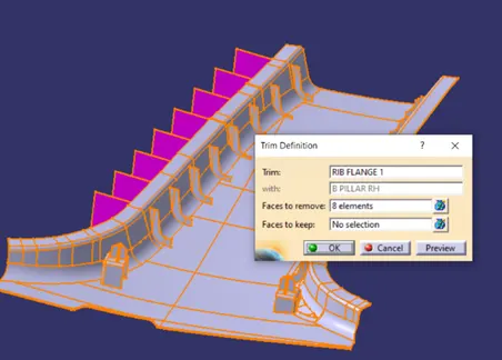
Similarly, Create ribs for another portion of the component. Trim them with respect to component.
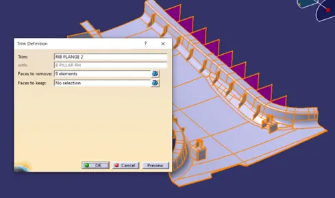
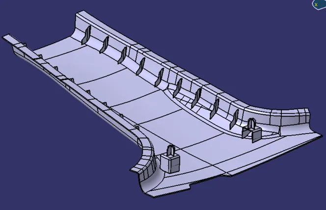
We can finally get the desired output. Final Component has Fixation features Dog-house with Locator and Ribs. All these features are following the master section profile.
Generating draft analysis on component:
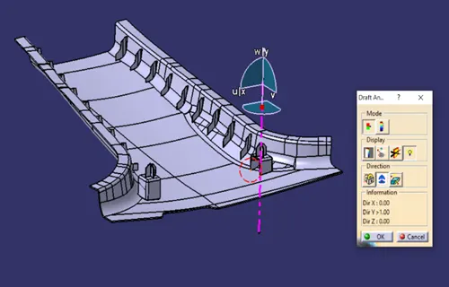
Draft analysis gives you the overall information about draft angles required with reference to main tooling axis of the component. While designing, we could give the draft angles to desired faces to clear the tooling direction. To evaluate given draft angles, we use draft analysis tool in CATIA V5.
Draft analysis steps.
- Material mode plays a vital role in generating draft analysis. The tool calculates draft angles required based upon material properties and behaviour during tooling operation. Not setting up, will give you a warning message.
- After setting material mode, click on “Feature Draft analysis” from Insert menu. A dialogue box will be opened.
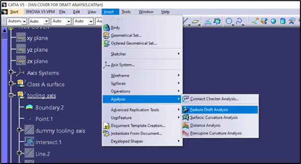
3. Use the compass option from the box, to align the current axis system with main tooling direction. It would create draft analysis with reference to tooling axis. Carefully align the axis system with main tooling axis and click on the component anywhere to create draft analysis.
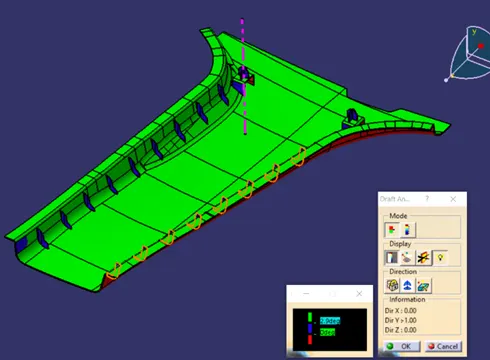
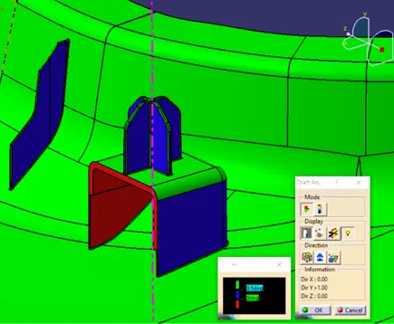
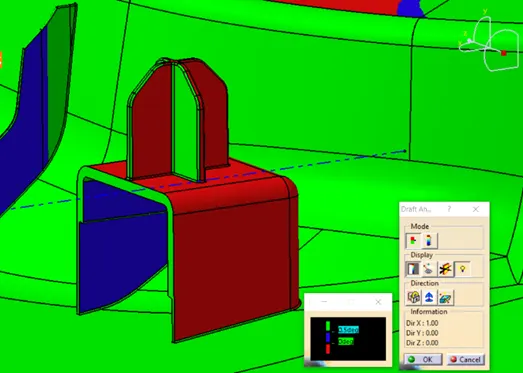
4. Locators and Ribs are also analysed with reference to main tooling axis. While as Dog-house inner faces are analysed with reference to Side core tooling axis.
Conclusion:
- Following Master Section profile, created main tooling axis and corrected CLASS A surface.
- Created CLASS B and CLASS C surfaces out of given CLASS A as input.
- Generated Solid body component from closed surface part.
- Created B side features such as 4 WAY Locator, Dog-house and Ribs. Designed total fixation strategy for assembly of two plastic components.
- Used the main tooling axis and Side core axis for creating draft analysis on the component.
Hence, we have successfully created CLASS B and CLASS C surfaces using given CLASS A, resulting in closed surface part. This surface part is converted to solid plastic component. Used main tooling direction and learnt about importance of draft angle and tooling axis for plastic manufacturing process.
Learned about Master Section profile, B side fixation features and created features on the main component. Used draft analysis to check the feasibility for manufacturing.
References: