MBD Simulation on IC Engine Valve Train
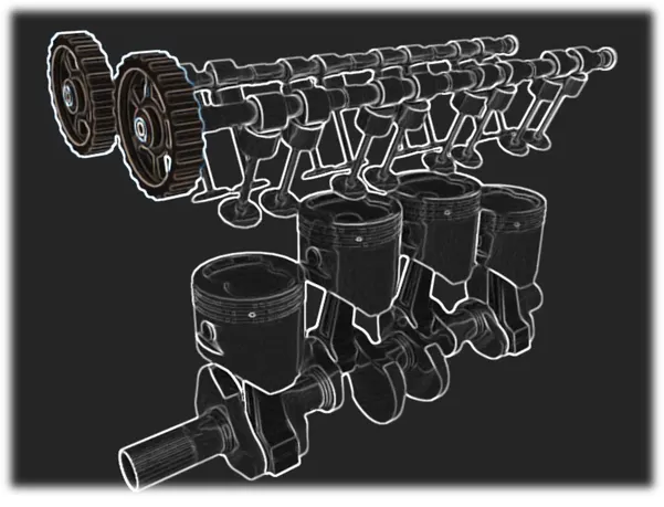
AIM: MBD Motion analysis for IC Engine Valve train.
OBJECTIVE: Simulating IC Engine valve train for different cam lifts and comparing results.
Key Points:
- Brief of IC Engine valve train and application
- Design of Cam, Pushrod, Rocker arm and Valve
- Initial setup for motion study and Calculation
- Plotting different parameters and Comparison
- Conclusion
- References
IC Engine Valve Train:
Valve Train is a mechanism that controls intake of Air/fuel mixture into engine and also exhaust gases from the same. Inlet and exhaust valve lift are controlled by cam profile. Major components are described below.
Cam: A cam is a carefully designed profile which is responsible for controlling valve lifts. Cams are mounted on camshaft. Profile of a cam is designed to control valve timing diagram for engine inlet and exhaust valves.
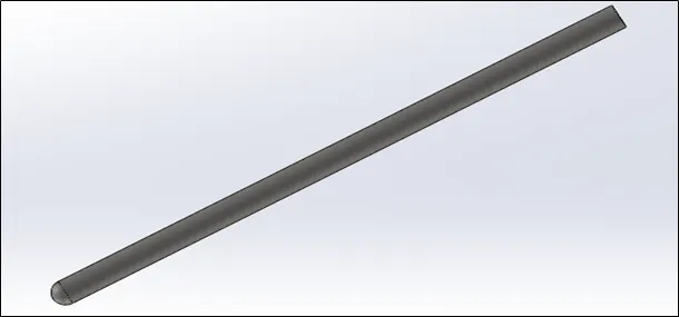
Pushrod: Pushrod is a cylindrical rod which connects cam to rocker arm. It acts as a major link between cam and valve mechanism. Plays critical role in transmitting motion with proper timing for inlet and exhaust.
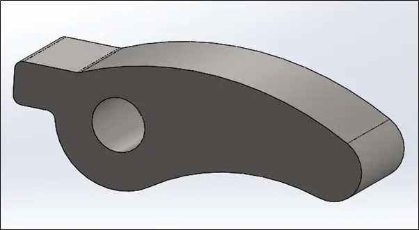
Rocker arm: Rocker arm acts as a pivot between pushrod and valve base. Overhead camshaft engines may not have rocker arm but overhead valve engines use rocker arm, which are actuated by a pushrod and pivot on a shaft in order to actuate valves.
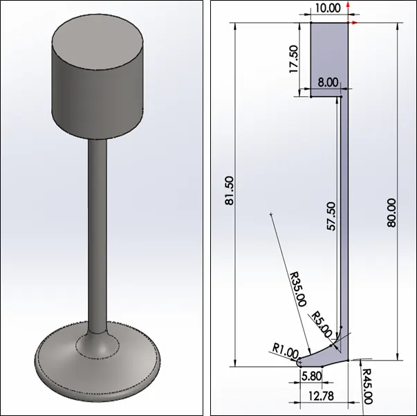
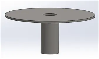
Valve and valve base: Valve creates an opening gateway for letting Air/fuel mixture intake as well as exhaust. Valve base controls motion of valve and also provides base for spring which is responsible to actuate valve.
Application:
As the name itself suggests, Valve trains are Used in IC engines to control air/fuel and exhaust gases. This combination finds its application in many areas of automotive industry mainly inside Engine blocks. Most prime movers use piston-crank assembly as primary mechanism to convert energy into mechanical motion.
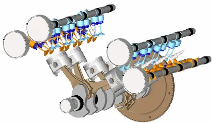
Design of IC Engine valve train:
Design of Cam:
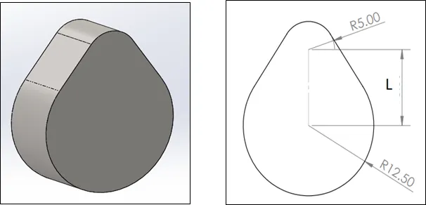
Design of Cam profile is a critical parameter with reference to valve train diagram. Cam profile consist of a lobe shape on profile which controls valve lifts.
Cam lift formula:
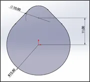
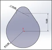
Cam Lift: (L-R1) +R2 (Equation 1.)
L = Centre distance between two centres (Valve lift)
R1 = Diameter of lower circle (R12.50 mm)
R2 = Diameter of upper circle (R5.00 mm)
Design of pushrod:
Design of rocker arm:
Design of Valve:
Design of Valve seat:
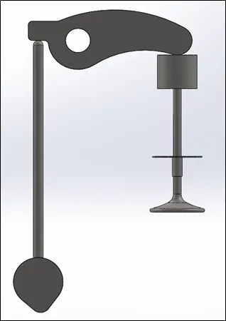
IC Engine valve train Assembly:
Main assembly depends upon the relative motion between all the parts. Constrain cam first because it works as input parameter in our study. Next, we can constrain pushrod, rocker arm, valve seat and valve as shown in image below.
Use Move command and apply physical dynamics option to check relative motions. The correct position of cam will give accurate motion during study.
Initial setup for motion study and Calculation:
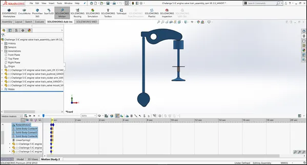
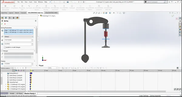
After the assembly is completed, we can setup the motion study. Given motor input to cam. Establish Solid body contact between cam and pushrod, pushrod and rocker arm, rocker arm and valve respectively. Use 7200 fps and “Precise contact” Option to achieve high accuracy for each degree rotation of cam. Apply spring effect between valve base and valve seat with Spring stiffness 10 N/mm and free length 45 mm. Material applied for each component is same i.e. Cast Carbon Steel.
Calculating Valve lift (L):
Following inputs are given
|
No. |
Cam lift |
Cam Speed rpm |
Material |
|
Case 1 |
3.5 mm |
1500 |
Cast Carbon Steel |
|
Case 2 |
6 mm |
1500 |
Cast Carbon Steel |
Valve lift for Case 1: - Valve lift for case 2: -
Cam lift = (L-R1) +R2 Cam lift = (L-R1) +R2
3.5 = (L- 12.50) + (5.00) 6 = (L- 12.50) + (5.00)
L = (3.5+12.50-5) = 11 mm L = (6+12.50-5) = 13.5 mm
Setting up Motion Study:
Solid body contact
Spring: Stiffness = 10 N/mm , Free length = 45mm
FPS:
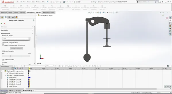
After setting up the assembly, set timeline to 0.2 sec just to have shorter calculation time. Start calculation and may take a while to calculate. Finally, results are calculated and compared.
Plotting results and comparison:
Case 1: Cam lift 3.5 mm
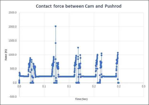
1. Contact force between Cam and Pushrod
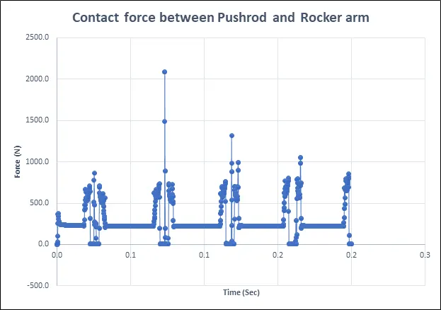
2. Contact force between Pushrod and Rocker arm
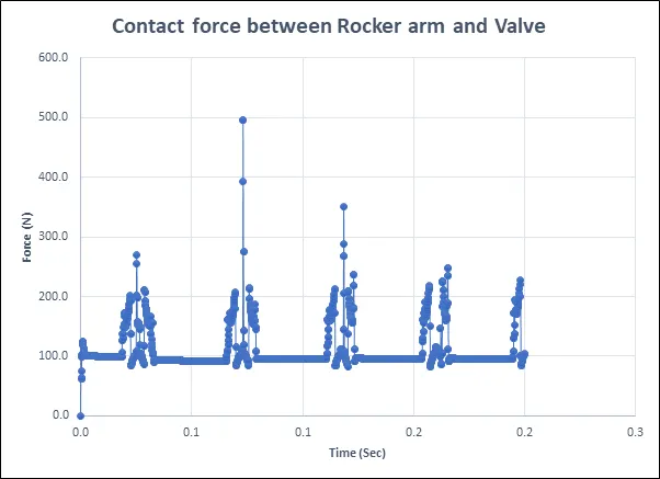
3. Contact force between rocker arm and Valve
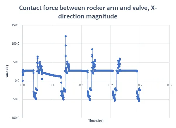
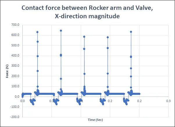
4. Contact force between rocker arm and valve, X-direction magnitude
Case 2: Cam Lift 6 mm
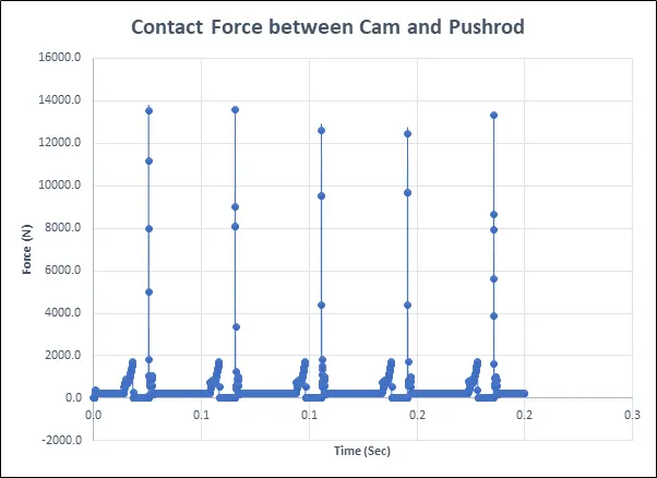
1. Contact force between Cam and Push rod
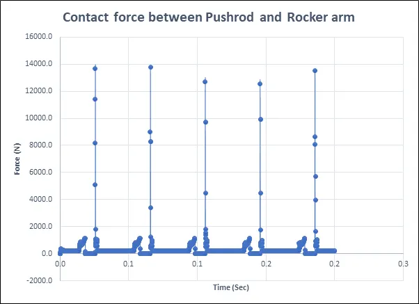
2. Contact force between Pushrod and Rocker arm
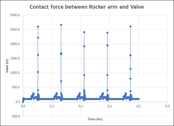
3. Contact force between Rocker arm and Valve
4. Contact force between Rocker arm and Valve, X-direction magnitude
Conclusion:
- In our two cases, the contact forces between two bodies generated due to friction between them. Also contact force is highest when cam lift is completed and pushrod comes down. All the parts follow same phenomena.
- Contact force between rocker arm and valve is checked in two ways, direct magnitude and the value of force as X-direction component. X-direction component represents friction between valve and rocker arm. The positive and negative values represent direction of friction force weather towards origin and away from origin alternatively.
- Comparing both cases for cam lift, only the magnitude is changed. While as reaction remains same. Also increasing cam lift, will also increase the ratio of Air/fuel mixture intake through valve.
Animation:
MBD IC Engine Valve Train:
Case:1 Cam lift is 3.5 mm
Case:2 Cam lift is 6 mm
References: