Base Bracket Plastic component Design through the given Class-A surface.
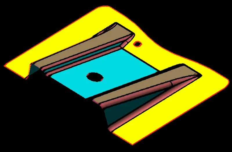
AIM: Create the Base Bracket Plastic component Design through the given CLASS A surface. .
OBJECTIVE: Generating Plastic component for Base bracket from given CLASS A surface. Brief about CLASS B and C surface and use it to prepare solid plastic component.
Key Points:
- Bisecting method for generating Main Tooling axis
- What is CLASS A, CLASS B and CLASS C surface?
- Generating CLASS B surface from given CLASS A
- Generating CLASS C surface from given CLASS A
- Joining CLASS A and CLASS C
- Generating Closed surface using CLASS B trim
- Generating final plastic component from Surface component
- Generating draft analysis on component
- Conclusion
Tooling Axis (Bisecting Method):
Tooling Axis is an imaginary axis in which direction the tooling operation is performed. In Injection molding, the direction in which the mold is opened / closed, is called tooling direction.
The draft angle, which also plays a major role in plastic component design, is decided with reference to the main tooling axis of the component.
Bisecting method for generating Main Tooling axis of component.
1. The given Input will be CLASS-A Surface of the component, which we need to verify for boundary discontinuities.
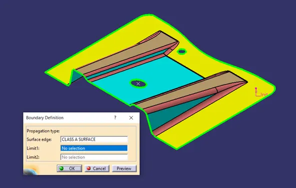
2. Then we can make a dummy tooling axis for reference by approximating from part geometry. Observing component from different directions, we can assume the dummy tooling axis location.
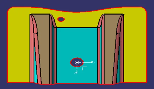
That would also help as first step of bisecting method. Assuming Tooling Axis in Y direction, it is clear that the hole in the component will not be cleared by Y direction tooling axis.
Similarly, if we assume, tooling axis in X direction, the hole as well as the side wall drafts are not easy to clear by X direction tooling axis.
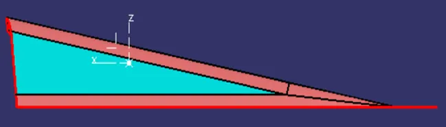
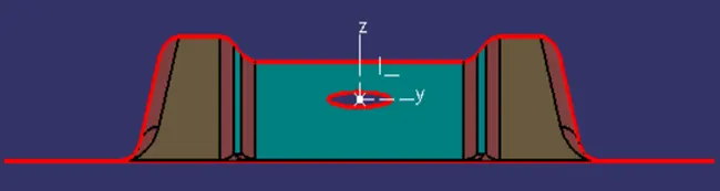
Now the Z direction tooling axis, clears the hole on top as well as the drafts on sidewalls of the component. It is evident from below image that Z direction should be the Tooling axis of the given component.
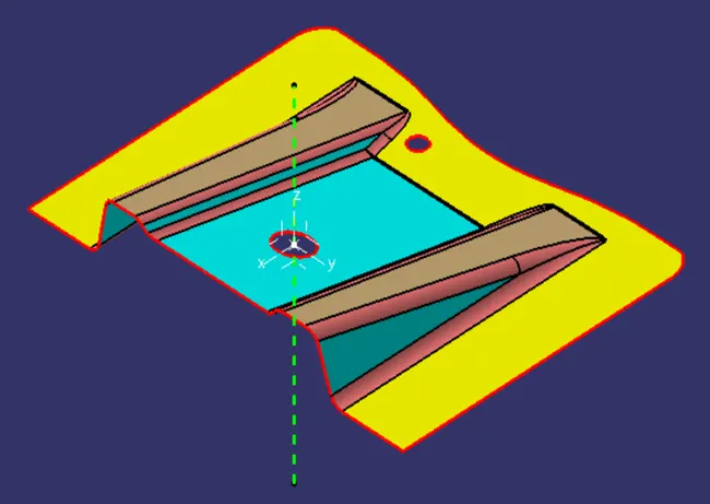
3. Now that the tooling direction is defined, we can make temporary tooling axis for the part as shown below. Taking the hole profile as a reference, below image shows temporary tooling axis in Z direction.
Taking it as a reference, we can proceed to define actual tooling axis using bisecting method.
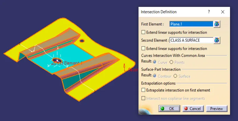
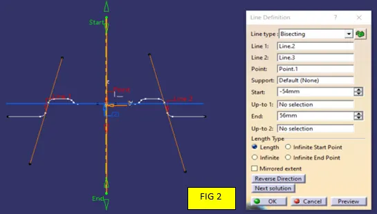
4. Bisecting method will use reference lines created from different intersections of component with reference planes. Firstly, take intersection of component with XZ plane to get profile as a reference.
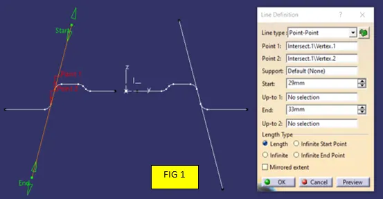
Create two lines parallel to profile as shown in FIG 1. After creating two parallel lines, create a bisecting line from those two lines FIG 2.
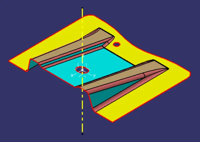
5. The last bisecting line would be the main tooling axis for the given component. Yellow one shows the main tooling axis of the component. Depending upon complexity of components,
it is possible that we get tooling axis out of the component area. It is not necessary to get tooling axis on the component.
What is CLASS A, CLASS B and CLASS C surface?
CLASS A: In automotive design, CLASS A surface refers to any set of free form surfaces with high quality finish. These surfaces have curvature and tangential alignment to ideal aesthetical reflections and surface finish. In simple words, CLASS A are the outer most surface of the component which are directly visible to, and in touch with end consumer. CLASS A plays major role in aesthetic quality and visual appearance of the product.
Automotive applications such as Exteriors (Body bumper, door panel, grill, Lights) and Interiors (Dashboard, Door interior trims, Seating). Other product design applications include Industrial housings, Injection molded components, home appliances, toys etc.
CLASS B: These are the surfaces we see sometimes, are secondary surfaces, but are less important. These surfaces also must be smooth and free from any errors, but are held below CLASS A quality as these surfaces will not affect aesthetic appearance of the part. It usually have ribs, boss, snap etc.
Inside surface of components (Coin holder, arm rest, Door interior trims, Body bumper, door panel, and grill) which are not visible directly or may come on touch with end user, are called CLASS B.
CLASS C: These are the backside the surfaces of the component which comes in contact with other assembling parts/components. These surfaces can have tooling marks, abnormality or flashes. These surfaces are equally important for fit and assembly purposes. These are not majorly important from aesthetic perspective.
Generating CLASS B Surface from given CLASS A:
We are given a CLASS A surface as an input. Firstly, we have to generate CLASS B surface from given surface to generate solid component. CLASS B is generated by offsetting CLASS A surface. The critical parameter to consider is the component thickness. CLASS B is surface offset equal to part thickness.
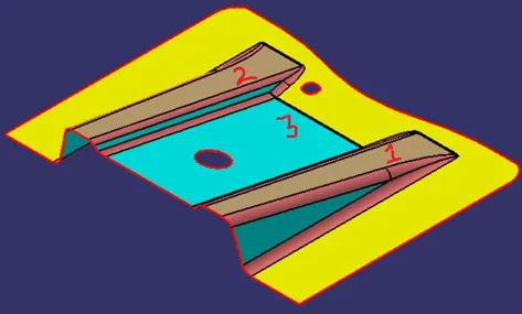
Given CLASS A is divided into three main surfaces which will be helpful in generating CLASS B surface. Below image shows the CLASS A, and methodology to follow in next steps.
Offsetting First Rib:
Avoiding fillets given here, first rib can be divided into 3 surfaces. Each surface is extracted from CLASS A, Untrimmed and extrapolated to get the desired output. It will form the base for final CLASS B surface.
Extracting the surface highlighted in green, using “Extract” command.
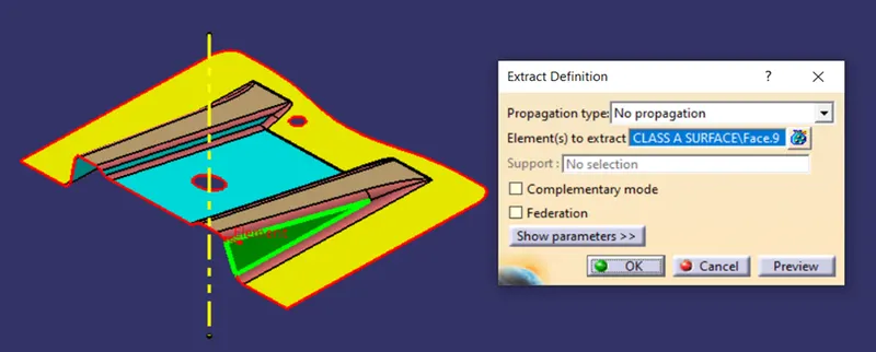
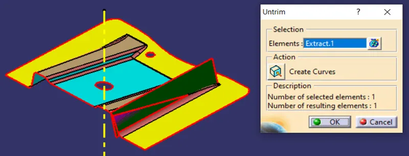
After extracting the surface, Untrimmed it using “Untrim” command. The green surface is untrimmed to some extent. Shown in Dark green colour.
To further extend the surface, we can use “Extrapolate” command. It will extend the surface tangentially in all the directions. It will be useful in final trim of the component.
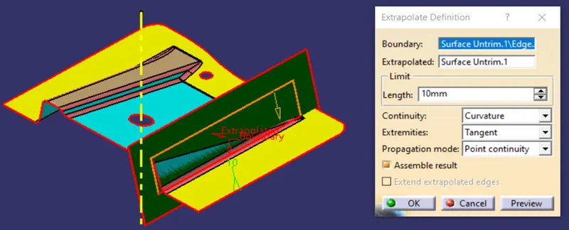
This is how, the first surface is extracted from CLASS A to form base of CLASS B surface.
Further continue the same process to Extract, Untrimmed, Extrapolate the surfaces to from base for rib 1 CLASS B surface.
Surfaces in Pink are extracted from CLASS A input. These surfaces, after Untrimmed, Extrapolated, shown below in FIG 3.
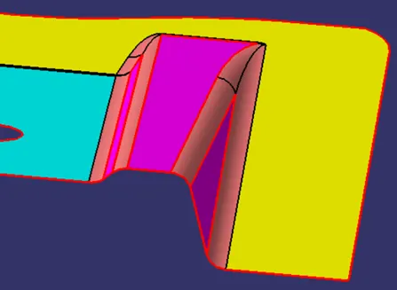
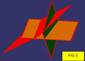
These, Extrapolated surfaces are need to be trimmed to achieve desired output as CLASS A surface. Using “Trim “command, we can achieve the output as shown below.
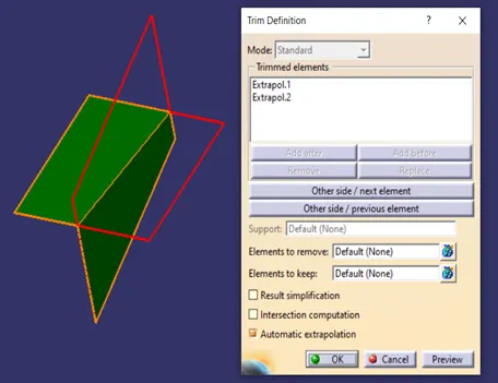
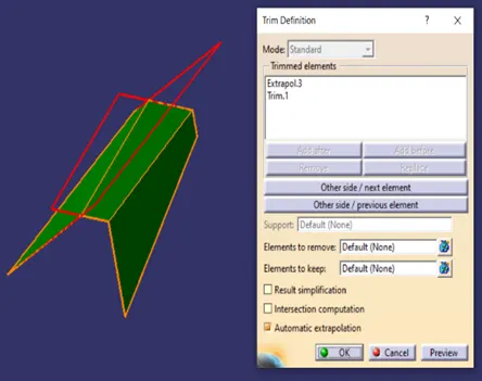
After trimming, Final Output is shown as below, green surfaces. This creates the base for rib 1 CLASS B surfaces.
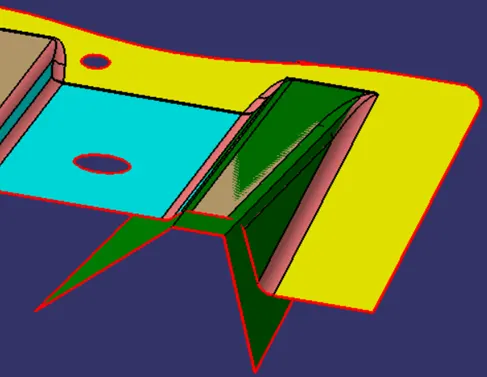
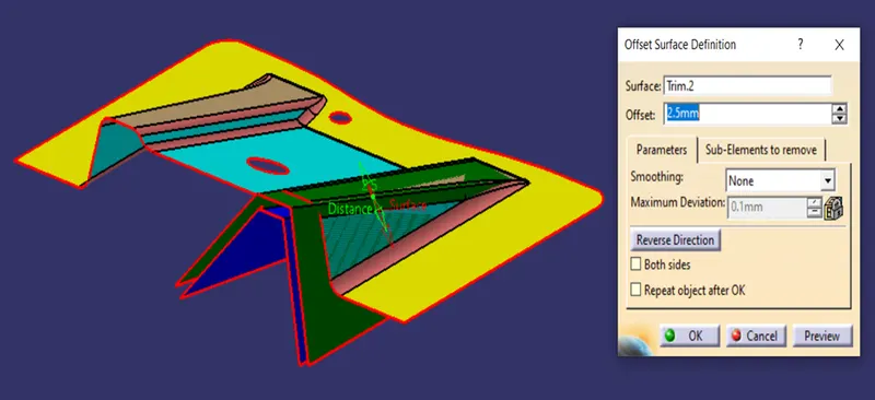
This surface need to offset from CLASS-A surface, by the value equal to part thickness. Here the part thickness is 2.5 mm. So offset value is set to 2.5 mm. Surface in the blue colour is the Final Output of Rib 1 CLASS B surface.
Similarly, we can generate, extract, untrimmed, and extrapolated and offset surfaces for Rib 2. Below image, surfaces shown in red are final output for Rib 2 CLASS B surface. Along with it, surface with hole is also extracted, untrimmed, extrapolated and offset which is shown in Pink colour.
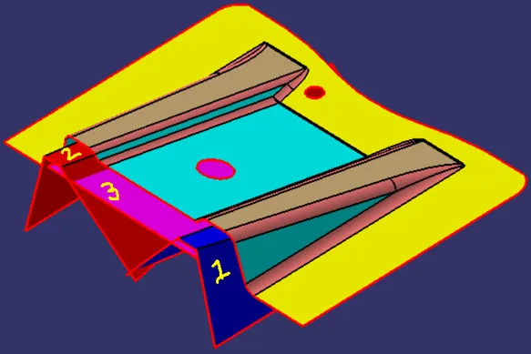
As in above image, Surface 1, Surface 2, Surface 3 need to be trimmed to get desired final CLASS B. Firstly, Trimming Surface 2 and Surface 3 as shown below.
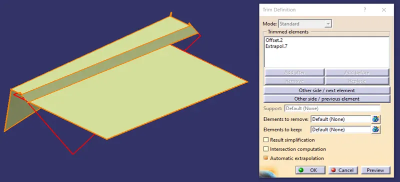
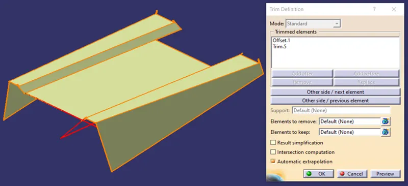
Above output surface need to trim with Surface 1, will get desired offset surface as output.
Our next task is to extract base surface from CLASS A and offset it to get base for CLASS B. Extract the base surface highlighted in green. Untrimmed and extrapolated the surface.
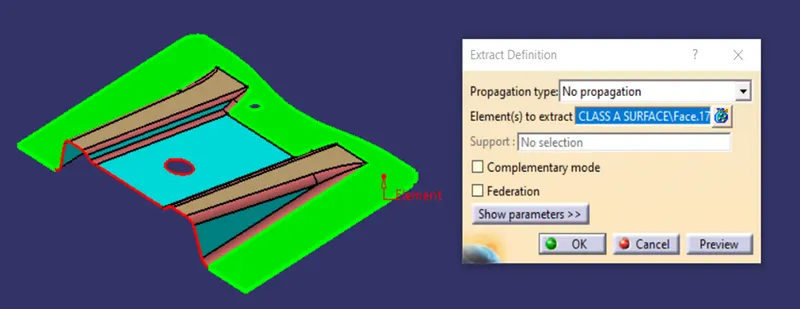
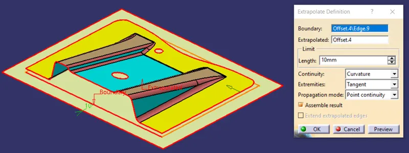
Now, we can trim the base surface with previously created output surface. It will result in CLASS B surface.
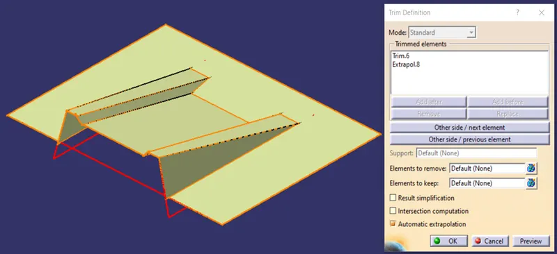
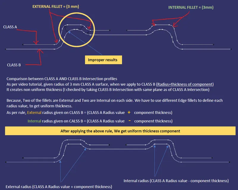
Generating fillets on CLASS B is easy task. But the critical parameter is value of radius to be given.
CLASS B surface is offset from CLASS A, by value equal to part thickness. So there can be two possible types of radius on CLASS B. One is internal radius and the other is External radius with reference to CLASS A surface. Both concept are equally important to design part with uniform wall thickness throughout the component. Detailed explanation can be derived from following slide.
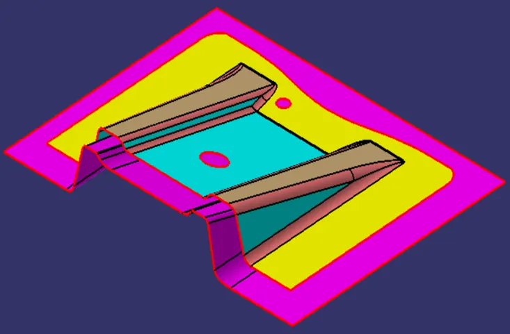
Final CLASS B after giving fillets as per above method, is shown in pink coloured surface below. We can clearly identify the difference between CLASS A and CLASS B.
Generating CLASS C surface from given CLASS A:
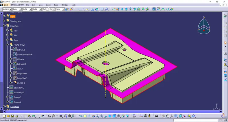
CLASS A surface is used as reference to generate CLASS C surface. We need to extract outer boundary from CLASS A surface. Extract boundary using “Boundary” Command.
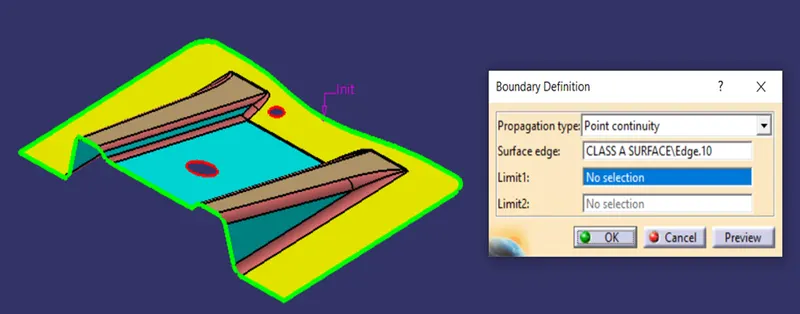
Extracted boundary is used to generate CLASS C surface using “Sweep” command. This surface is sweep along tooling axis to generate draft angle along tooling direction. We need to be careful while generating draft angle wrt tooling axis.
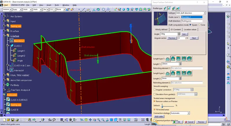
Sweep command has option called, “with draft direction”. The blue arrows show the drafting direction. Generating improper draft angle can result in wrong draft analysis. Orange arrow will indicate the selected drafting direction.
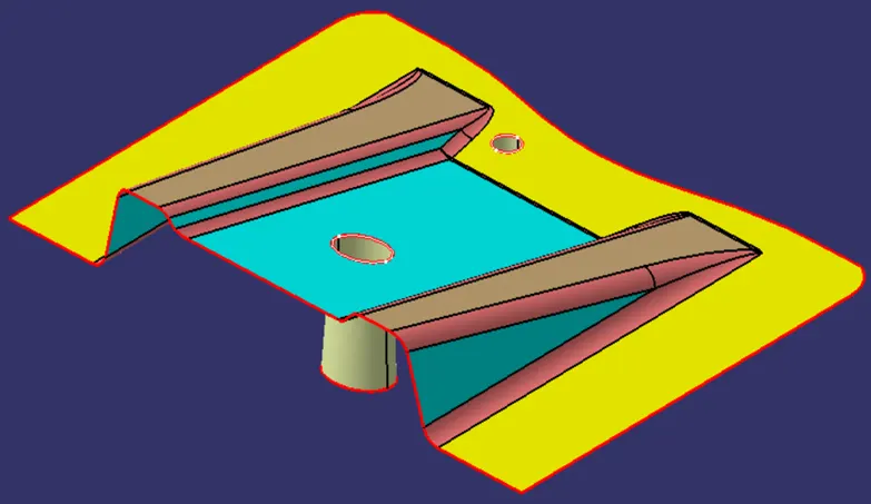
Here, we are generating outward draft wrt tooling axis so that whole component can be cleared in tooling direction. Required draft angle is 3°. Surface in brown represent Final CLASS C surface.
Similarly we can sweep two circular profiles for holes in tooling axis direction, together we can join with other surfaces.
Joining CLASS A and CLASS C surfaces:
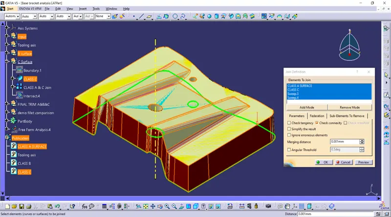
IN above methods, we have generated CLASS B and CLASS C surfaces using given CLASS A surface of the component. Now to create a closed surface part, we need to trim these three surfaces accordingly.
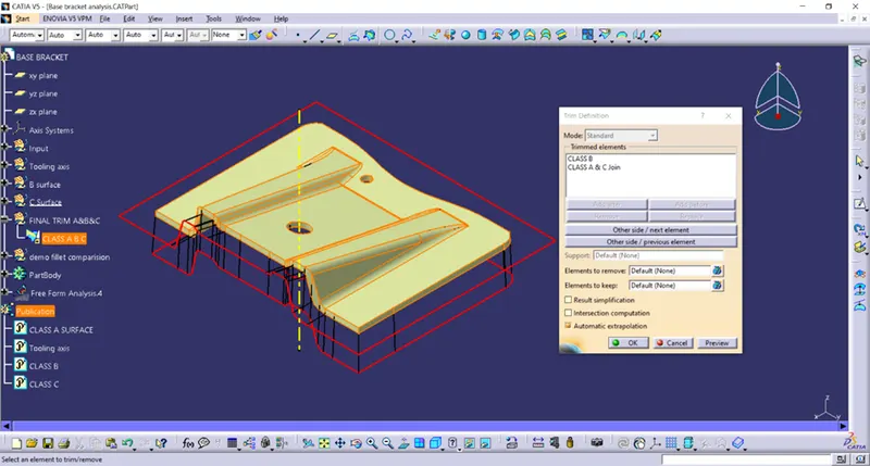
First we will be joining, CLASS A and CLASS C surfaces. We can use “trim” command.
Generating Closed surface component from CLASS B trim:
Following output we get after joining CALSS A and CLASS C. Now we aim to trim the output surface with CLASS B (pink surface) to get final output as surface part.
Generating final plastic component from Surface component:
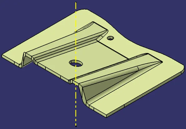
Above method has given a closed surface component as output. But, for manufacturing purpose, we need to have a solid body part. For that we need to migrate to CATIA V5 part workbench.
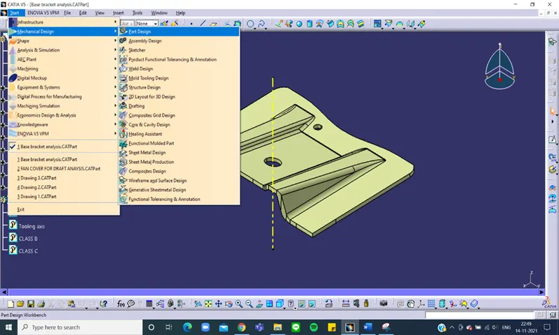
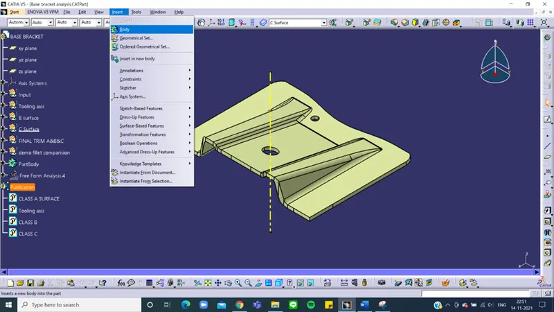
Here, In part workbench, we need to insert new body, insert menu “Body” command. This creates a new body inside part module.
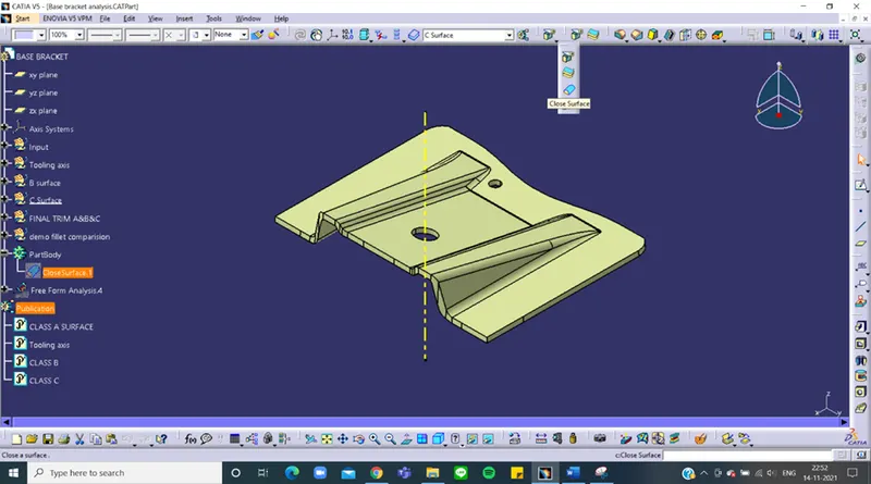
In body, we can use “Close Surface” command to convert our closed surface component to Solid body part. As the name suggests, all surfaces should be closed to get proper solid body.
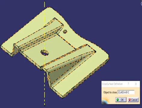
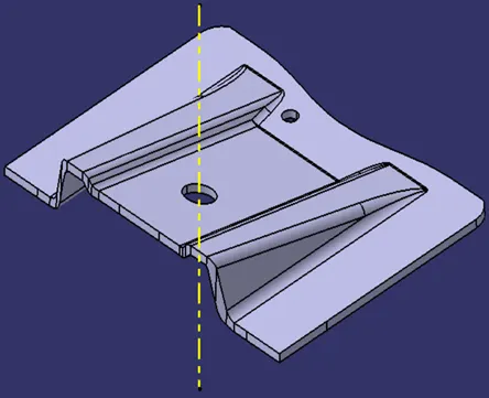
Choose the command and select our surface component. It will be converted to Solid body component. One of the main point is that, it won’t convert surface part to solid body if any of the boundary is open from surface component. And the final output solid part will be as shown in image.
Generating draft analysis on component:
Draft analysis gives you the overall information about draft angles required with reference to main tooling axis of the component. While designing, we could give the draft angles to desired faces to clear the tooling direction. To evaluate given draft angles, we use draft analysis tool in CATIA V5.
Draft analysis on final solid part.
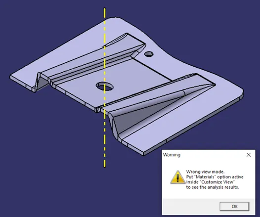
- Material mode plays a vital role in generating draft analysis. The tool calculates draft angles required based upon material properties and behaviour during tooling operation. Not setting up, will give you a warning message. We can select “Material” mode from given options.
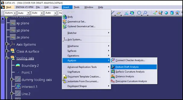
2. After setting material mode, click on “Feature Draft analysis” from Insert menu. A dialogue box will be opened.
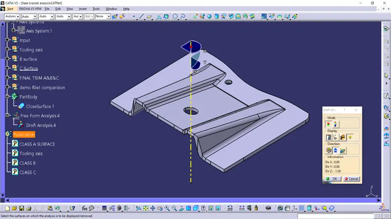
3. Use the compass option from the box, to align the current axis system with main tooling direction. It would create draft analysis with reference to tooling axis.
Carefully align the axis system with main tooling axis and click on the component anywhere to create draft analysis.
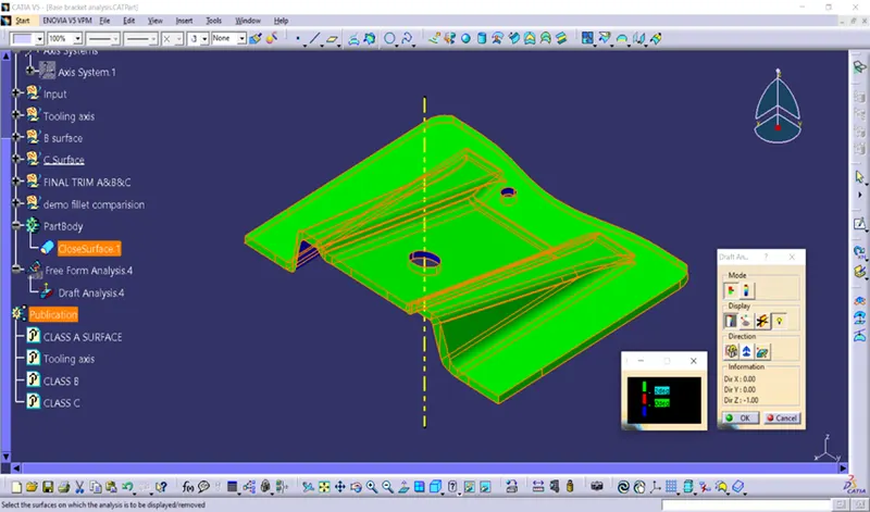
The colour legend has several colour codes. They describe value of draft angle. Out part draft angle is given as 3°. Green colour shows surfaces having draft angle more than 3°.
Red coloured surfaces shows draft angle of 0°. And the blue colour shows surfaces with negative draft angle.
Conclusion:
- Created the Tooling axis using bisecting method.
- Created CLASS B and CALSS C surfaces from given CLASS A surface.
- Generated solid body component using closed surface feature.
- Used the main tooling axis for creating draft analysis on the component.
The conclusion here is, if we get any surfaces draft angle below defined value, it will be shown in red colour. As of now, all surfaces have appropriate draft angle. It shows our part will clear tooling axis direction without any difficulty.
References: