Analysis of a Buckling Formula for Cyclonic separator.
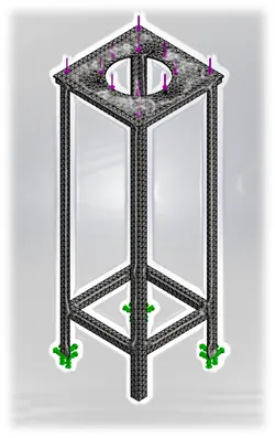
AIM: Buckling Analysis of a cyclone separator stand
Objective: Change in buckling stress and Factor of safety when using stiffener casing for the stands. Performing design study for optimum position for stiffener and optimum Factor of safety for given load under buckling phenomena.
Key points:
- What is buckling phenomena
- Geometry of separator stand
- Setting up simulation
- Result comparison
- Conclusion
- References
What is Buckling Phenomena:
- Buckling is sudden change in shape of a structural component or deformation of member under load. A structure subjected to gradually increasing load, a member may suddenly change shape when load reaches a critical level, then the structural member is said to have buckled.
- Buckling may occur even though the stresses developed in structure are well below the yield stress of component’s material. However, if buckling may not cause complete loss, the stress is distributed among other structure members when in large assembly.
Geometry of Cyclone separator stand:
- This geometry is given as CAD input. Initially we do not have any stiffener casing for stands. Initially we will be analyzing this geometry under certain loading condition for buckling and will also take out Factor of Safety.
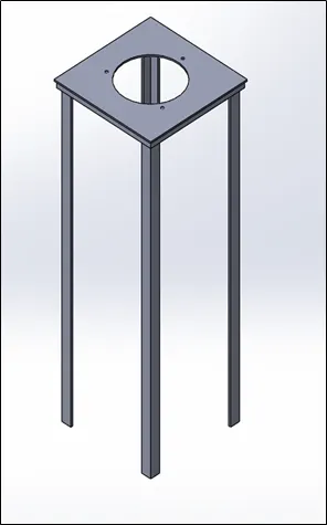
Setting up Simulation:
We aim to initially analyze the stand for buckling under certain load and note the results for buckling vibration amplitude. Also, we will be noting Factor of safety without adding stiffener casing.
Pre-processing:
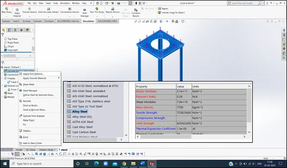
- Defining material. We have selected default material as alloy steel (same for each case) from Solidworks material library. Below image shows material properties. Need to consider here that Alloy Steel Maximum Yield strength is 620 N/mm2.
- Open Solidworks Simulation and opt for New study. Choose buckling analysis module.
Solving:
- Run the Buckling Analysis model from following screen.
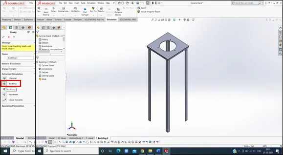
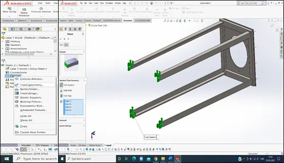
2. Next, we will apply boundary conditions. Fix four ends of stand so as to fix the base during analysis.
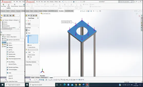
3. Here applied force is 150kN on top face of stand.
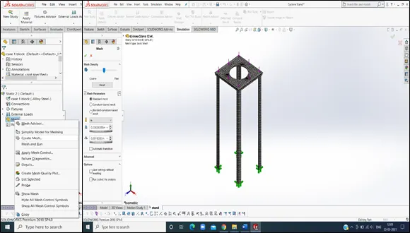
4. Next step is meshing. Meshing is also called as discretization which splits whole component into small elements. Each element is solved for defined boundary condition. Then data is interpolated for whole component.
Here defaults mesh of 6mm is used.
After finalizing boundary conditions, we can run the buckling analysis study. Here it will give values appropriate for Buckling Amplitude. Stand is subjected to vibration upon loading. Therefore, the output comes as vibration frequency amplitude. Also we can take out present value for Factor of safety upon which our component is survive.
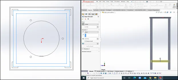
In another case, we will be performing buckling analysis while providing a stiffener casing for stands. The geometry for stiffener case design is very simple. Below Image shows 3D meshed model of cyclone sand separator stand with stiffener casing.
|
Stiffener casing covering boundaries of stand as seen in sketch image. Extruded up to 75 mm, starting 175 mm away from top surface of stand. |
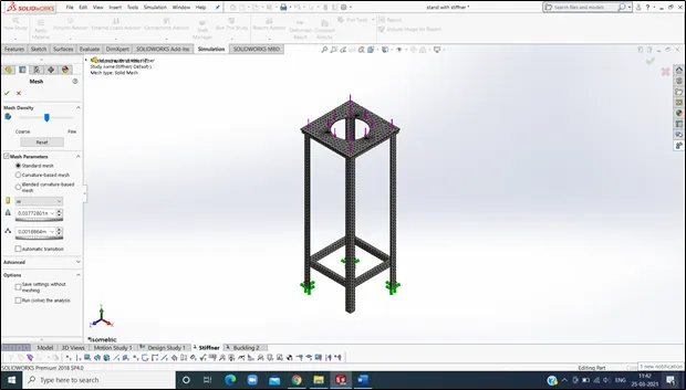
Similar to previous case, buckling analysis is performed for the stand with stiffener. Results are compared for both cases.
Post processing:
Post processing will consist of data which we required as output of simulation study. For the buckling analysis, we get buckling amplitude values for component under given load. It may show some deflection under stress. Here it is also important to observe the change in factor of safety for two different cases.
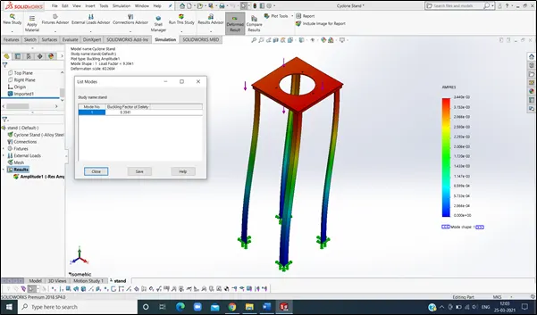
Case 1: Stand buckling analysis without stiffener.
Observation:
Buckling Factor of Safety: 9.40
Amplitude: 3.4 X 10⁻³ m
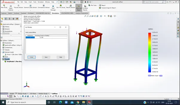
Case 2: Stand Buckling Analysis with stiffener casing.
Observation:
Buckling Factor of Safety: 12.30
Amplitude: 3.2 X 10⁻³ m
Case 3: Performing Design Study for Optimum position of stiffener casing. Also optimizing Buckling Factor of Safety for given material and given load condition.
Geometry is same as in previous case. Design study allows user to check different possibilities for which the analysis data is required. Here, we aim to optimize position of stiffener for optimum Factor of safety.
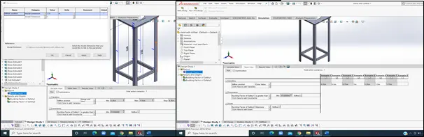
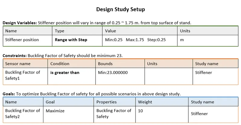
Summary of Design Study results obtained:
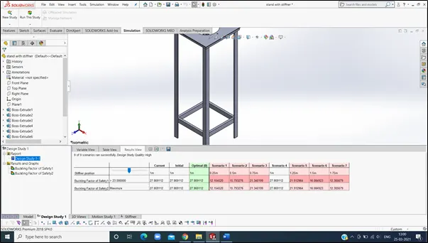
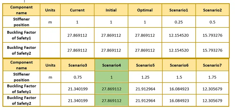
Summary of Results Obtained:
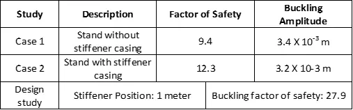
Conclusion:
- In both cases, when compared, we can observe that buckling effect is reduced when we add stiffener casing.
- Among two cases, there is negligible difference between obtained values of buckling amplitude. While in case 2, buckling tendency is less than case 1.
- Factor of Safety is increased significantly when stiffener is added.
- After performing design study, optimum distance for stiffener casing is 1 meter from top of stand. Also Factor of safety obtained in the case is 28 which is maximum among other cases.
References: