Motion Study of Internal Geneva Mechanism, Solidworks
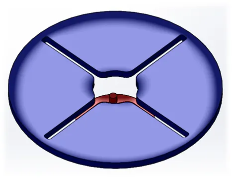
AIM: Motion Study of Internal Geneva Mechanism
OBJECTIVE: The report describes detailed simulation of Internal Geneva Mechanism with Motion study.
Key Points:
->What is Geneva Mechanism, Types and Application
->Design the Driver and Driven components
->Simulating Assembly using Motion Study
->Plotting different parameters and Comparison
->Conclusion
->References
What is Geneva Mechanism?

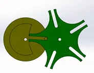
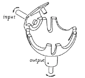
A) Internal Geneva B) External Geneva C) Sperical Geneva
Mechanism Mechanism Mechanism
A simple mechanism which controls the constant rotary motion to intermittent rotary motion is called Geneva Mechanism. It contains a driving part which is connected to a prime mover. Driving and driven components are connected in a way that pin of the driving part sets into slots on driven part. Geneva Mechanism has irregular gear teeth unlike the regular gear mechanisms.
The output rotary motion depends upon the number of slots on driven part and speed at which driving part rotates. Thereby continuous rotary motion is converted to intermittent motion.
Types:
- External Geneva Mechanism
- Internal Geneva Mechanism
- Spherical Geneva Mechanism
Application:
Most common type used is External one. Due to its sturdy operation and ability to withstand higher stress, it finds application in Tool changer turret with some of the CNC or VMC machines, modern film projectors etc.
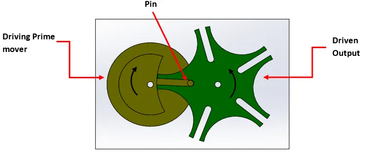
Design of Driving and Driving Components:
Here we are aiming to Create Internal Geneva Mechanism for the sake of simulation. Solidworks 2018 is used to model components with Solidworks motion installed from Add-ins.
Design of Driving Component:
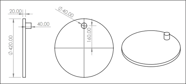
Design of Driven Component:
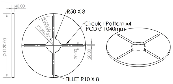
Following the above drawings, both parts are created and saved with respective name.
Note: Here one important thing is that we will be requiring distance between centre of both components. Which will be used during assembly to align components properly.
Assembly of the components:
In Solidworks Assembly environment, insert both components. The first part inserted, is fixed by default. Right click that part and click float. Now both parts are free to align inside assembly.
First, I have fixed driving part as it is connected to prime mover with fixed location. Align driver so as it can only rotate about self-vertical axis. Ensure that, the said rotating motion is only allowed to the driver. Use “Mate” command to apply appropriate mates between assembly planes and driver part.
After aligning driver, we can align driven component w.r.t driver. Insert mates so that driven component sets up on the top face of driving. Make sure, vertical centre axis of both the components are on the same plane. As shown below in the image.
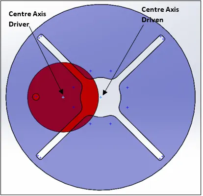
The important thing here is the distance between two centre-axis of both parts. I have traced out the path of pin and accordingly set the centre distance.
Ensure the driven component has only one motion allowed i.e.it can only rotate about its vertical centre-axis.
Assembly of components is completed.
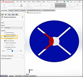
In assembly environment, use “Move” or “Rotate” command to check if the desired motion is achieved. Use “Physical Dynamics” option for real time simulation of motion.
Simulating Motion Study:
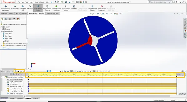
In the assembly environment, we find “Solidworks Motion” tab in a Solidworks Add-ins and a New motion study tab at bottom of the screen. Enable Solidworks Motion from Add-ins, go to the Motion Study tab and select motion study in the indicated window.
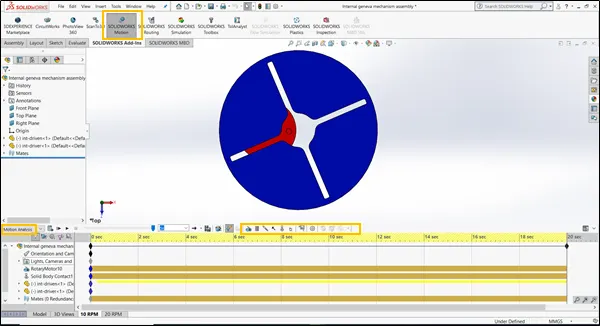
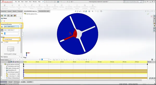
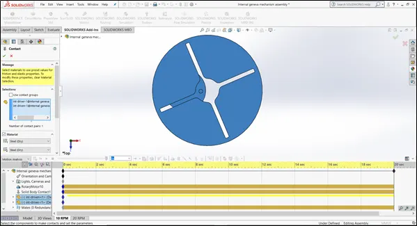
Motion analysis has different option for generating desired motion between relative parts. For example, we will be using “Motor” Option to give rotary motion to the driving wheel. And to establish a contact between driving and driven part, we will be using “Contact” Option. Both are explained below.
Motor:
It is used to simulate rotary motion of prime mover at driving part. Different options are available to simulate required motor motion. We will be using constant motor.
Contact:
Contact option establish the contact between solid bodies during simulation. Both bodies behave like in constant contact during simulation. We can also apply material, friction coefficient if required.
Setting up relative motion between two parts is completed here.
Simulation, processes the provided data with given input conditions and process it using solver. Solver is the one who performs calculations during study and gives required results. Solver does very complex calculations in the background during simulation. Simulation process always depends upon the complexity of the problem, capability of solver, system configuration etc.
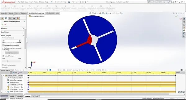
So, to get more accurate results, we have to set certain parameters such as frame rate and contact accuracy. Motion study property manager helps to set these custom parameters.
Running the motion study:
Set the initial timeframe for the simulation to run. Click on the “Calculate” button. Now, solver may calculate the study and give required output. Once the calculation is complete, we can animate the motion using buttons provided.
Plotting Results and comparison:
Motion study calculation data can be accessed using “Results and plot” option. This option provides us with various plotting parameters such as forces, displacements, velocity, momentum, energy, power etc. We will be plotting a few.
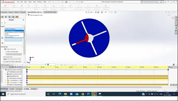
Plotting and comparison:
We are considering two predefined scenarios for the sake of comparing different parameters.
- When Motor is at 10 RPM (60 fps)
- When Motor is at 20 RPM (120 fps)
We will be plotting following parameters for both the scenarios.
- Contact force between driving and driven part as a function of time.
- Angular displacement of driven wheel.
- Comparison of contact forces with and without “Precise contact”
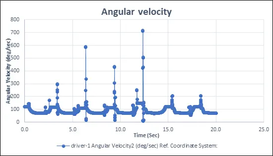
- Angular velocity of driver wheel
Motor: 10 rpm
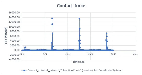
- Contact force between driving and driven part
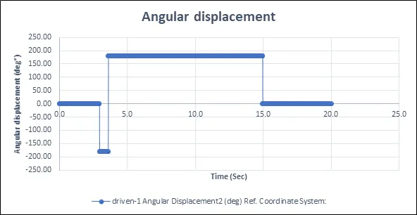
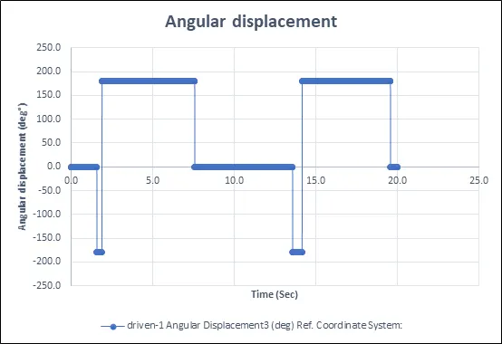
2. Angular displacement of driven wheel
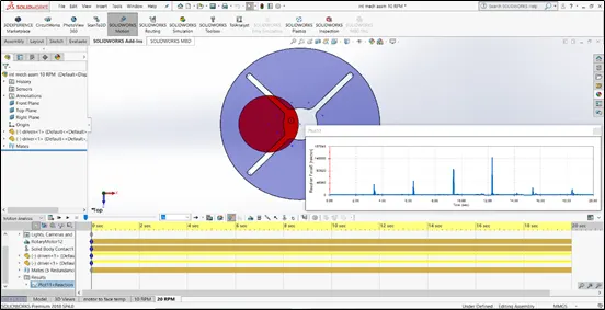
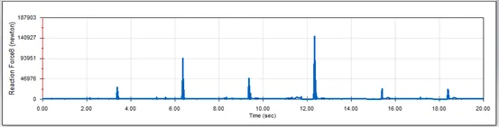
3.Contact forces between driver and driven, with & without using “Precise contact” function.
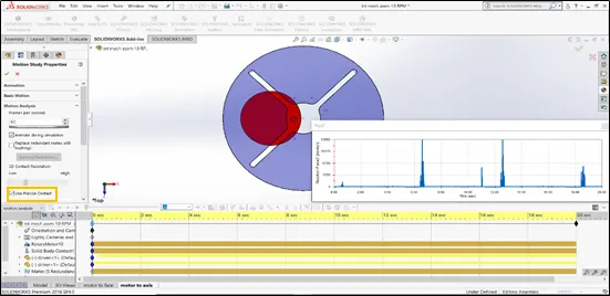
Use of Precise contact
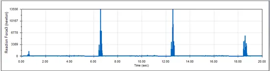
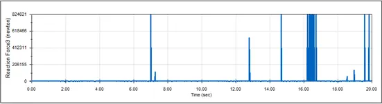
*Contact force precise contact enabled *Contact force precise contact disabled
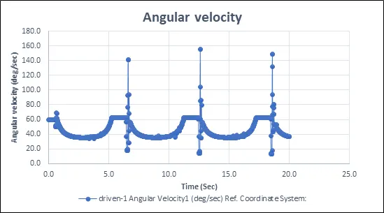
4.Angular velocity driver wheel.
Motor: 20 rpm
- Contact force between driver and driven
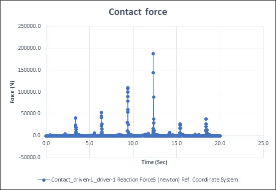
2.Angular displacement of Driven wheel
3.Contact forces between driver and driven, with & without using “Precise contact” function.
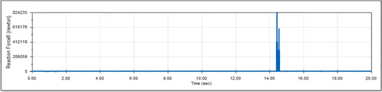
*Contact force precise contact enabled *Contact force precise contact disabled
4.Angular velocity driver wheel
Conclusion:
- Increase in Motor rpm, tends to increase contact force between both components.
- In both the cases, angular displacement is between -180° to +180°. So, we can conclude that angular displacement of driven wheel does not change with motor rpm.
- Angular velocity of driver wheel increases with increase in rpm. A universal statement is followed here.
- “Precise contact” feature is very useful. During simulation, it manages to have precise contact with two bodies. Failure to use that feature may cause the system to misbehave during simulation and results may be inaccurate.
While “Precise contact” is disabled, the contact force does not change with each count.
Hence Enabling option, we can get accurate contact force at each rotation and during every Jerk.
References:
Link for Internal Geneva Mechanism : Internal Geneva Mechanism