B Side Features Design _Center console Plastic component
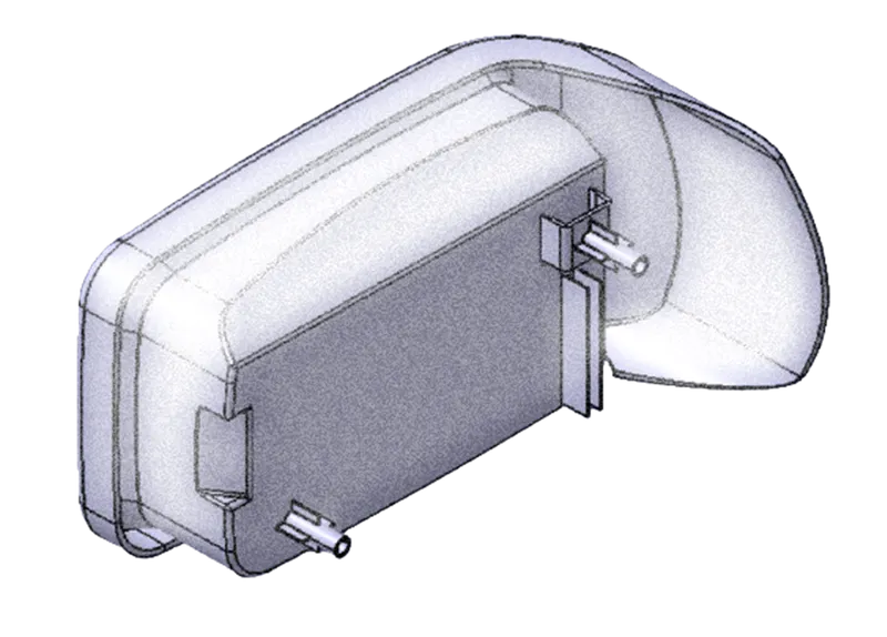
AIM: Creating B Side Feature – Screw Boss and Dog House Design Using CATIA V5.
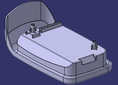
OBJECTIVE: Creating B Side Feature – Screw Boss and Dog House Design on Center console coin holder plastic component.
Key Points:
- What are the Plastic component defects and their types
- Plastic Component B side features Screw Boss design analogy
- Creating Screw Boss on given component
- Plastic Component B side features Dog House design analogy
- Creating Dog House on given component
- Screw Boss Design parameters verification with given standard values
- Dog House Design parameters verification with given standard values
- Generating draft analysis on component
- Conclusion
What are the Plastic Component Defects and their types:
Making Injection mold component involves lot of mathematical calculation. High level of technical expertise is required to prevent small mistakes. Preventing such a circumstance is all about highly competent design.
Basically, a defect which shows undesired surface or output which is directly affecting the end user experience, can be considered under plastic defect. Defects causes component to uneven surface finish, dis-functioning or even failure.
Basic types of Plastic defects which are considered in manufacturing process.
- Flow Lines
- Sink Marks
- Vacuum Voids
- Surface Delamination
- Weld Lines
- Short Shots
- Warping
- Burn Marks
- Flash
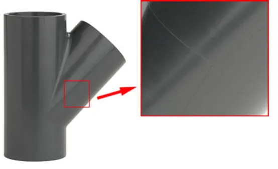
Flow Lines:
Flow Lines are streaks, patterns or lines- commonly off-toned in colour. Flow lines show up on the part as a consequence of the physical path and cooling profile of the molten material, as it flows into mold.
These defects are caused by the varying speed at which the molten plastic flows as it changes its direction through the contours and bends inside mold tool. Variation of wall thickness, slow injection speed and solidification time are the causes to Flow lines defects.
As a remedies, we can increase the injection speed t optimum level. Increase the temperature of the mold itself to prevent cooling at inappropriate spot. Also avoid sharp edges by providing round corners and fillets as and when required where wall thickness change occurs, to avoid sudden change in flow and direction.
Sink Marks:
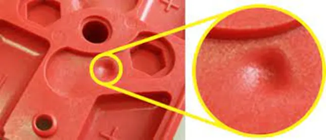
Sink mars are small craters or depressions that develop in thicker areas of the component when shrinkage occurs in the inner portions of the finished product.
Sink marks are caused when cooling time or cooling mechanism is insufficient for the plastic to fully solidify and cure while in mold. Inadequate pressure in the cavity or by excessive temperature at the gate, can also cause sink marks. Thicker areas of the component are prone to have sink mark locations.
Sink marks can be avoided by lowering mold temperature, increasing holding pressure and holding time to allow for more adequate cooling and curing. Reducing the thickness of the thickest wall section will also ensure faster cooling and help reduce the risk of sink mark.
Flash:
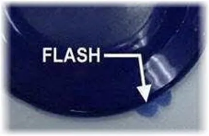
Flash is a molding defect that occurs when some molten plastic escapes from mold cavity. Typical escape routes are through parting surfaces or through ejector pin locations.
Flash can occur when the mold is not clamped together with enough force i.e., clamping force strong enough to withstand the opposing forces generated by the molten material. This allows the material to seep through. Moulds which have used exceeded enough for their lifespan are prone to flashes. Excessive injection pressure may force the plastic out through the route of lease resistance.
Increasing the clamping force pressure, to ensure the mold parts are shut during shots. Ensure that the mold is properly maintained and cleaned or replaced upon reaching its maximum lifespan. Adopt optimal injection molding conditions like speed, injection pressure, mold temperature and proper gas venting.
Plastic Component B Side Feature – Screw Boss Design Analogy:
Screw Boss Analogy:
Screw Bosses find use in many part designs as a point for attachment and assembly. Most common use of cylindrical projections with holes designed to receive screws or threaded inserts or fasteners.
One critical parameter while designing screw boss is that one should avoid merging of screw boss to sidewall so as to avoid thick sections at side walls.
Screw Boss Design parameters:
- Outer diameter of the boss:
- Draft:
- Height to Diameter ratio:
- Optimum base radius
- Boss gussets
- Coring out bottom
- Base Wall Thickness
Screw Boss Design Thumb Rules:
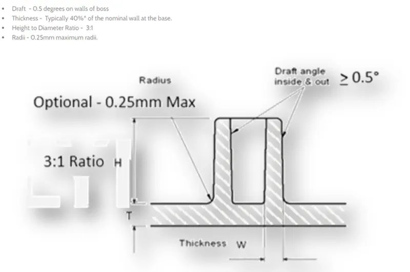
Creating Screw Boss on Given component:
As an Input, we have a Center console Coin Holder component as a solid part. We are going to design screw boss for the fixation of the component to another counterpart. Our major focus should be on following design thumb rule while picking appropriate design parameters for the given component.
First, we would calculate and define the required parameters to make it easy process in next design steps.
- Part Thickness Given (t) = 2.5 mm
- Screw boss wall thickness at the base = 40% of the wall thickness = 0.4 * t (considering per side value)
= 0.4 * 2.5
= 1 mm
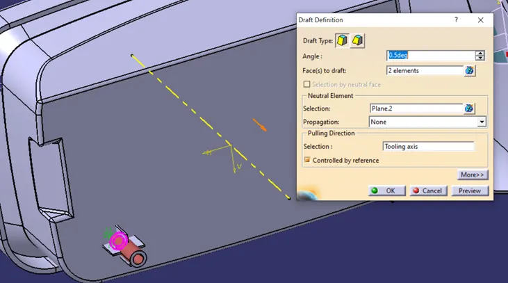
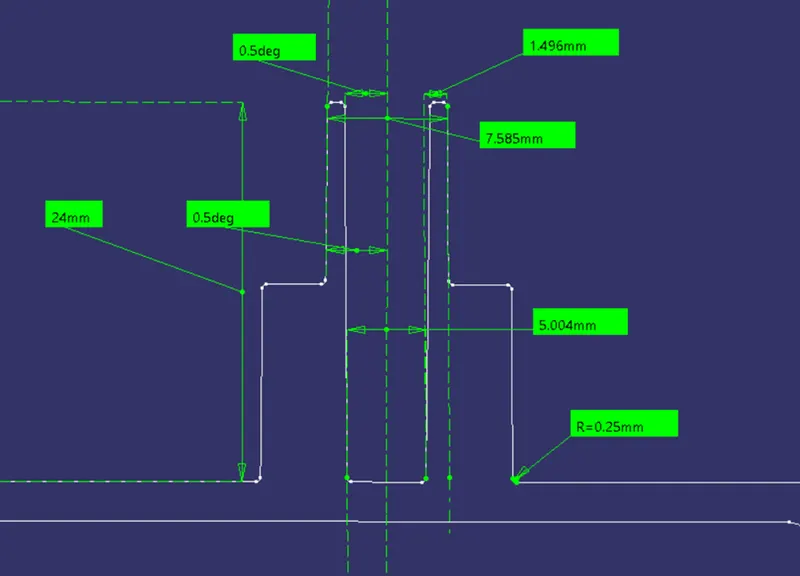
- Draft considered (default) = 0.5° per side both inner and out walls of the boss
- Inner screw insert diameter = 5mm
- Outer diameter of the Boss = Inner screw insert dia * 0.4 = 5 * 0.4 = 2 mm per side
For safe side we take 1.5 mm per side
- Height to Diameter D ratio = 3:1
- Optimum fillet radius at base = 0.25 mm
- Root thickness (Root circle diameter) = Should not exceed value of 25% of the nominal wall thickness
Applies to each side of the screw boss when taken an intersection with base wall.
Taking above parameters into consideration, we start with sketch. For that we have taken a reference plane and start a positioned sketch. And pad it to optimum height.
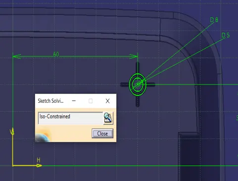
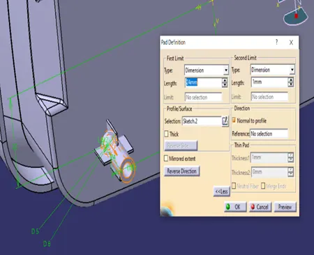
Screw boss all faces need to be drafted at 0.5° per side minimum value to clear tooling direction. Draft all faces with reference to main tooling axis.
Now that Screw boss portion is ready, we need to add ribs to our screw boss which adds stiffness to boss. Generate rib sketch and pad it according to rib design rules.
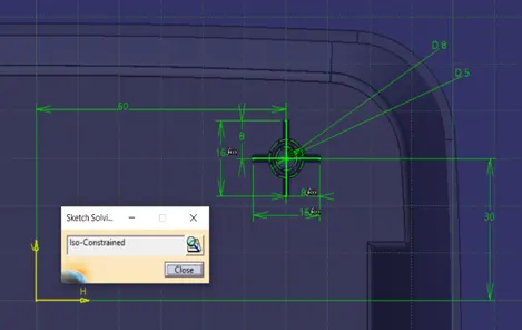
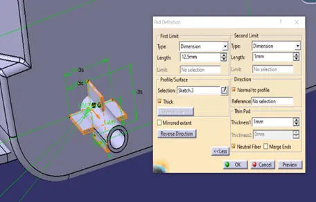
Add draft to ribs also. And then Union trim them with screw boss.
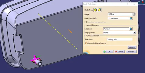
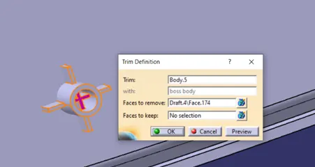
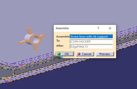
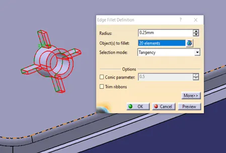
Now we can assemble that to our main component. After assembling the component, we can add optimum fillet radius of 0.25 mm to every face and to the base where the rib is connected to wall thickness. This helps in avoiding sink marks to the opposite wall.
Plastic Component B Side Feature – Doghouse Design Analogy:
Dog House Analogy:
While designing Ribs or screw boss, sometimes the counter part is at some distance up to which Ribs or screw boss cannot be designed because of the defect limitations or failure chances. In those cases where mating parts are at certain distance, Dog House serve the purpose of providing height to the Rib or screw boss.
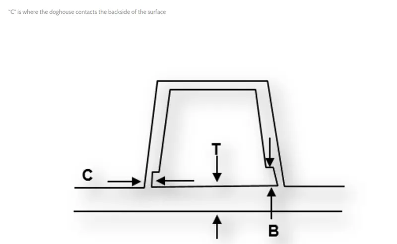
In general, Dog House is a shape having certain height from Base wall where we can mount screw bosses over the Dog house to solve the mating purpose. Here, dog house is connected to base wall. So, we have to consider the wall thickness at Dog house and Base wall portion. For Solving that purpose and to avoid sink marks to opposite surface, Dog house is designed in such a way that it’s wall thickness must be within standard rule dimension. More information we can derive from below thumb rules.
Dog House Design Parameters:
- Dog house dimensions can be taken as per requirement of length or height.
- Wall thickness at the base of the Dog house ‘C’ should be 40% or less than wall thickness.
Height of ‘B’ should be between 3.0 to 6.0 mm
Dog House Design Thumb rules:
Creating Dog House on Given Component:
Our major focus should be on following design thumb rule while picking appropriate design parameters for the given component.
Dog house has only tow critical parameters as shown in above thumb rule.
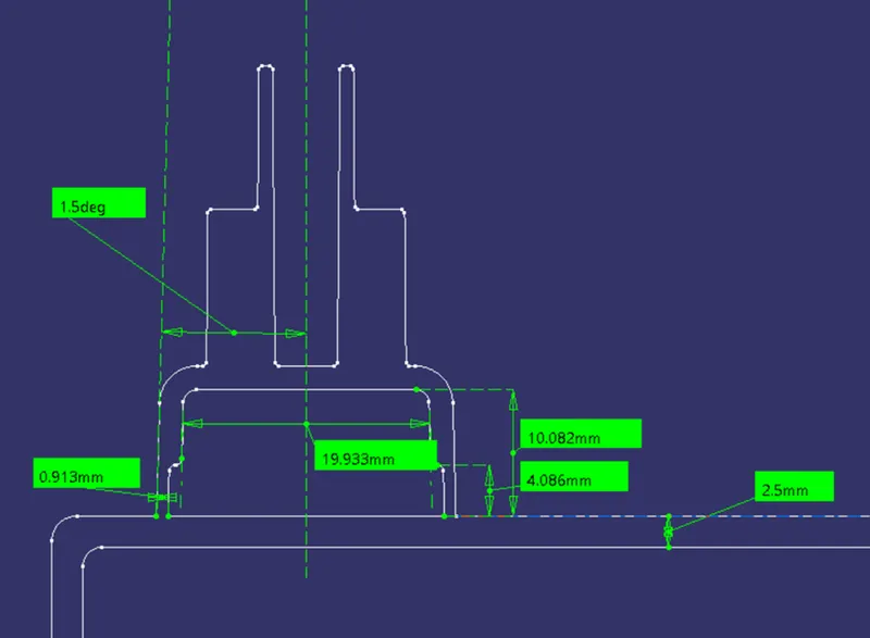
- Wall thickness at the base = 40% or less than overall wall thickness of the wall = 0.8 mm
- Height of B = 4 mm
Taking above parameters into consideration, we start with sketch. For that we have taken a reference plane and start a positioned sketch. And sweep it with reference to main tooling direction at draft of 3° similar to overall component.
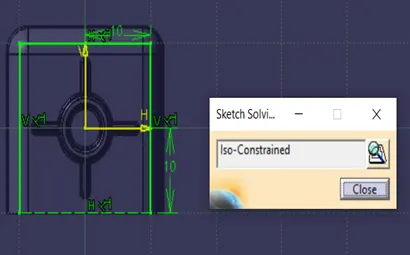
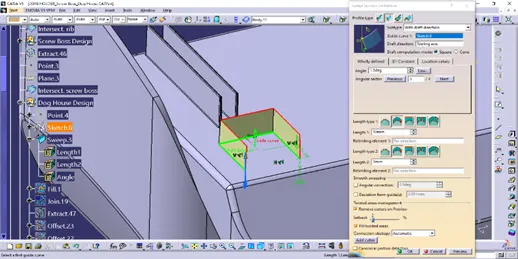
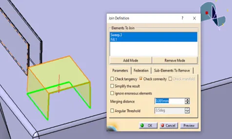
This sweep profile needs to be covered at top surface. Use boundary fill command to create top surface and join them together. Thicken that surface using part body workbench.
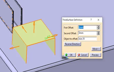
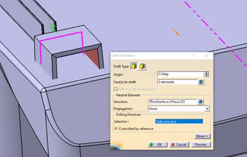
Now that we have dog house outer body ready, we can draft it with respect to side core axis as this need to clear a separate tooling axis for manufacturing purpose. Also give fillets to inner faces.
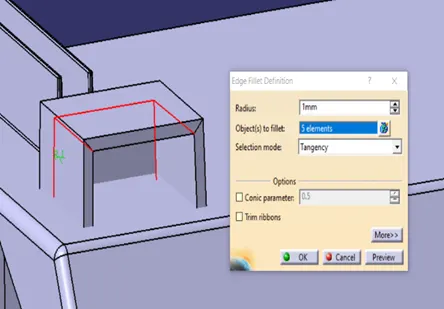
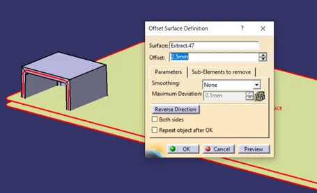
Dog house body needs to be checked for avoiding sink mars, we need to create a separate profile and split the component. Start with extracting inner face of the dog house, and offset it by 1.1 mm.
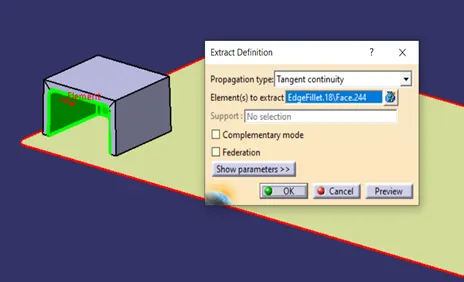
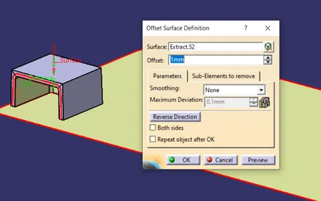
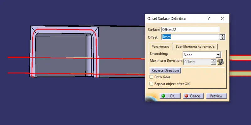
Now offset the class a bas surface and offset it by 2.5 mm. Further it is offset by ‘B’ value equal to 4mm.
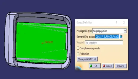
Extrapolate the offset inner face to certain value to trim with last offset surface.
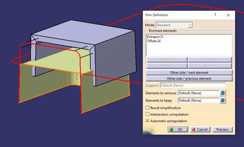
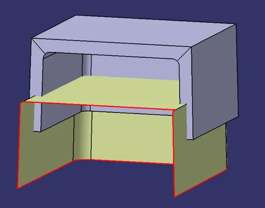
Split the doghouse body with this surface profile. Draft inner faces of the split section with respect to side core axis by 0.5° draft value. Apply appropriate fillets and the main dog house body is ready with sink mark profile.
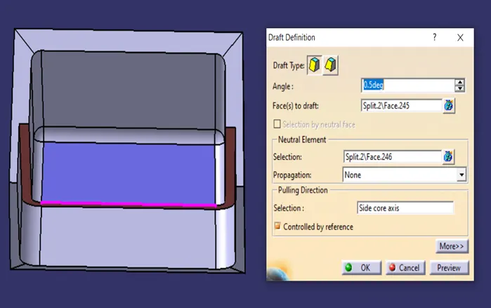
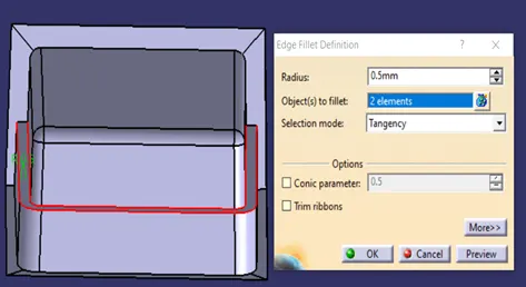
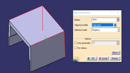
Final dog house component is as shown below.
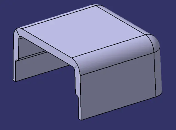
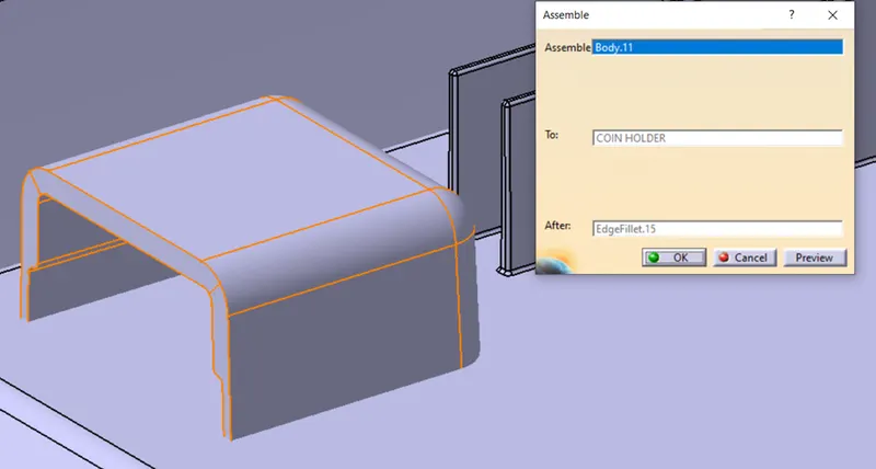
Assemble this dog house profile to main component. Apply optimum fillets to base edges.
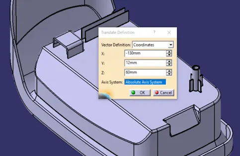
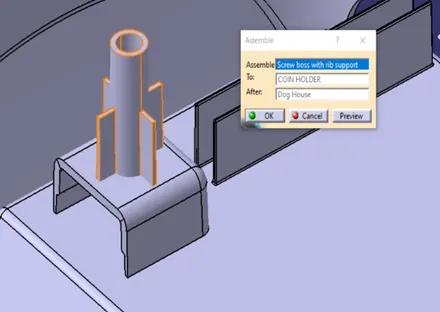
Create a copy of the previously created screw boss and translate the component on to the dog house top surface. Use translates coordinates X Y and Z value to specify the location of the screw boss. Assemble the new screw boss copy with the dog house body.
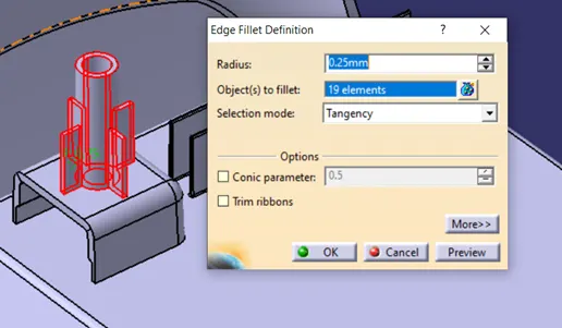
Optimum fillet radius of 0.25mm is given to screw boss edges.
Screw boss Parameters Verification with Given standard values:
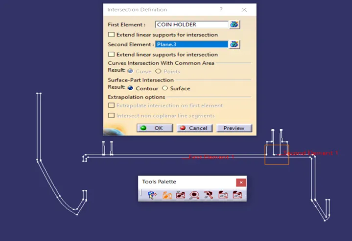
Intersecting final component with a refence plane such that Screw boss profile along with standard component wall thickness is visible. According to Standard thumb rule, all dimensions are measured and compared for conformance of the current Screw boss design.
Dog house Parameters Verification with Given standard values:
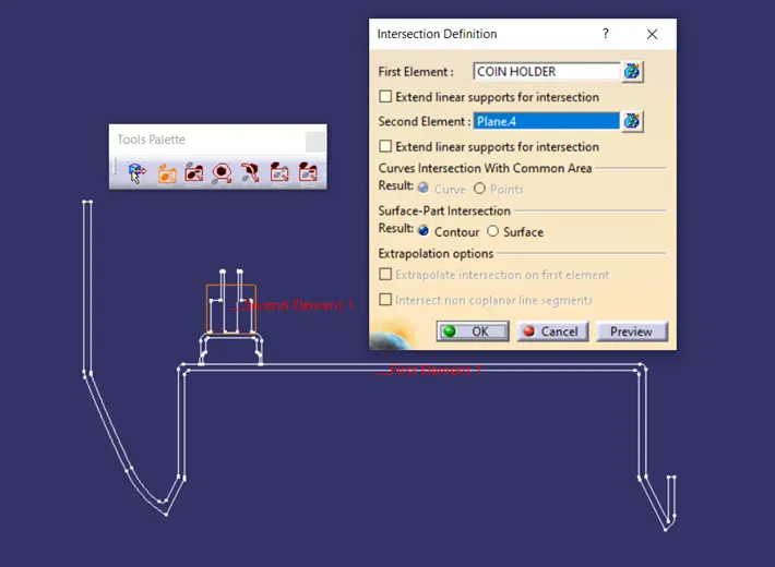
Intersecting final component with a refence plane such that Doghouse profile along with standard component wall thickness is visible. According to Standard thumb rule, all dimensions are measured and compared for conformance of the current Doghouse design.
Generating draft analysis on component:
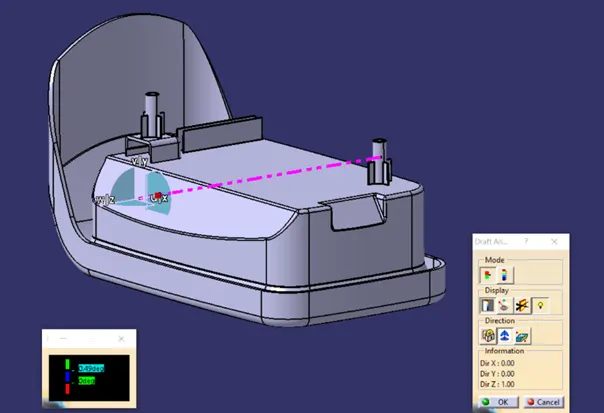
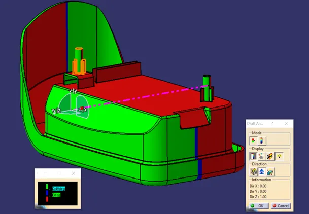
Draft analysis gives you the overall information about draft angles required with reference to main tooling axis of the component. While designing, we could give the draft angles to desired faces to clear the tooling direction. To evaluate given draft angles, we use draft analysis tool in CATIA V5.
Draft analysis steps.
- Material mode plays a vital role in generating draft analysis. The tool calculates draft angles required based upon material properties and behaviour during tooling operation. Not setting up, will give you a warning message.
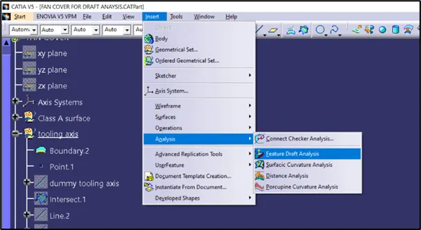
- After setting material mode, click on “Feature Draft analysis” from Insert menu. A dialogue box will be opened.
3. Use the compass option from the box, to align the current axis system with main tooling direction. It would create draft analysis with reference to tooling axis. Carefully align the axis system with main tooling axis and click on the component anywhere to create draft analysis.
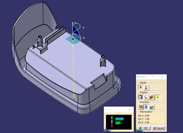
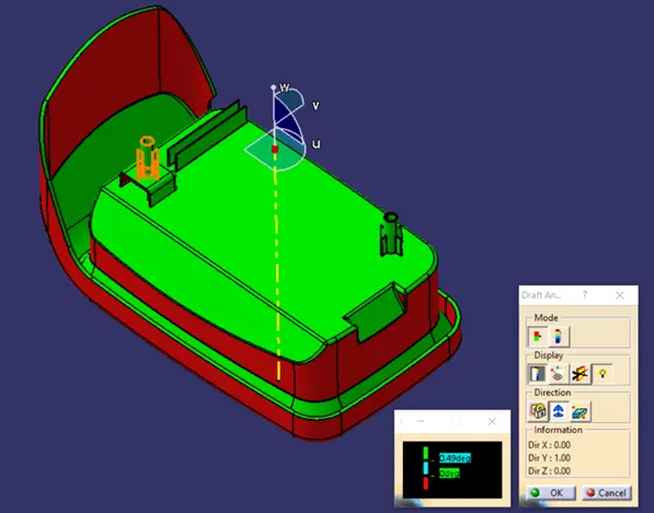
4. Moreover, this component also has to be checked for side core axis. Dog house will be checked for drafting analysis with reference to side core axis.
Conclusion:
- Brief knowledge about Plastic manufacturing defects and their types.
- Understanding Screw boss and Doghouse Design Standard Thumb Rules.
- Generating Screw boss and Doghouse on the given component.
- Used the main tooling axis for creating draft analysis on the component.
Hence, we have successfully created Screw boss and Doghouse on the given component and verified its dimensions to thumb rule standard parameters.
References: