Frequency Analysis of a rotating shaft
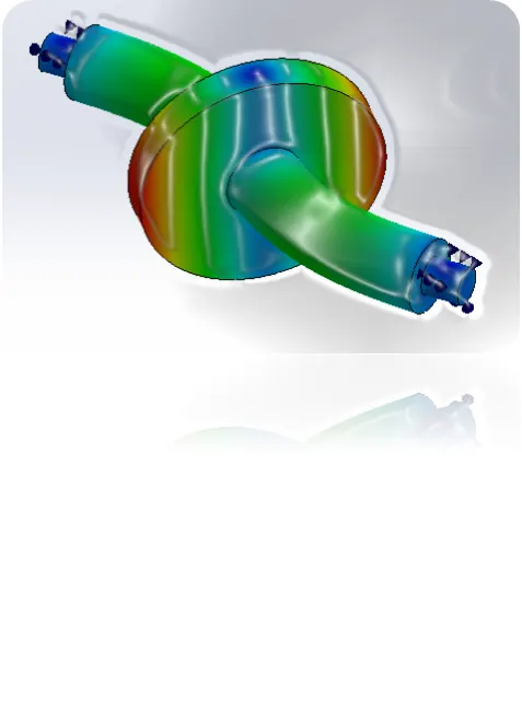
AIM: Frequency Analysis on Rotating shaft
Objective: The main objective of this project is to perform frequency analysis on shaft. Observing different mode shapes. Comparing different resonance frequency using FEA Solidworks.
Key points:
- What is frequency, mode and mode shapes.
- Geometry of shaft.
- Setting up simulation.
- Result comparison.
- Conclusion.
- References.
What is frequency, mode and mode shapes
Frequency: Frequency is the number of occurrences of a repeating event per unit of time. Usually measured in units of Hertz (Hz).
Natural Frequency: All physical structures have natural frequencies. These are the frequencies at which the structure will tend to vibrate when subjected to certain external forces. These frequencies depend on the way mass and stiffness distribute within the structure.
Resonance: Resonance is a phenomenon in which a dynamic force drives a structure to vibrate at its natural frequency. When a structure is in resonance, a small force can produce a large vibration response.
Mode: The mode is a statistical term that refers to the most frequently occurring number found in a set of numbers. Mode is found by collecting and organizing data in order to count the frequency of each result. The result with the highest count of occurrence is the mode of the set, also referred to as the modal value.
Modes are inherent properties of a structure and determined by the material properties (mass, damping and stiffness) and boundary conditions of the structure.
Mode Shapes: The deformed shape of the structure at a specific natural frequency of vibration is termed as normal mode of vibration. Each mode shape is associated with a specific natural frequency.
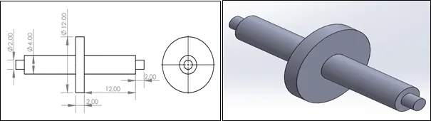
Geometry of Shaft:
For the sake of analysis, we have designed a shaft on hypothetical dimensions. As we are interested to analyze natural frequencies and modes of vibration in the system, hypothetical dimensions are considered.
Setting up Simulation:
We aim to analyze the natural frequency of rotating shaft. Also, we are interested in observing different modes of vibration. So, we have to setup a frequency analysis module using Solidworks FEA.
Pre-processing:
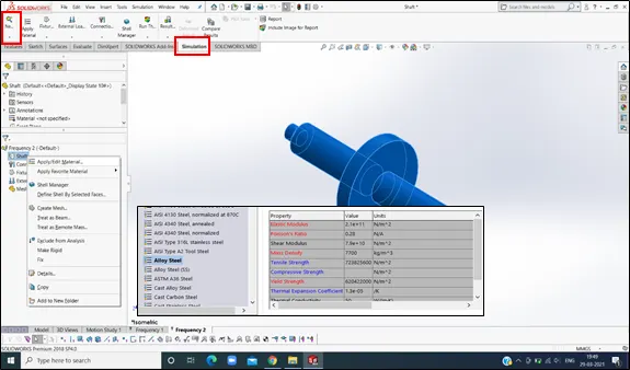
- Defining material. We have selected default material as alloy steel (same for each case) from Solidworks material library. Below image shows material properties.
Need to consider here that Alloy Steel Maximum Yield strength is 620 N/mm2.
- Open Solidworks Simulation and opt for New study.
Solving:
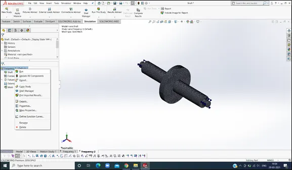
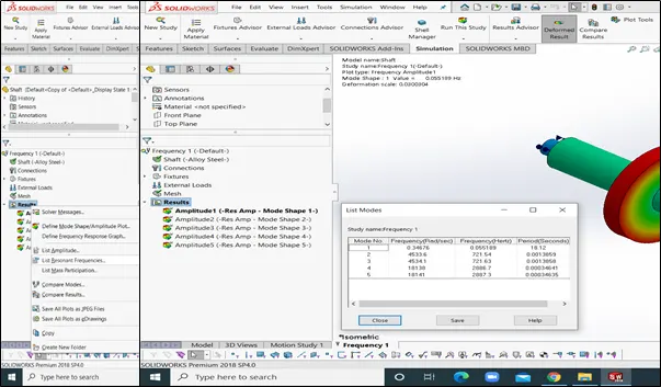
- Run the Frequency Analysis model from following screen.
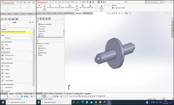
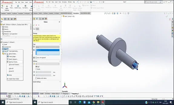
2. Next, we will apply boundary conditions. As we are simulating effects on rotating shaft, we apply bearing fixture on either side of stepped shaft.
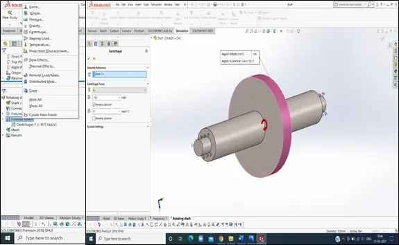
3. Apply centrifugal force of 100 rpm to shaft face to simulate rotating shaft.
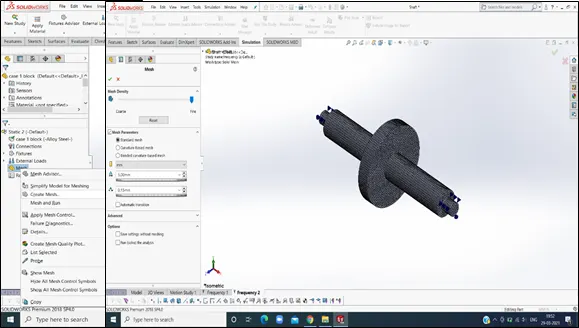
4. Next step is meshing. Meshing is also called as discretization which splits whole component into small elements. Each element is solved for defined boundary condition. Then data is interpolated for whole component.
Here mesh of 3mm is used.
5. After finalizing boundary conditions, we can run the simulation. After completing a study, we can get results for different mode shapes at different natural frequency of shaft.
Post processing:
Post processing will consist of data which we required as output of simulation study. Here we are interested in observing different modes of vibration for rotating shaft. Also, we get different resonance frequencies for the given case.
Results Comparison:
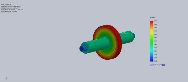
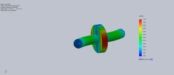
Mode:1
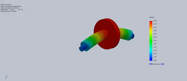
Mode:2
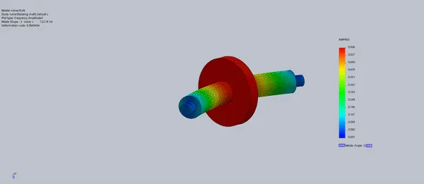
Mode:3
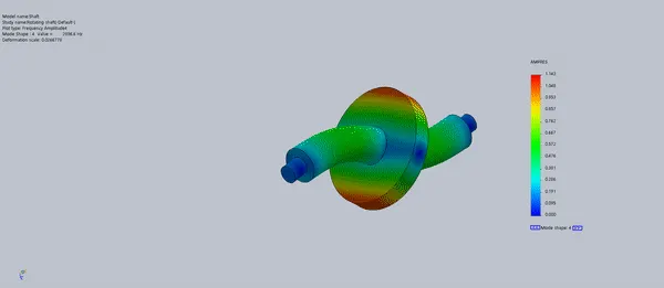
Mode:4
Mode:5
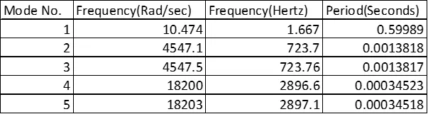
Resonance Frequencies obtained:
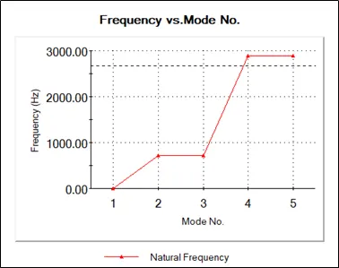
Frequency Response Graph (Frequency vs. Mode Number)
Conclusion:
- The frequency varies for different mode shapes. Amplitude is directly proportional to frequency inducing the resonance.
- 1st Mode is mechanism mode. The Shaft has one rotational degree of freedom about its own axis. Hence first mode of natural frequency is shown as rigid mode having natural frequency equal to zero hertz (or less than 1).
- 2nd /3rd Mode have same natural frequency, but only difference is mode 2 oscillates in ‘Y’ direction while mode 3 oscillates in ‘Z’ direction.
- 4th /5th Mode have same natural frequency, but only difference is mode 2 oscillates in ‘Y’ direction while mode 3 oscillates in ‘Z’ direction.
- Mode shapes and natural frequency values give the direction in which external frequency should be applied. But generally, external excitation not controllable while under working environment. So, we need to alter the natural frequency of the part by varying material properties and/or working conditions.
References: