Analysis on a Plate with hole
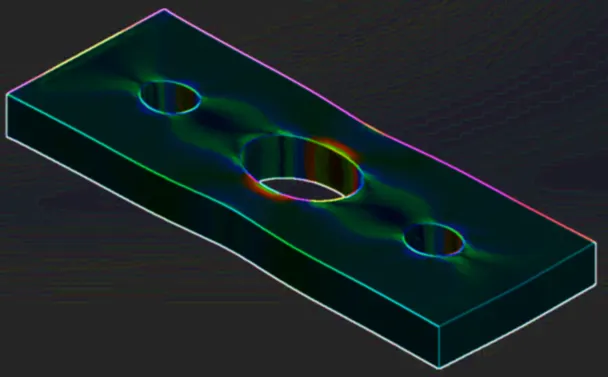
AIM: Analysis on a Plate with hole
Objective: The main objective of this project is to Simulate a plate having hole, Effects on stress, strain and displacement when number of holes are increased. Comparing both cases results using FEA Solidworks.
Key points:
- Geometry of Plate.
- Setting up simulation.
- Result comparison.
- Conclusion
- References
Geometry of Plate:
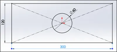
- Plate having center hole only.
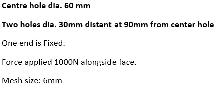
- Plate having Centre hole and another two holes of dia. 30mm equidistant from center hole at 90mm
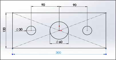
In Both cases, geometry is drawn in Solidworks 3D module and given plate thickness of 30 mm for each case.
Setting up Simulation:
We aim to analyze effect of multiple holes on a single plate having same dimension, same material and same loading conditions. We are using static analysis here.
Pre-processing:
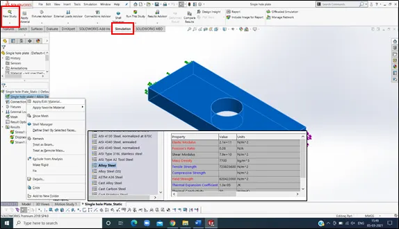
- Defining material. We have selected default material as alloy steel (same for each case) from Solidworks material library. Below image shows material properties.
Need to consider here that Alloy Steel Maximum Yield strength is 620 N/mm2.
- Open Solidworks Simulation and opt for New study.
Solving:
- Run the static Analysis model from following screen.
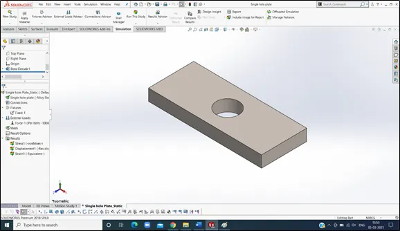
2. Next, we will apply boundary conditions. Fix one end of plate with respect to its cross-sectional plane.
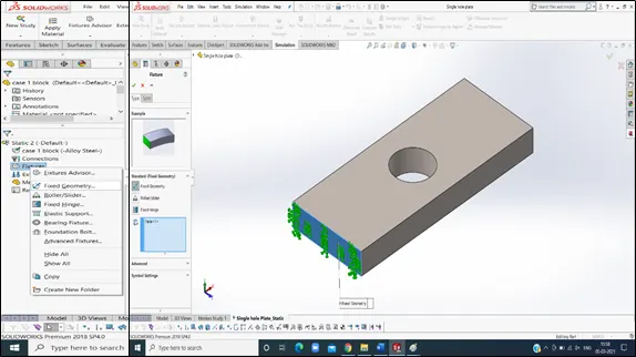
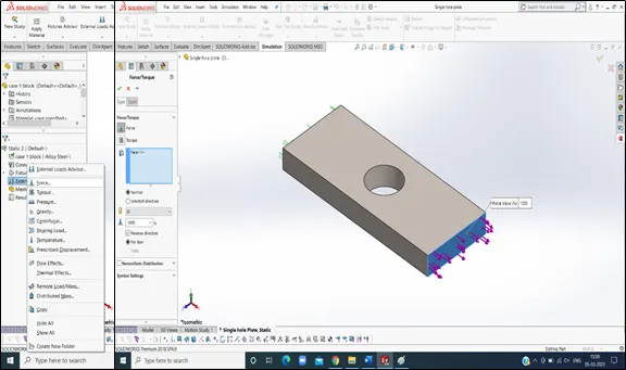
3. Here applied force is 1000N for each case.
4. Next step is meshing. Meshing is also called as discretization which splits whole component into small elements. Each element is solved for defined boundary condition. Then data is interpolated for whole component.
Here default mesh of 6mm is used.
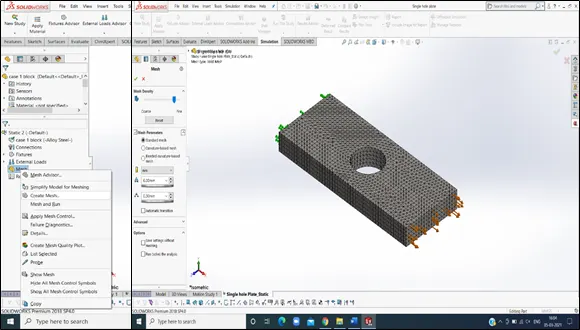
5. After finalizing boundary conditions, we can run the simulation. Here it will give values appropriate for Von-mises stress, Strain and displacement.
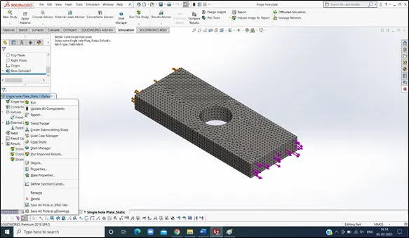
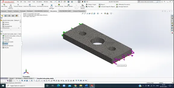
Below Image shows 3D meshed model of another plate having multi holes.
Post processing:
Post processing will consist of data which we required as output of simulation study. Here we are interested in Comparing Stress, Strain and displacement values for both cases. Results are discussed below.
Case 1: Plate having Single hole of dia. 60mm at center of the plate.
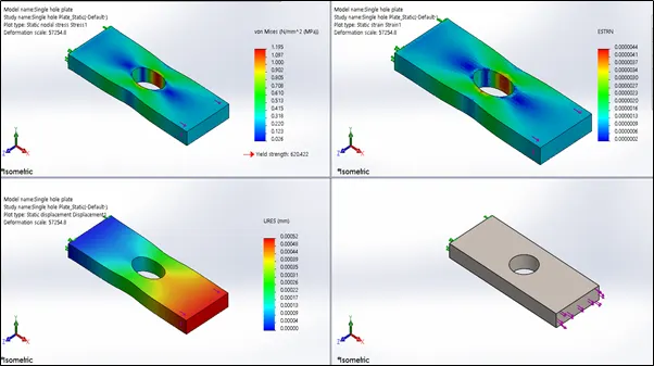
Observation:
Max Von Mises Stress: 1.195 N/mm2
Displacement: 5.2 X 10⁻⁴ mm
Strain: 4.4 X 10⁻⁶
Weight: 7.66 kg
Case 2: Plate having Center hole of dia. 60mm and two holes dia. 30mm equidistant at 90 mm from center of plate.
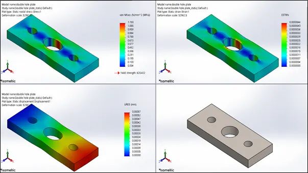
Observation:
Max Von Mises Stress: 1.150 N/mm2
Displacement: 5.7 X 10⁻⁴ mm
Strain: 4.4 X 10⁻⁶
Weight: 7.34 kg
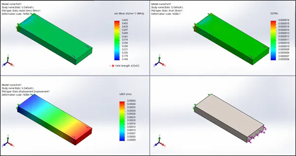
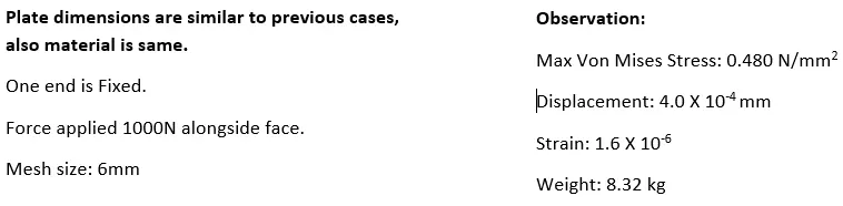
For the sake of analyzing effect of hole in the plate, I’ve also tried same simulation with plate without hole.
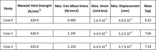
Summary of results obtained:
Conclusion:
- In both cases, stress, strain and displacement induced is under Yield stress limit. Both components survive under given loading condition.
- Among two cases, there is negligible difference between obtained values. While in case 2, stress produced is less than case 1. Also, displacement in case 2 is more than case 1. Hence satisfies inverse relation between stress and displacement.
- Stress propagation start from the circumference of hole itself due to sudden change in area of cross-section.
- For simple plate, stress produced is very less and at fixed end only. Ultimately, geometric non-linearity tends a component to fail under very low forces.
References: