MBD Simulation on a Piston Assembly
Objective:-
- To design parts of Piston Assembly and Assemble them by providing the required constraints.
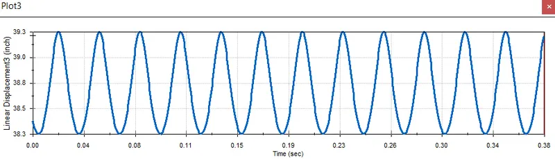
- To plot graphs at 3 different conditions between Time and linear displacement of the Piston Head.
- To conclude results by observing the model and graphs.
Introduction:-
- We have to assemble the piston assembly by designing all the required parts
- Piston assembly consists of different parts such as:-
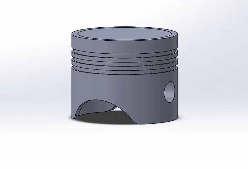
- Piston Head
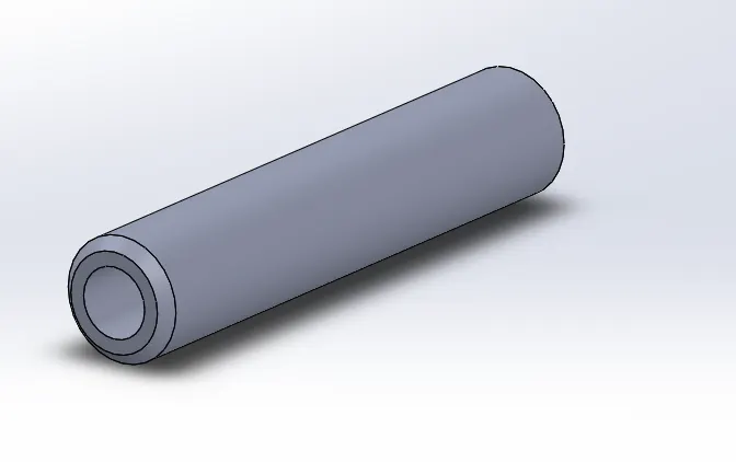
- Gudgeon Pin/Wrist Pin
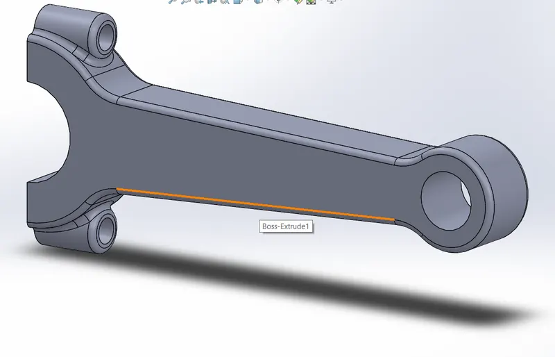
- Connecting Rod
- End Cap
- Crankshaft
- The Piston assembly is based on the principle is that when the fuel burns it produces energy which forces the piston to move and as the piston is connected to the crankshaft through the connecting rod and gudgeon pin it the motion of the piston produces a rotatory motion of the crankshaft i.e., it is a conversion of rotatory motion into reciprocating motion and vice versa.
Theory:-
- In this model, we designed all the components using Solidworks part design then first we constrained the crankshaft in the assembly in such a way that its Front Plane is coinciding with the Front Plane of the Assembly, so it has left with only 3 degrees of freedom ( it can move along X-axis, Y-axis, rotate around Z-axis)
- As though we only need the rotation along one axis which is the Z-axis, so then we coincided the center axis of the crank with the top plane so that it won't have any linear motion left along Y-axis then we coincided the Centre axis of the crankshaft with the Right plane so that the linear motion along the X-axis also got fixed
- So in this way, we constrained the crankshaft so that it will have only a rotatory motion along the Z-axis.
- Then we constrained Endpin with the Connecting rod by coinciding their faces, and axis.
- Then we coincided the Axis of the Connecting rod with the crankshaft and gave a distance mate between the inner face of the crankshaft and connecting rod of 1mm.
- And then Similarly we contained the piston head and gudgeon pin too.
- Then we did the motion analysis by using the given conditions and plotted graphs for different offsets of the piston head.
Piston Head:-
Gudgeon Pin:-
Connecting Rod:-
Endpin:-
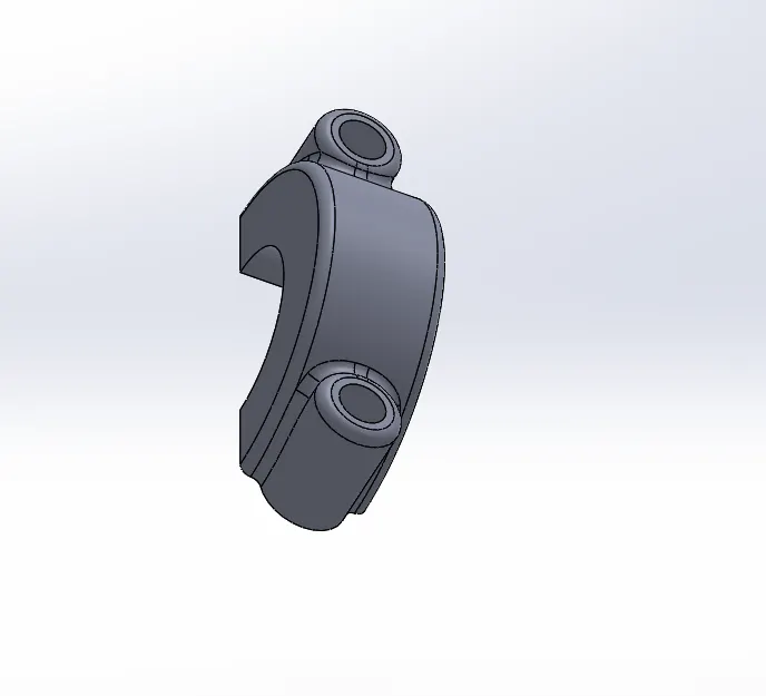
Crankshaft:-
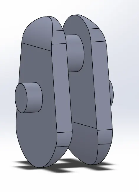
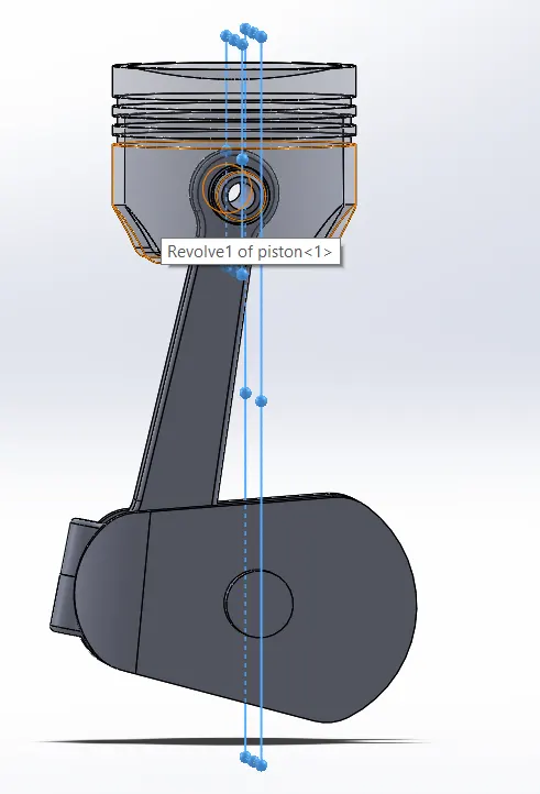
Full assembly at 0mm offset:-
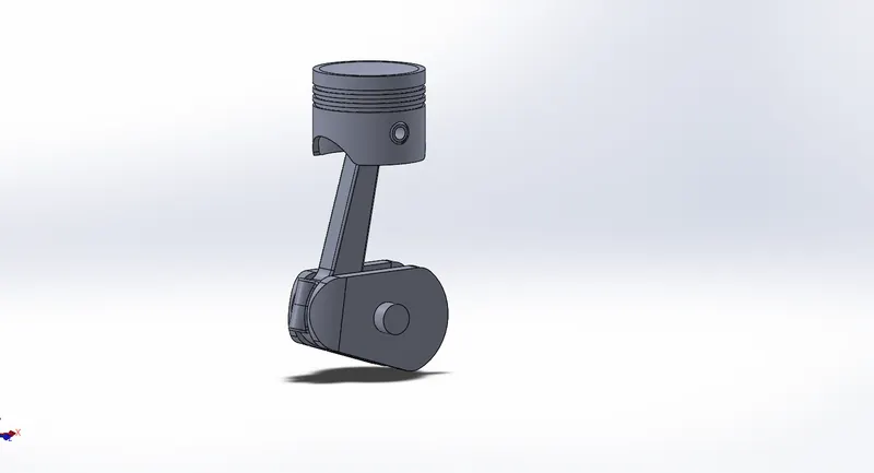
Full Assembly with 10 mm positive offset when the crank is in anticlockwise direction:-
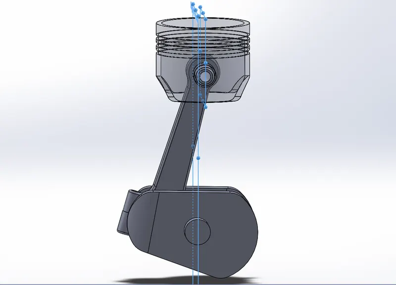
Full Assembly with 10 mm negative offset when the crank is in anticlockwise direction:-
Results:-
- Case 1:-
- when the crank is rotating in an anticlockwise direction and the wrist pin is given 0mm offset.
- we use the 7200 fps frame rate
- we use precise contact.
- Plot 1:-
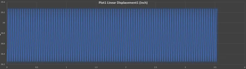
- Case 2:-
- when the crank is rotating in an anticlockwise direction and the wrist pin is given 10mm negative offset.
- we use the 7200 fps frame rate.
- we use precise contact.
- Plot No.2:-
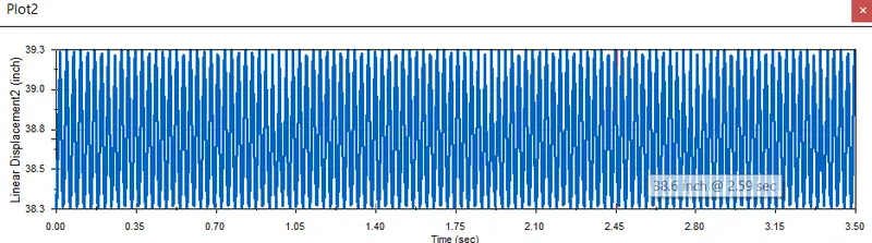
- Case 3:-
- when the crank is rotating in an anticlockwise direction and the wrist pin is given 10mm positive offset.
- we use the 7200 fps frame rate.
- we use precise contact.
- Plot No.3:-