Week 3 - 2D meshing for sheet metal
Objective:-
- our main objective in this modal is to create a mesh
- for that, we need to create a 2d mid surface of the given modal because as we will be doing the 2d mesh
- before and after creating the mesh by using appropriate tools we need to do geometry clean up
- so that we get a perfect surface and as a result a perfect mesh
- with no failing elements and proper surface capture
- and thickness assigned to that mesh as equals to the modal
- so that the mesh turns into a 3d modal equivalent mesh
Introduction:-
- we got a modal of the hood of a car which is also called the bonnet of a car in Commonwealth English the hood is the hinged cover over the engine of motor vehicles. Hoods can open to allow access to the engine compartment or trunk (boot in Commonwealth English) on rear-engine and some mid-engine vehicles) for maintenance and repair.
- hoods are generally made of sheet metal
- The manufacturing process of the hood comprises the following steps:
- (1) blanking,
- (2) stretch forming,
- (3) trimming and punching,
- (4) deburring,
- (5) welding,
- (6) grinding,
- (7) painting,
- (8) baking,
- (9) polishing and waxing, and
- (10) coating
- In this modal, the Hood consists of 3 components
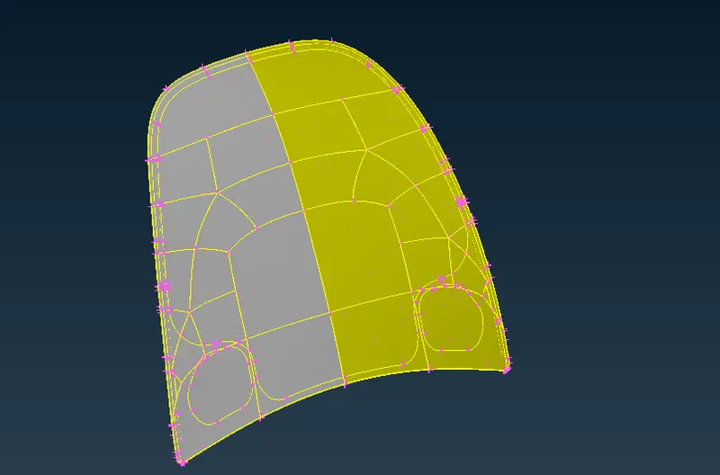
- outer extract(uppermost shinner part)
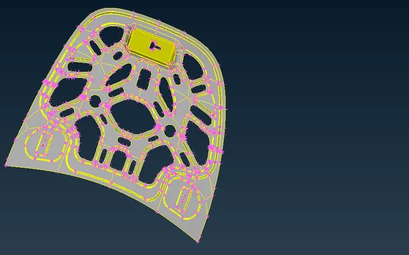
- inner extract(BIW of hood)
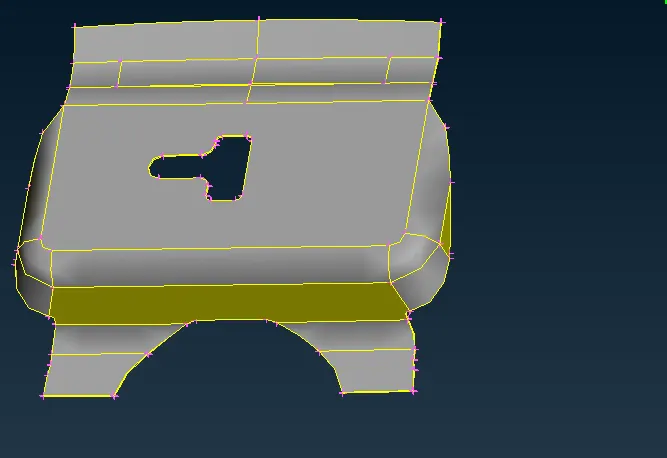
- latch reinforcement
- 2 hinge reinforcement
- so for this modal, we will be creating the mesh of the hood of the car which is basically the preprocessing step in CAE by using CAE BETA systems (ANSA)
- for this, we will be first inserting a Command after opening the ANSA v19.1.7 to get the hot points(nodes) and Cons visible which is "-performance_mode 3"
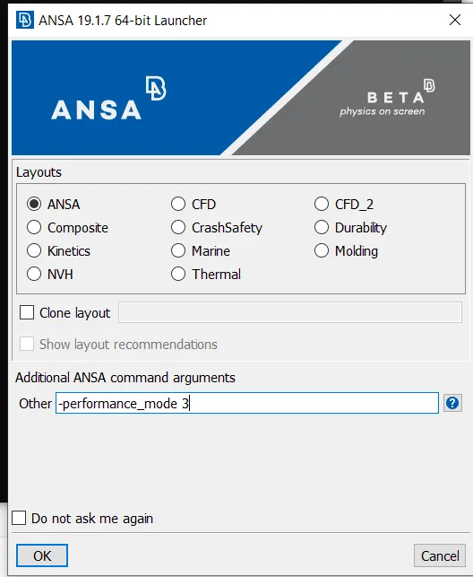
- then after this, we will open the given modal through the "open" option in ANSA
- then we will separate the different parts of the hood in different locks by using an appropriate tool
- then we will create the mid surface of each part by using an offset tool
- then we will again check for missing surfaces and geometry irregularities
- then we will mesh each part one by one
- then we will check for the quality of the mesh and finally, we will assign thickness to it
THIS IS THE MODAL RECEIVED:-
Outer extract
Inner extract
Latch Reinforcement
Hinge Reinforcement
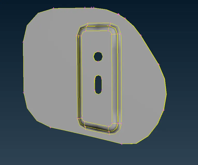
- So after measuring the thickness of the modal at various different positions between 2 hot points using the "measure" tool
- it came out to be that the thickness of the modal is uniform through the modal which was 0.75 mm
Theory:-
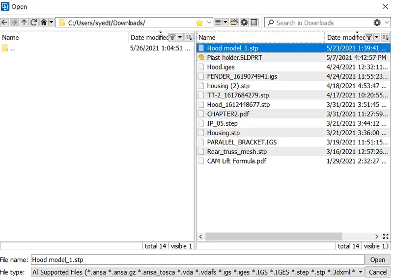
- IN this modal we first opened the modal after opening the ANSA v19.1.7
- File --> open then selected our modal
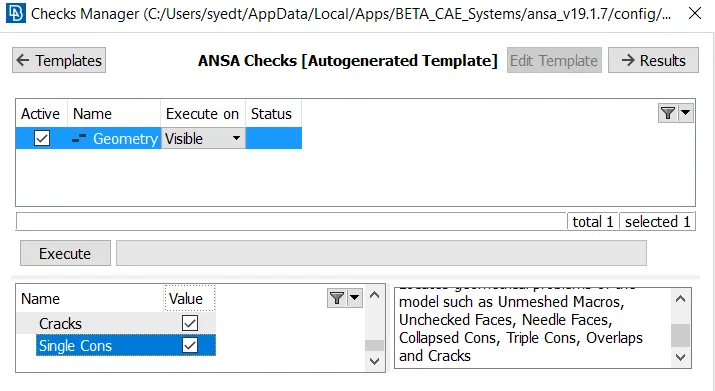
- then we did the geometry check using the Checks tool
- Checks--> geometry then we clicked on to execute
- and we found these errors in the geometry
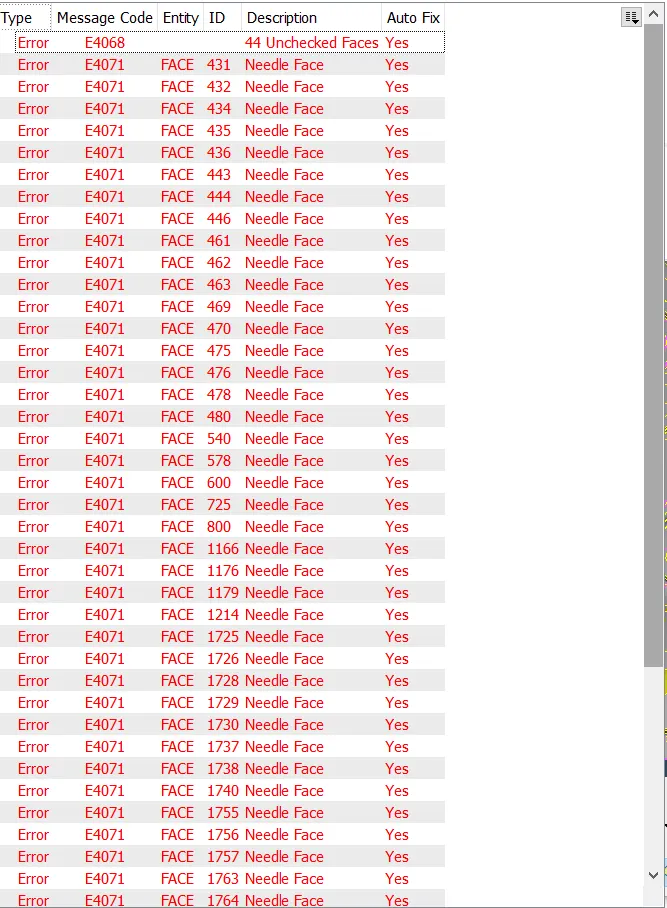
- Then to fix them we used an option called "fix" in the "Actions"
- that's how all the errors got fixed
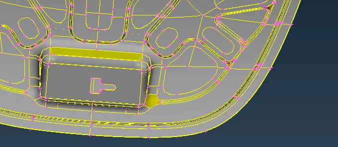
- then we moved to fix the orientation of the given modal since all the faces should have the same orientation
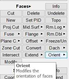
- these were some of the orientation errors in the geometry that we fixed using the "orient" command in the "faces"
- after fixing all the geometrical issues we moved towards separating each component in a different lock so that our work becomes easier
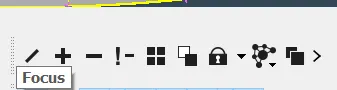
- to do that we used the "focus" tool
- in which we used "or", "and", neigh" commands
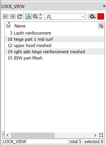
- and after separating the components into different locks using store lock and lock manager
- this is how it looked
- then we moved towards creating the mid surface of each component
- for which we measured the thickness of the geometry at various positions between two hot points using the measure tool
- then we did the mid surface as the geometry was uniform in thickness we can do the midsurfacing at one shot only
- by using the mid surface command in the "faces" toolbar

- or we can also use the offset tool in the faces toolbar
- then after successfully creating the mid surface using the offset tool
- we locked the mid surfaces into different locks as the mid surfaces were inside the geometry
- that's why we have to use the "focus" toolbar too to get them into different locks
- after that, we moved towards meshing the mid surfaces one by one
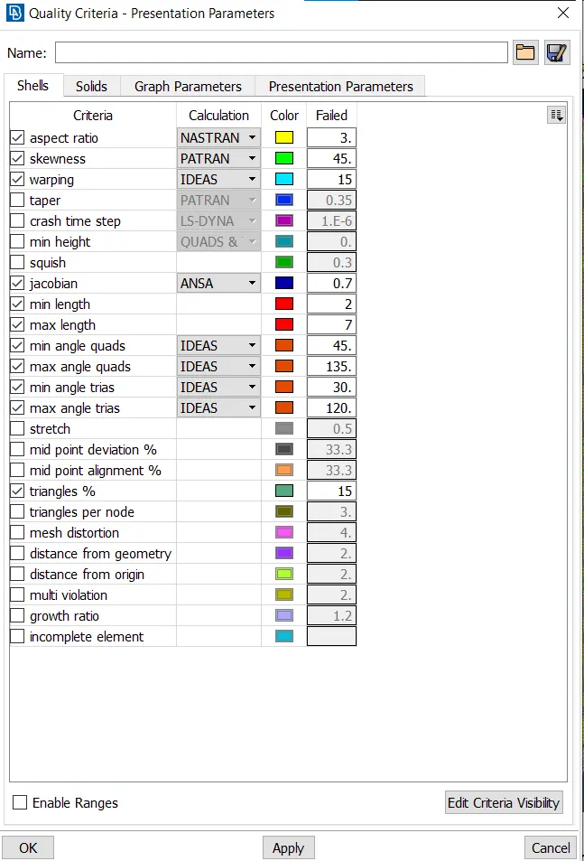
- for which we first inserted the values for the quality criteria as to how it was given to us
- to do so we opened quality criteria from utilities
- then we inserted these values
- then we clicked on %elements and details of elements as all details in the presentation parameter
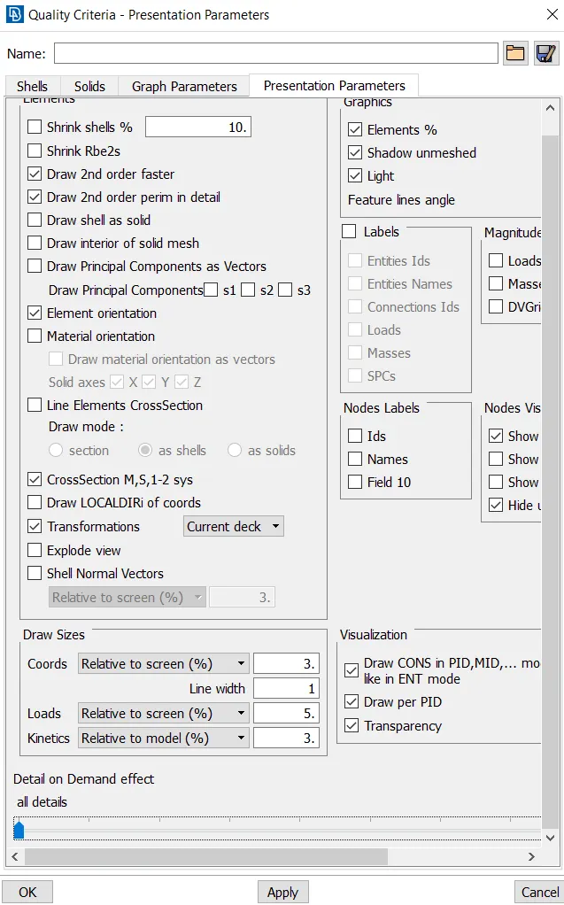
- then clicked on apply and then ok
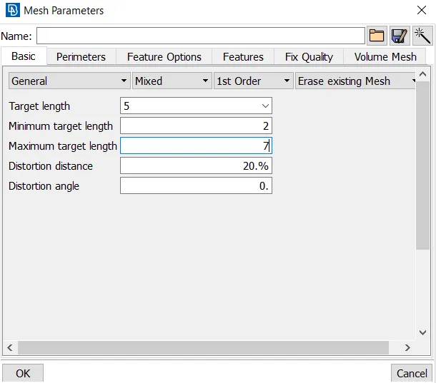
- then opened mesh parameter through the utilities there we inserted size and type of elements
- and maximum-minimum sizes of elements
- for that, we first have to switch to mesh mode by clicking on mesh in the module toolbar
- and there we used the best tool in the mesh generation toolbar to mesh the mid surface
- and then we fix the quality using the reconstruct and smooth tool available in the shell mesh toolbar
- and then we used the hidden mode to see the failing elements
- and we fixed all the failing elements by using the split (edge, node), paste, and join tools available in the Elements toolbar.
- and hence that's how we got a mesh with zero failing elements
- for meshing the Inner extract we used the copy option in the transform tool present in the utility bar
- because the inner extract part is symmetric along one axis so we just meshed the 1st half part of the inner extract and then we used the transform tool
- for which we first deleted the other half of the CAD modal of inner extract because as we know in ANSA the mesh gets attached to the surface so if we will try to copy the mesh to the other side the surface will also get copied too, for which we have to first delete the first half of the surface
- for which we used delete tool in the faces toolbar
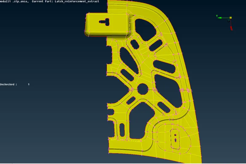
- after doing this we meshed this part of the inner extract and eliminated all the failing elements by using appropriate required tools
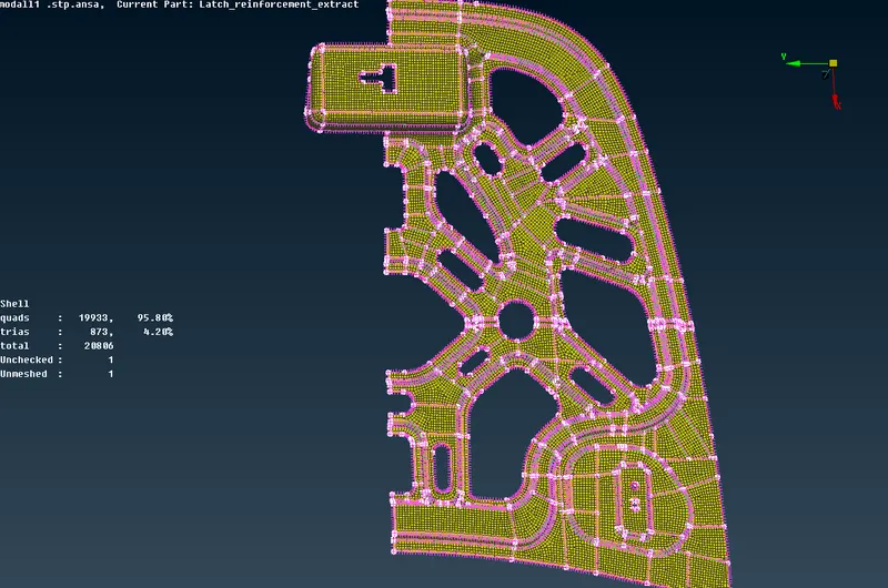
- after this, we used the transform tool (copy)
- after selecting the copy option we selected the entities that we have to mirror to the other side
- then we selected symmetric
- and in symmetric we selected the 3 point plane and then we selected 3 extreme endpoints on the current half mesh
- then click on the middle mouse button and that's how we got the full part mesh of the inner extract part
- and we did some required topology and geometry clean up
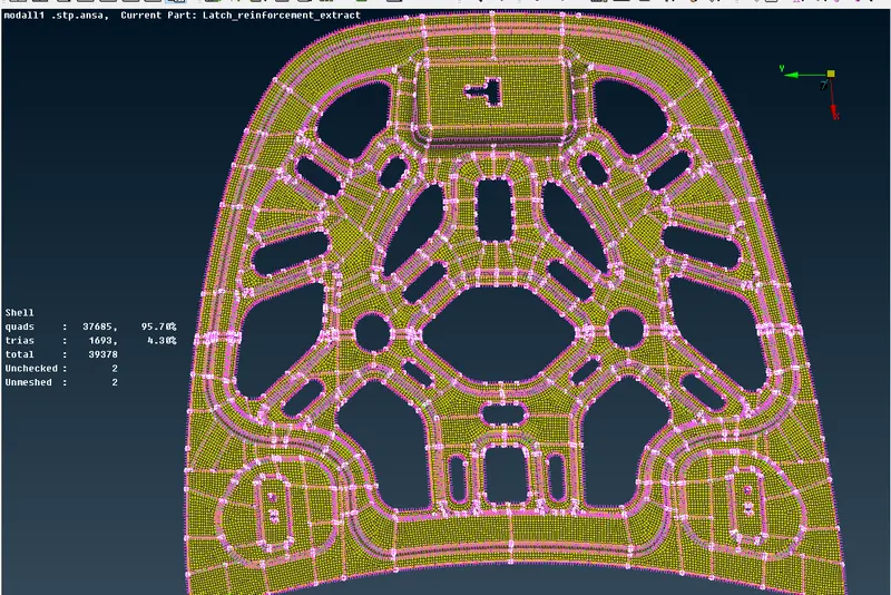
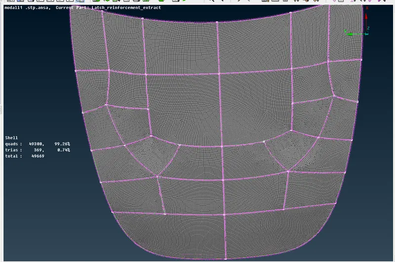
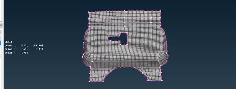
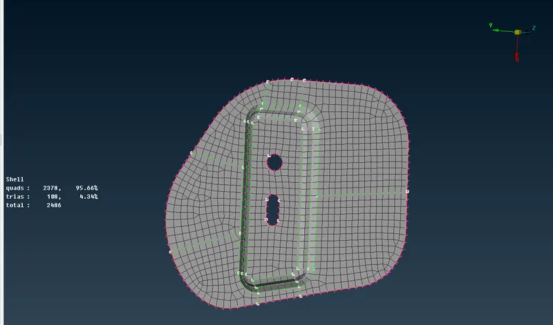
- Now we just have to assign a property to all of these components and then the thickness
- for which we clicked on setup ID in face toolbar
- then there we selected all the elements and then clicked on the middle mouse button
- then we created a new property
- and assigned thickness as 0.75
- and named the property as "hood_0p75"
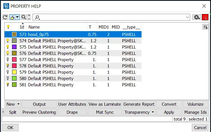
Conclusion:-
- we learned a lot in this modal like how to use many different tools such as
- tools in focus such as and, or, neighbor, lock, etc
- learned how to do mid surfacing by offset method or automatic mid surfacing
- then we learned how to use the transform tool to reflect the cad and the elements along any axis
- we learned how to use different tools to fix geometrical errors
- we learned how to use different tools to have a better mesh quality such as swap, split, join, reconstruct, paste, etc