Week 12:Project 2-Meshing of Rear Wheel Holder challenge
Situation:-
- Here the situation is that we got a Modal in (.hm) format of a rear-wheel holder of a car so we imported the modal using import modal option in the Altair Hyperworks
- A rear wheel is mostly situated at the backside of the car or say on the back door of a car
- the rear wheel holder is used for holding a spare wheel on it
- for creating the rear wheel holder mostly sheet metal is used
- here we a modal of a rear-wheel holder and we have to create a 2d mesh of it
- first, we downloaded the file given in the challenge
- then after observing the surfaces we come to know that a lot of surfaces are missing so we have to create them too
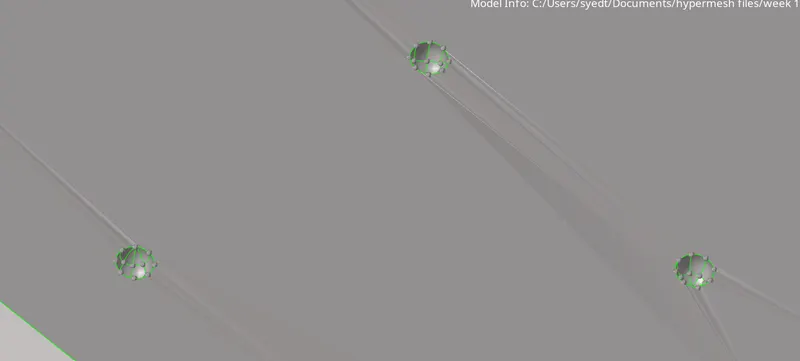
- then we saw there are a lot of small buttons which are so small in size that after meshing elements of those surfaces will fail so we have to delete them too
- this, the surface of the rear-wheel holder has a lot of uneven surfaces and edges so we have to be careful about that too
- this a very huge surface so we have to think about dividing the modal into several simple surfaces through cut lines
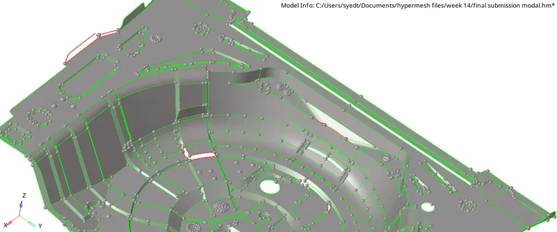
- this is the modal that we received
Tasks:-
- After importing the modal into HyperWorks as a modal file (.hm)
- we have to turn on the geometry color mode to "by topo mode" so that we can comfortably see all the lines such as
- the red lines representing free edges or fixed edges
- green lines representing the shared edges with no gap in between two surfaces,
- the yellow line representing that the edges are being shared by more than 2 surfaces
- blue line representing the suppressed edge

- after observing the whole surface of the rear wheel holder
- we found out that a lot of surfaces are missing and some surfaces are overlapping
- so we have to fix them by
- creating the missing surfaces and by eliminating the overlapping surfaces
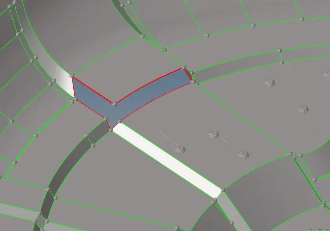
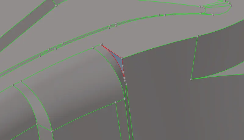
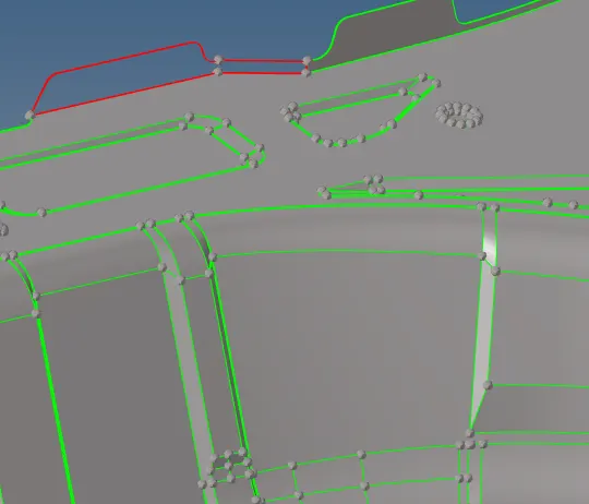
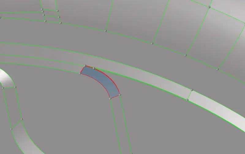
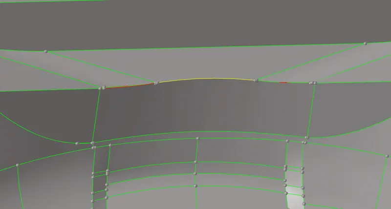
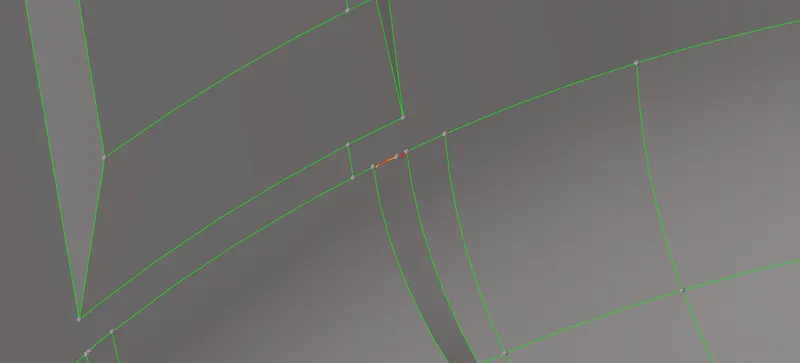
- So first we have to fix these missing and overlapping surfaces by using appropriate tools such as ruled or filler surfaces or by deleting some surfaces
- after fixing all the missing and other irregularities of the surface
- we have to create a mid surface of the given modal
- so the modal has a very uniform thickness throughout all the surfaces
- we have to measure the thickness of the modal in different sections so that we can confirm that it is a uniform thickness modal or not
- so we have to measure thickness by using the "project nodes" tool
- then after observing that the modal has a uniform thickness we can proceed by using a simple manual mid surfacing of all the surfaces at once only or otherwise if it's not uniform then surface by surface (surfaces which are having same thickness mid surfacing only them together)
- after extracting the mid surface we have to remove all the small buttons by deleting them and creating a flat surface there
- these are the small buttons
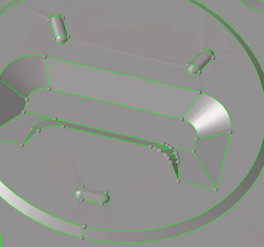
- after fixing all the surfaces and lines we got this mid surf by using the offset option in the surface tool
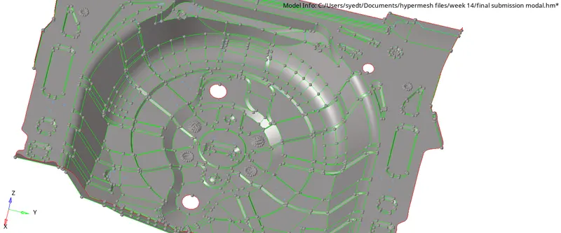
- before creating the mid surface we have to first create a component as "mid_surf" to duplicate all the surfaces to this before offsetting them.
- after creating the mid surface we have to create a proper flowing 2d mesh of the surface using the given criteria file settings
- after meshing the surfaces we have to fix all the failing elements by using the appropriate tools
- then we have to assign thickness to the created 2d mesh of the surface
Actions:-
- So first we created the mid surface by using different tools
- since after importing the modal we found out a of geometrical faults in the modal so that we deleted the improper surfaces and then created a better surface over there using tools such as "ruled" "filler surface"
- for importing we used this
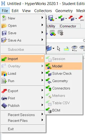
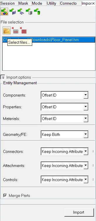
- after importing the modal we fixed the missing and overlapping surfaces deleted the small unrequited buttons
- by first deleting them and then creating a surface over there

- we used the project tool to project nodes to the surface and to then by using them we calculated the thickness and based on that thickness we offset the surfaces
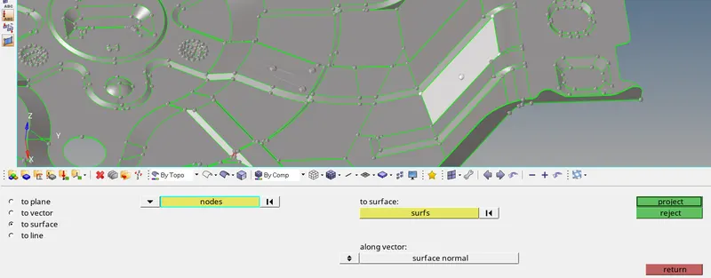
- after fixing all the surfaces we created the mid surface by using the offset option in the surface edit tool
- but before offsetting the surfaces we created a component as "middle surface"
- to duplicate all the surface before offsetting because in the offset tool the original surface gets offset without creating a copy for the parent geometry so to keep parent geometry we first duplicated the surfaces then clicked on offset
- to create a new component we followed this way
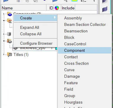

- after creating we started to offset surfaces to that "middle surface" by duplicating them
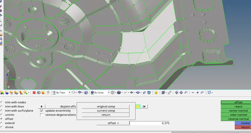
- after selecting the surface we clicked on surf bar in the offset tool there on "duplicate" then to current component and our current component was "middle surface"
- Now after getting the mid surf we moved towards meshing of the surface
- by using the 2d automesh tool
- so this is our major role "meshing of the surfaces"
- we used the given criteria file settings to mesh the component and to fix the failing elements.
- we inserted the values for the criteria file by opening through "preferences"--> "criteria file settings"
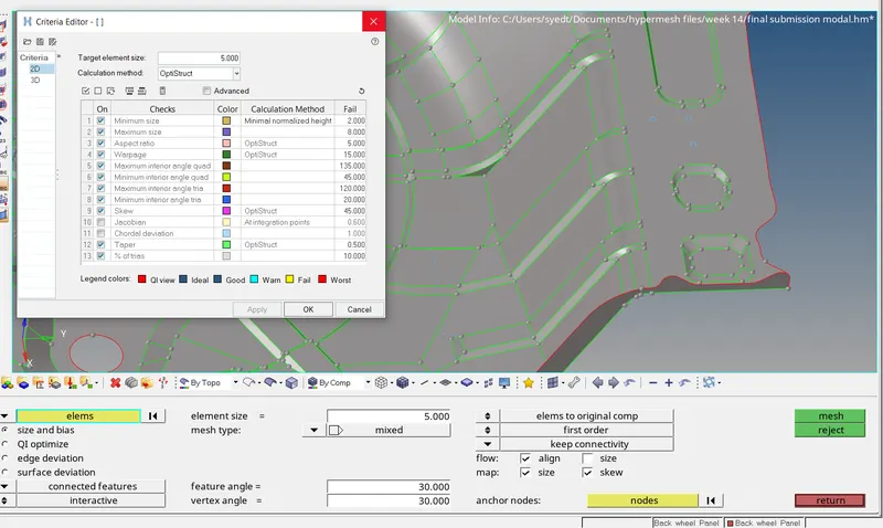
- we used an element size of 5
- then we started meshing the component surface by surface
- and fixing the failing elements after meshing the particular surface
- so we fixed the failing elements by using the element quality tool in the 2d panel
- for whatever the element was failing such as for skewness, aspect ratio, the maximum size, etc
- we used the appropriate tools to fix them such as by
- remeshing the failing elements and their surrounding elements
- then by element optimization in the element quality
- then to decrease the tria concentration in the mesh and to make a good flow of trias and to eliminate the opposite trias in the mesh we used the drag tria tool and combine tria for combining two adjacent trias into quad elements
- we changed the element colour mode to element quality so that it helps to see the failing element and the reason for their fails too
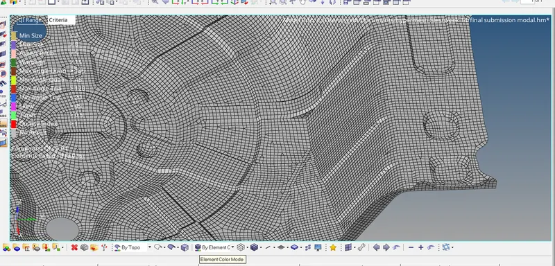
- to create a better mesh flow we eliminated all the falling elements and reduced tria concentration by using the Element quality index tool
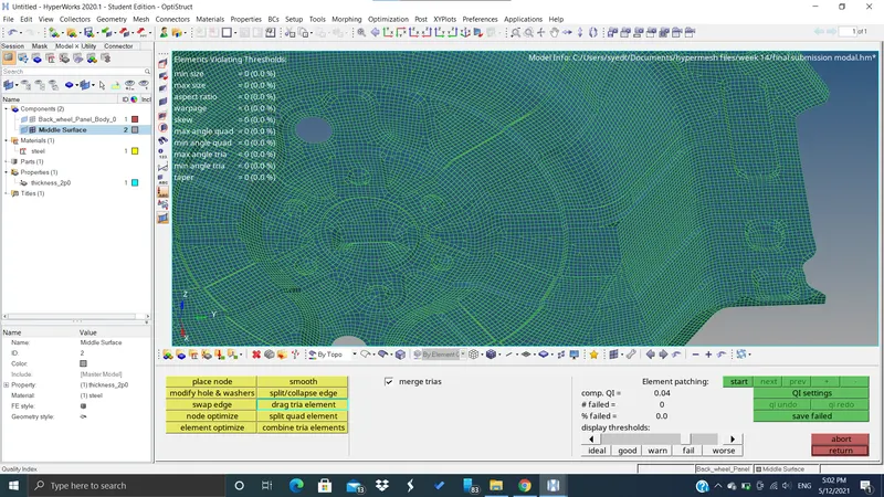
- in this way, we eliminated all the failing elements and then got very good quality mesh and a better flow of mesh with less concentration of trias
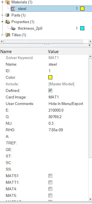
- then after creating the whole mesh we created material and property for the mesh by using create option then material then the property
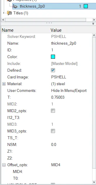
- and in property, we assigned the thickness of the mesh as 0.7503 which was the original thickness of the component
- and then we assigned that property to the mid surface.
Results:-
- So we learnt how to create a better mesh flow by eliminating the trias and failing elements
- we learned how to do a better manual geometry clean up
- we learned how to assign thickness to the mesh according to the parent geometry
- we learned to use different new tools such as project nodes for measuring the thickness, etc
- we understood more about the failure types and their reasons for failure
- we learned what operation or which tool to use for what kind of failure
- such as elements failing for aspect ratio we use re-mesh or place node option to fix them
- elements failing for skewness we can place nodes to increase the angle of the smaller angle side, etc