Project - 2 - Meshing on the suspension Assembly
Objective:-
- To do geometry check.
- To fix all the geometrical errors if present.
- To extract the mid surface of the component which is possible to extract with the same ribs compartments and other components of the geometry.
- To check for unnecessary cons and necessary cons and have a proper connection between two different parts of geometry.
- To do 2-D meshing where ever the thickness is less than 5 mm.
- To fix all the falling elements for minimum length, maximum length, aspect ratio, skewness, warping, jacobian, maximum quad angle, minimum quad angle, minimum tria angle, maximum tria angle.
- To do 3-D meshing, where ever the thickness of the component is greater than 5 mm and the mid-surfacing is not possible.
- To check for kinks and tet collapse and fix all the failing elements.
- To assign thickness to the extracted mid surface by assigning property to each mid surface of different thicknesses.
- To modal, the suspension spring using CBAR elements.
- To create connections where ever whichever type of connections are required.
- At last to use the transform tool to mirror the assembly to the other side by using 3 point mirror by coping the entities.
Introduction:-
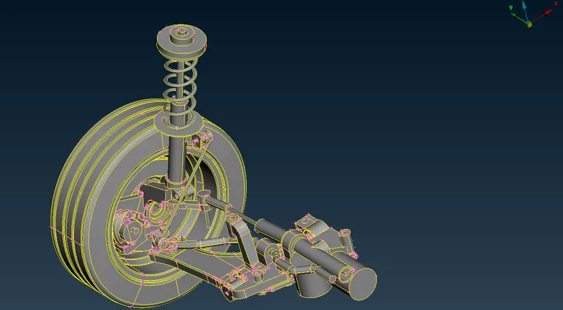
- Received a model of Rear-Wheel assembly of a car the suspension assembly of a car consists of tires, the air in the tires, springs, shock absorbers, struts, arms, bars, linkages, bushings, and joints. The suspension system components are located between the frame of the vehicle and the road. The Rear-Wheel assembly of a car undergoes a huge amount of stress for which it is very important to modal the suspension assembly very precisely so that it doesn't go under any kind of failure.
- For this project, I received half part of the Rear-Wheel assembly of a car which at the end we can mirror to the other side using the appropriate tool because it is a symmetric assembly.
- To modal this assembly, I used 2-D elements for meshing the tire, rim and other components whose thickness is less than 5 mm and mid-surface extraction is possible.
- And then used Solid meshing for the complex components which have thicknesses of more than 5 mm
- And used CBar elements from the NASTRAN deck to model the suspension spring.
- Then assigned thickness to all the mid surfaces and switched to show shells as solid
- Then fixed all the failing elements.
- And at last, used the Transform tool to copy and mirror the whole assembly to the other half.
MODAL RECEIVED 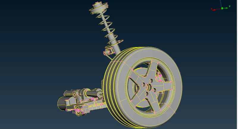
Theory:-
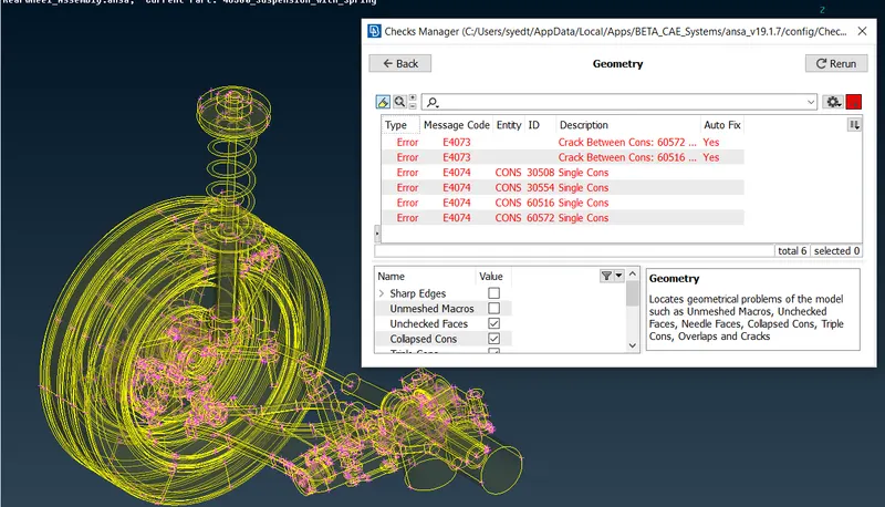
- After importing the model into ANSA v 19.1.7, firstly did the geometry check by using the checks tool
- Tools--> Checks--> geometry
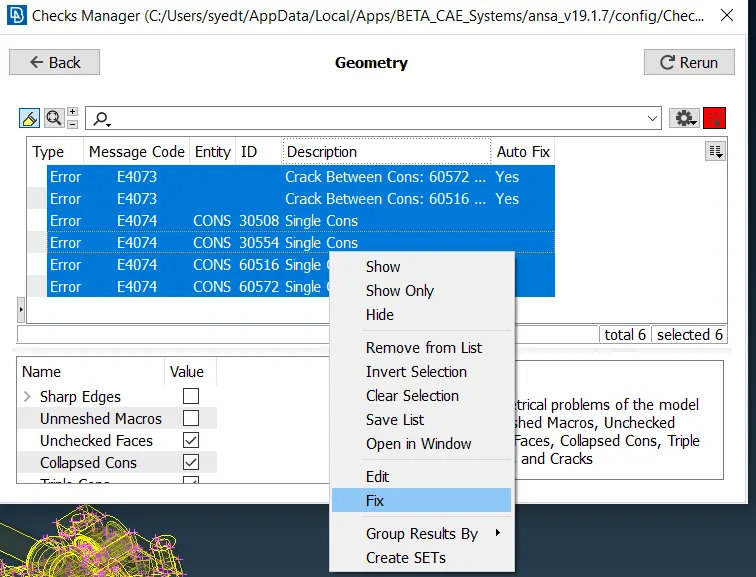
- Where many single cons and unchecked faces appeared as errors
- Which I fixed using the fix tool
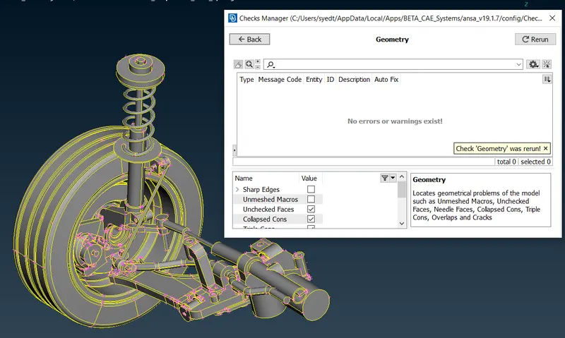
- After fixing all the geometrical errors, used the orient tool to fix all the orientation issues if there was present any
- Then after carefully observing the assembly found that it has many components which need different approaches to mesh
- So for that, I started with the wheel and rim part
- So for that, I isolated the Wheel first by using the iNot tool and locked that wheel component in a different locker using the Lock tool
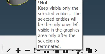
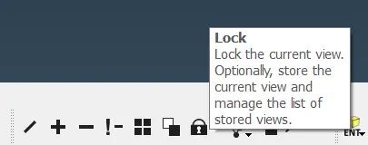
after isolating the wheel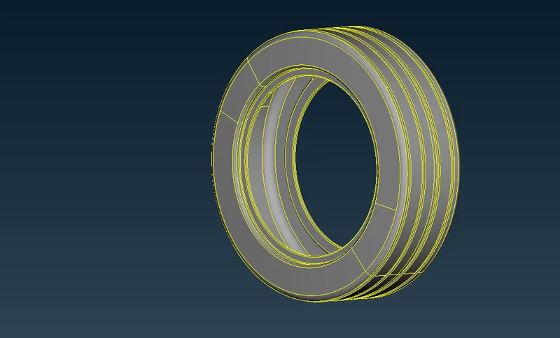
- After isolating the wheel, I looked for the geometrical errors in the wheel
- Then after that, by using the offset tool extracted the mid surface of the wheel
- faces--> offset
- Then selected the faces and typed in the offset value which is half of the thickness of the wheel
- After getting the whole mid-surface used the orient tool to fix all the geometrical errors followed by a geometry check again.
- Then created a new PShell property card for the mid surface by using Lists--> Property--> New--> Shell
- And there assigned the thickness and then applied that property (PID) to the mid surface.
- After that, I meshed the mid surface of the wheel by using the given Quality Criteria.
- And after meshing fixed all the failing elements.
While checking for the geometrical errors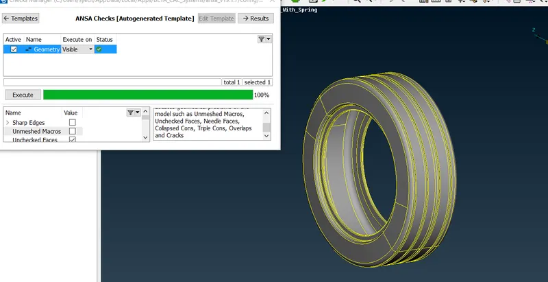
Offsetting using Offset tool from Faces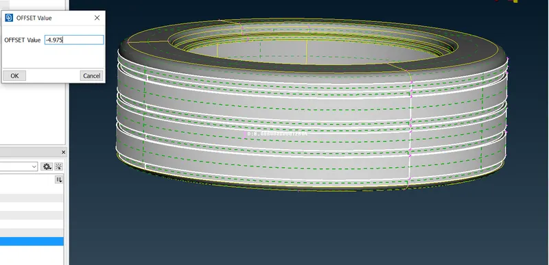
After getting the complete mid-surface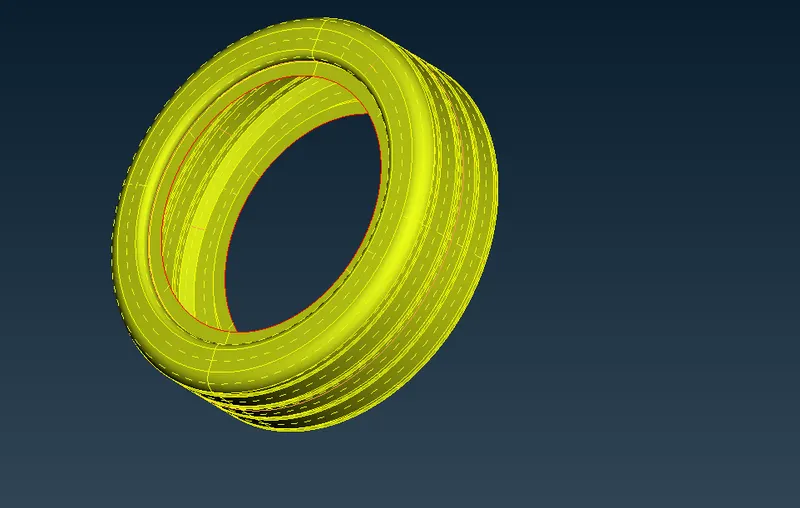
Creating a new property for the mid surface to assign the thickness to the mid-surface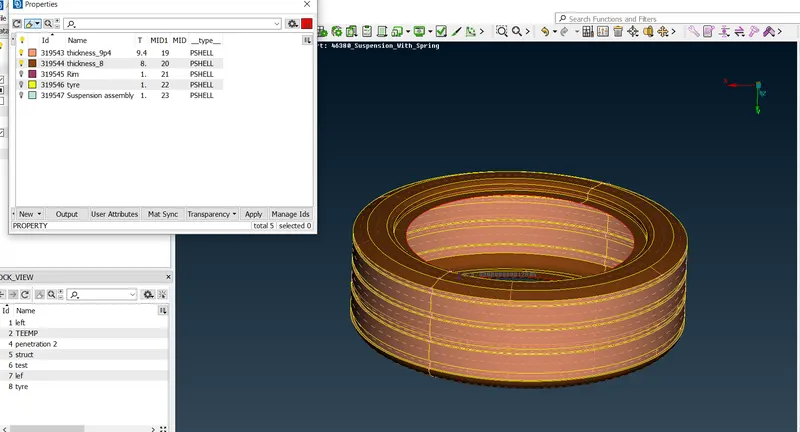
After completely meshing the wheel mid-surface with quads and trias and after fixing all the failing elements for the quality criteria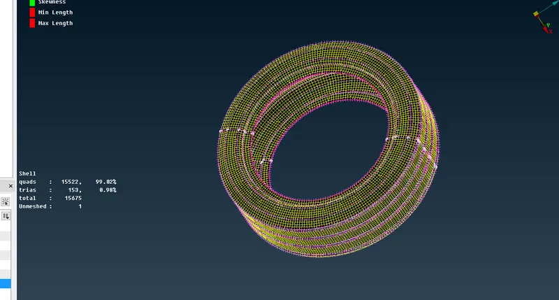
- Similarly, for the rim part, I used the same procedure and quality criteria for meshing it
The rim of the tire after extracting the mid surface by using the Offset method and
after assigning property to each part having different thickness
and after performing a geometry check after extraction of the mid surface
(different colors indicates different PIDs)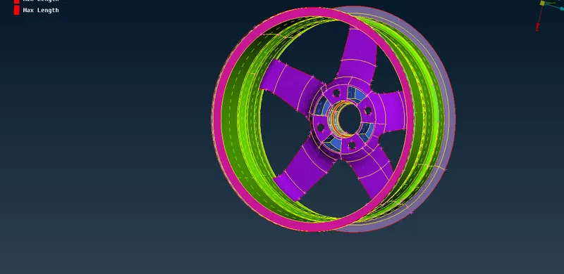
Rim part of the tire after complete meshing and with zero failing elements?
used the same quality criteria as the Wheel part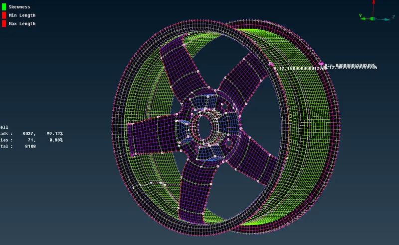
Quality Criteria used for meshing the Tire and Rim part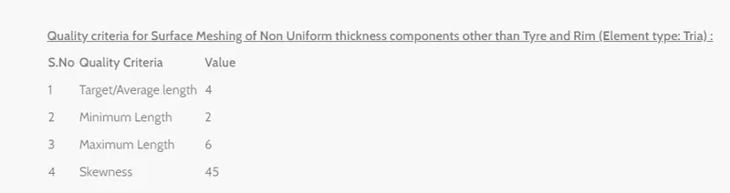
- Similarly, for some other components of the suspension assembly, I used 2-D meshing for modeling
- Which were having a thickness of less than 5mm
- I used the same procedure as the Tire and Rim to mesh them
- Such as I used the Offset tool for extracting the mid surface then the orient tool and then geometry check
- Then created a new property for each part having a different thickness and then assigned that property to that part.
- Then used the given quality criteria values for meshing and fixed all the failing elements after complete meshing for this quality criteria
Quality Criteria used for meshing other parts having a thickness less than 5mm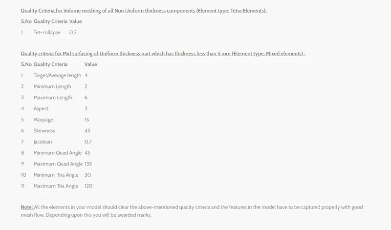
Inner rim part after completely extracting the mid-surface and assigning the property to the parts having different thicknesses
and performing a geometry check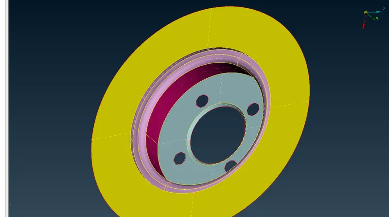
after completely meshing and fixing all the failing elements with zero failing elements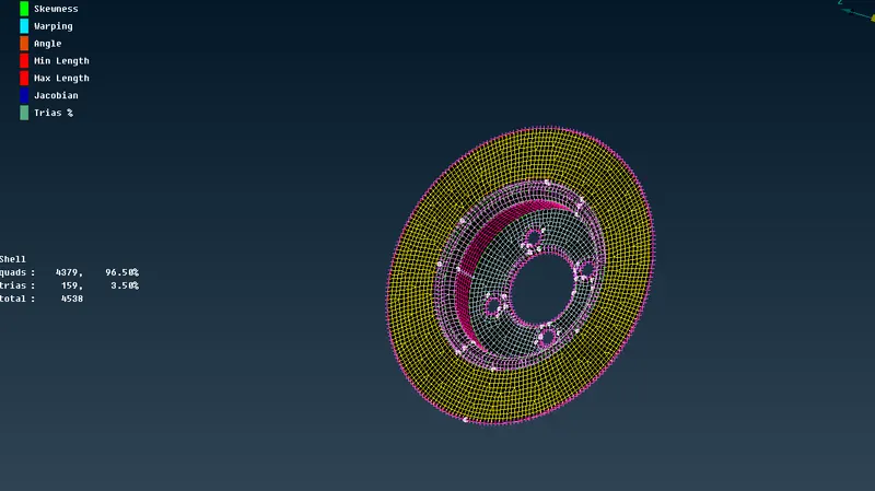
Mid-surface without any geometrical errors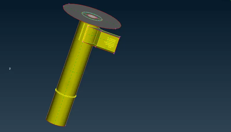
Completely meshed with zero failing elements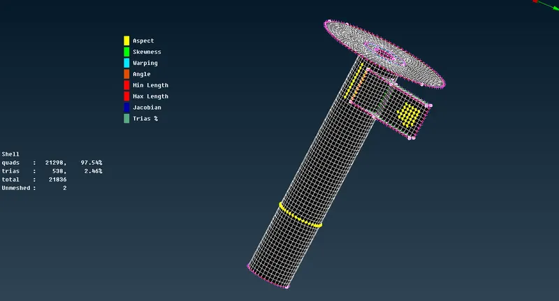
Mid surface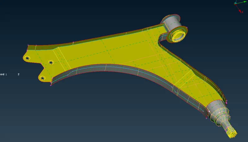
completely meshed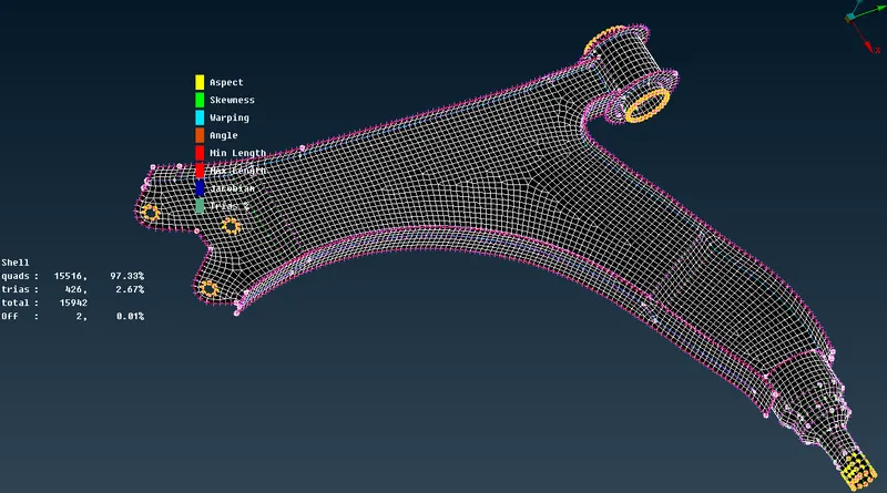
Mid-surface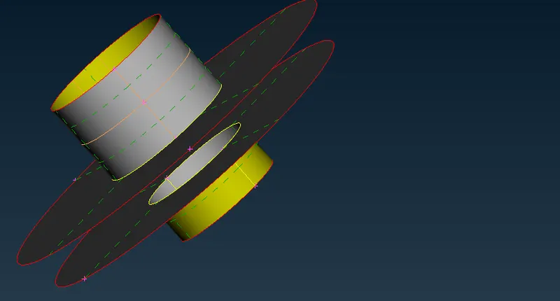
completely meshed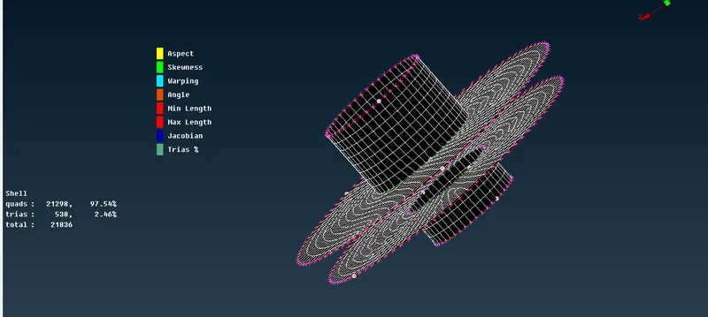
- There were few components on which 2-D meshing wasn't possible
- For which I did 3-D (volume meshing) on them
- Components which were having thicknesses of more than 5mm
- To do that first I created a 2-D tria mesh over those components
- then checked for failing elements for the given quality criteria settings
- Then moved to the Volume mesh deck
- Where first I defined the meshed component by using Volumes--> define--> manual-->auto
- Then selected the tria meshed component and did a middle mouse click
- After this, I created a new PSOLID Id
- Then clicked on Volumes--> List
- And in the list, there was a PSOLID ID that was unmeshed
- Where by doing a right-click on it I remeshed it using TETRA RAPID
- Then after this switched to hidden where I fixed all the failing elements for the tet collapse value
Completely Tria mesh did and fixed all the failing elements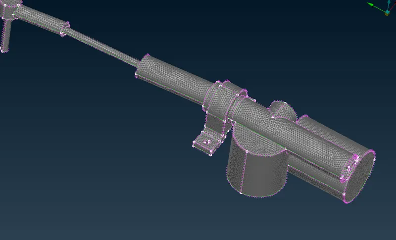
Volume Mesh deck
While using the Define Tool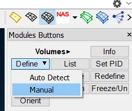
Selected the Define tool--> Manual--> Auto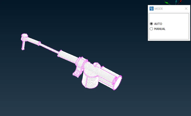
After doing the middle this dialog box appeared where I created a new PSOLID ID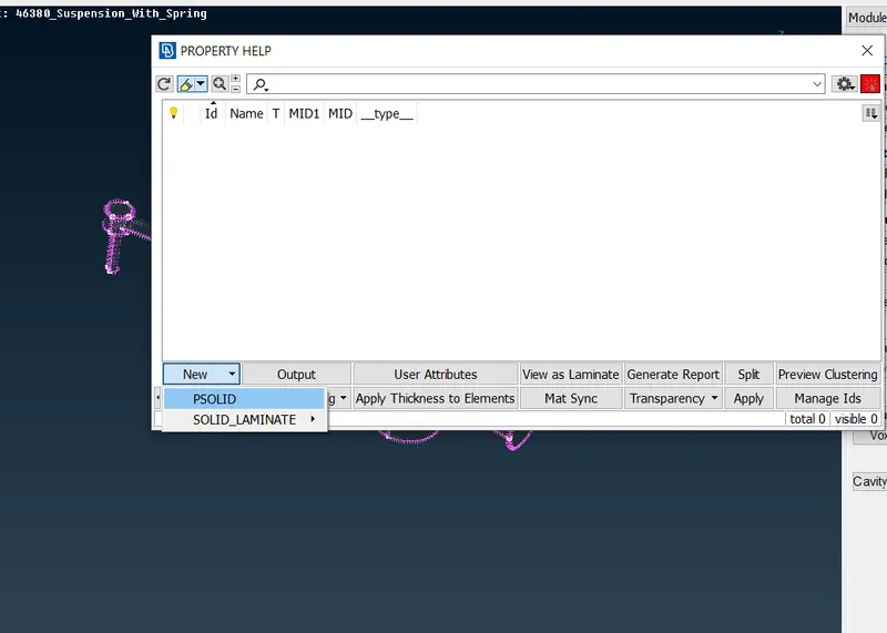
Created a new PDOLID id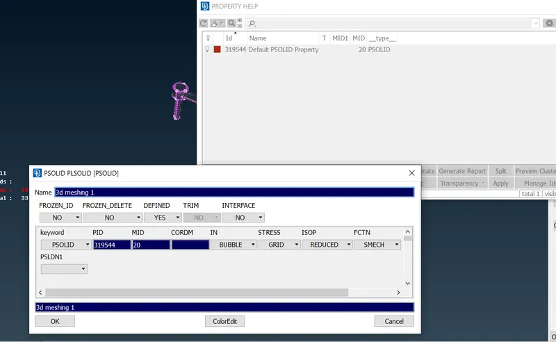
Then by clicking o the List Tool I remeshed the Undefined PSOLID Id using TETRA Rapid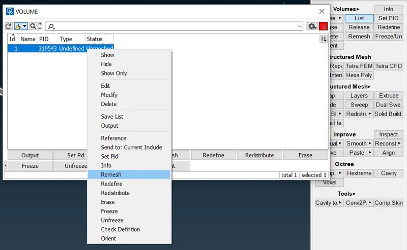
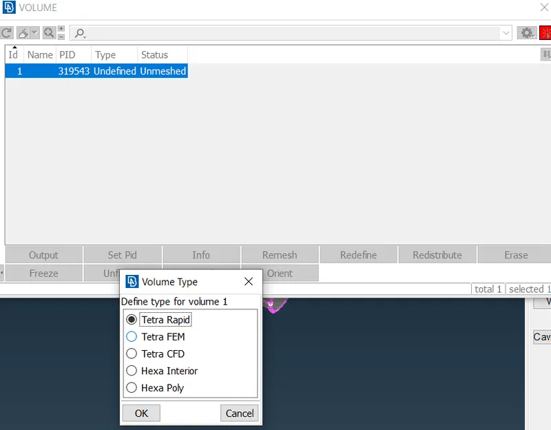
Tetra Mesh done and fixed all the failing elements for yet collapse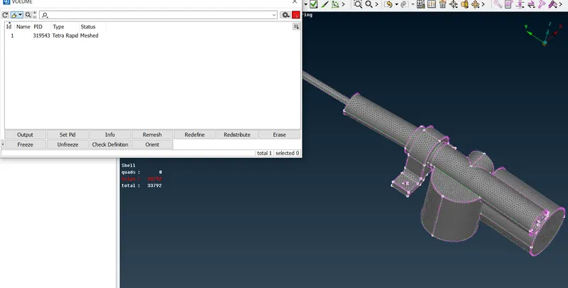
- Similarly followed the same procedure for meshing the other components which are having thicknesses more than 5mm
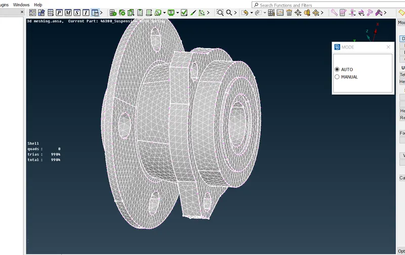
All the Component on which I did Volume meshing with zero failing elements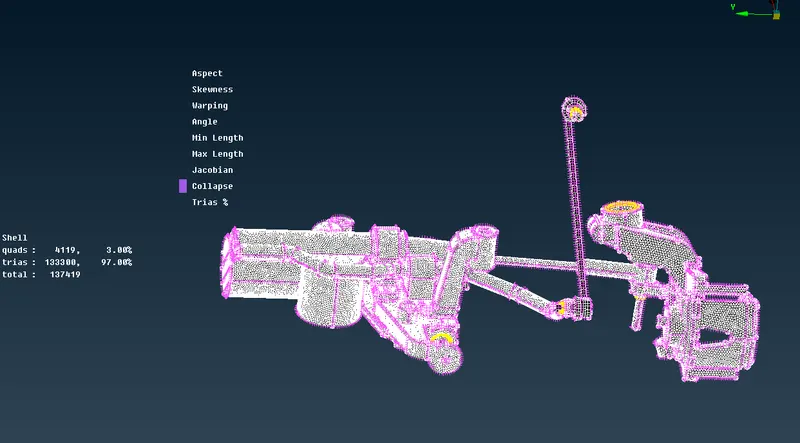
- so after this for the spring suspension part, it was not possible to do a 2d meshing since the mid surfacing was not possible
- and the Hexa meshing is a bit difficult to perform
- so to make the mesh easier, efficient, convenient, and less time consuming
- I used the Cbar element from the NASTRAN deck for modeling the Spring component
- To do that first I created a curve out of the given geometry of the spring
- Since the cross-section area is constant so It won't be a difficult task to create the CBar element for the spring
- So get the Curve I used the Middle tool from Curve
- After selecting one side end line of the spring did a middle mouse button click and then selected all the other side end line
- Then again did a Middle mouse click
- That's how I got the curve at the middle of the spring
- Then by using Connect tool from Curves selected all the curves and did a middle mouse click
- It connected all the curves and made it a single curve
- After this, I created a point at the COG of the curve that to use an orientation definition while using the Cbar element
- Then after this, I switched to the NASTRAN deck where I selected the CBAR tool
- And then Selected the curve and then changed the selection as "curve (box)"
- Then did a middle mouse click then select the 3D point created as the node for orientation
- Then I specified the length as the element length which was 4
- Then after doing a middle mouse click a box appeared where I created a new PBAR id
- And to assign the A value (cross-section area) as per the radius of the Spring
- used shortcut ?+SHIFT then a dialog box appeared where I inserted the radius of the Spring's cross-section
- After this, it automatically took all the values for the PBAR property card
- Then did a middle mouse click
- Then In presentation Parameters turned the Line elements cross-section as: solids
- That's how I modeled the Spring part
The given Model of Spring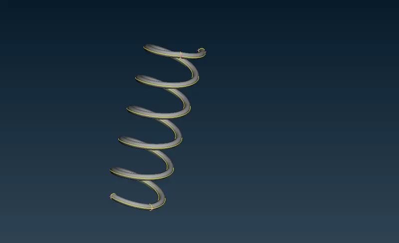
One end of the Cons of the Spring selected after clicking on the Middle tool and then Did a middle mouse click and
then selected the other side cons of the spring and did a middle mouse click so that I got the Curve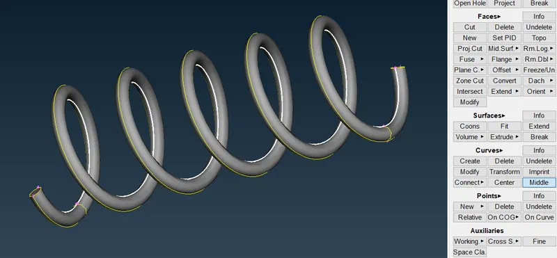
Got the curve and used the connect tool to connect all the curves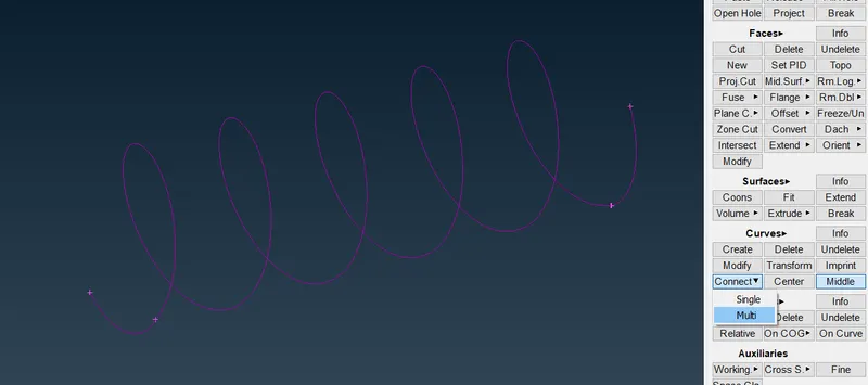
Created a 3-D point using the On COG tool on the curve for the Orientation of the CBAR element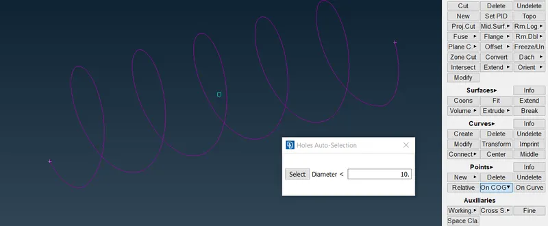
Switched to the NASTRAN deck where I selected the CBAR tool and in the selection box selected curve(box)
And checked the Orientation with node(s)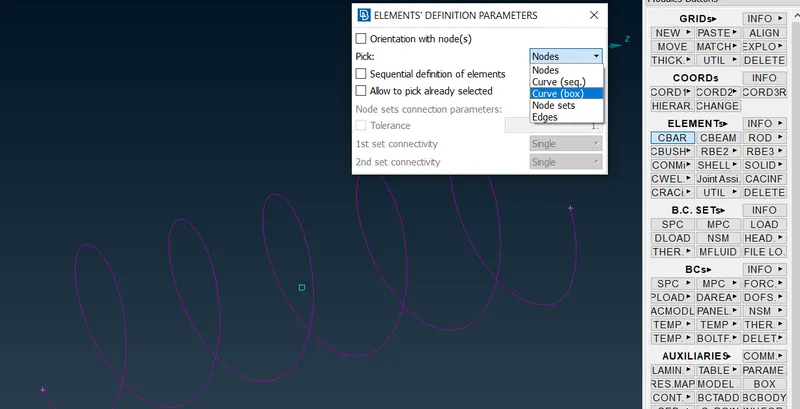
After doing a middle mouse click and I specified the element length as 4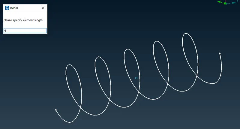
After this a Box appeared where I created a new PBAR property and to assign values I used shortcut ?+Shift
And there I assigned the value of the radius of the Cross-section of the Spring and did a middle mouse click
and everything automatically got assigned
then in the presentation parameters turned the Line Element Cross-section as SOLIDS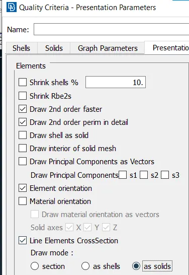
Spring Modeled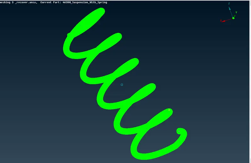
- After this, I did connection by using NASTRAN deck where ever whatever kind of connections was required
- such as seam weld, bolt connections, etc.
bolts connection at pins using rigid elements (RBE2)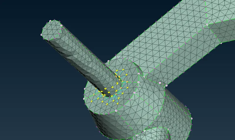
Selecting nodes for creating the bolt connection in the Rim part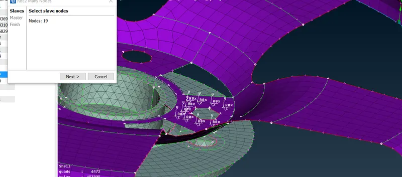
Bolt connection in the Rim part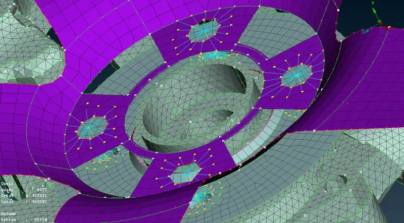
converting the curve extracted by using FE2Curve tool into seamline using Convert tool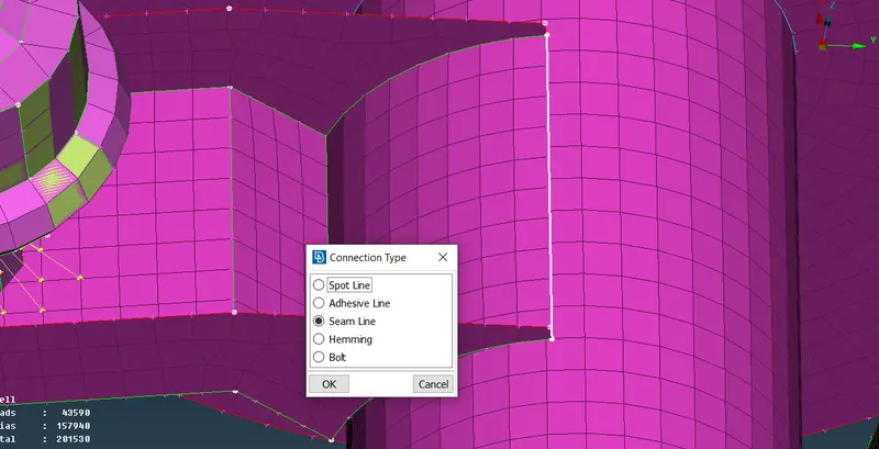
Seam Weld Realised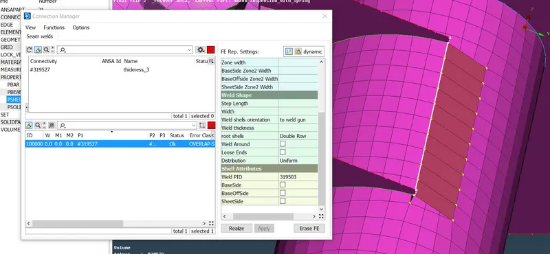
Created Seam weld using RBE2 elements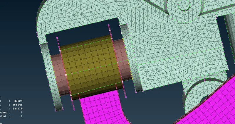
- After this, I used the Transform tool and copied the entities, and used Symmetry by Mirror 3-point plane
- and reflected the whole assembly after coping to the other side which created the whole assembly
Transform Tool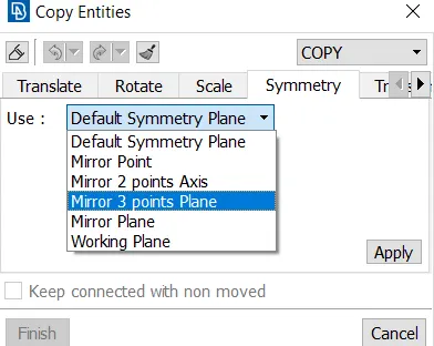
Using Mirror 3-Point plane tool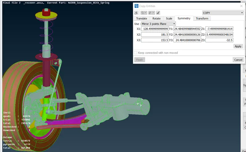
Final modal after complete modeling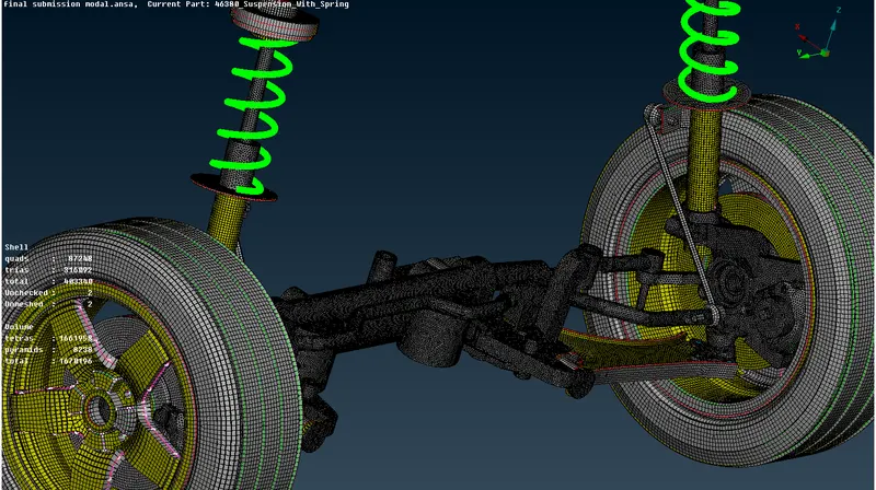
Conclusions:-
- Learned how to model huge geometries with all necessary tools such as 2-D meshing, 3-D meshing, 1-D meshing, making connections, switching to shell as solids, and line element cross-section as solid
- Learned how to approach meshing for a component
- learned which kind of mesh is feasible for which kind of geometry
- Learned how to make proper connections in the Rear Wheel Assembly
- Learned how to use different options in Transform Tool and do a perfect symmetric reflect
- Learned the complexities of geometry and how to extract exact a mid surface perfectly
- Learned about the different parts of Rear Wheel Assembly
- Had a great experience like an industry project
- Learned how to complete a project within a very little time