MBD Simulation on IC Engine Valve Train
Objective:-
- To design and model the IC Engine Valve Train.
- To provide 1500 rpm constant rotatory motion to the Cam.
- To run the simulation of the model after properly assembling it.
- To Calculate the distance between the center circles of Cam while designing, as per the given cam lift(by using Cam loft formula.
- Use Cast Carbon Steel as material for all the parts.
- Calculate the linear displacement, the contact force between
- Cam and Push Rod
- Push Rod and Rocker arm
- Rocker arm and Valve
- And Plot graphs
- Do the same calculation and plot graphs for two different Cam lifts.
- Conclude Results.
Introduction:-
- The IC engine Valve train is made up of five parts such as
- Cam
- Rocker Arm
- Push Rod
- Valve
- Valve mount
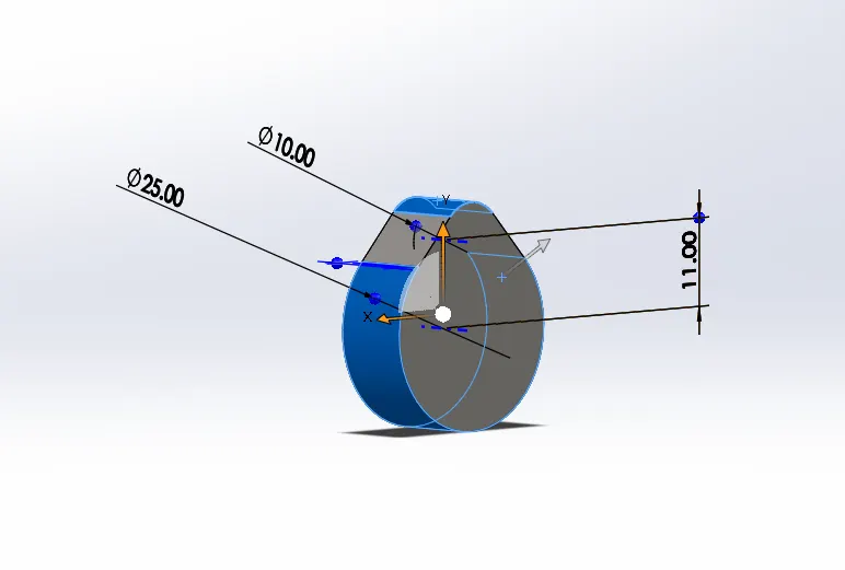
- Design of Cam with 3.5mm cam lift:-
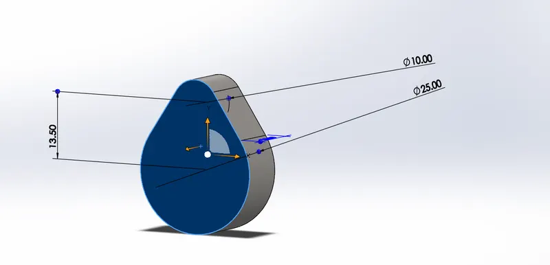
- Design of Cam with 6mm cam lift:-
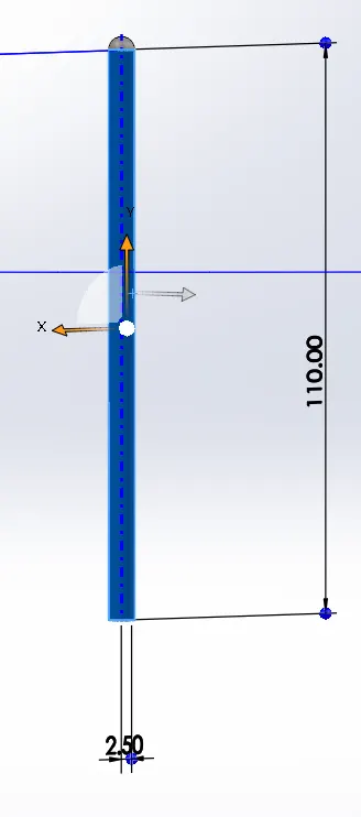
- Design of Push Rod:-
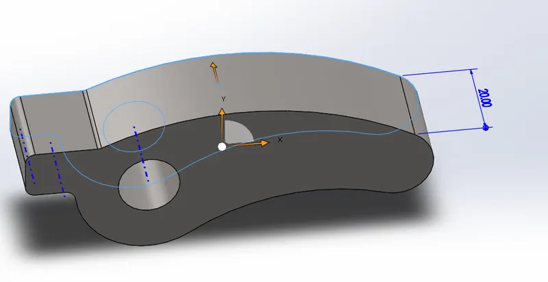
- Design of Rocker Arm:-
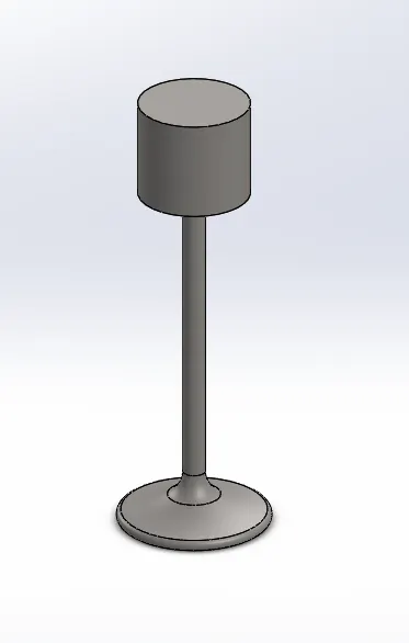
- Design of Valve:-
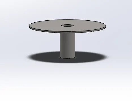
- Design of Valve mount:-
Theory:-
- In this model when we provide power to the Cam then because of the transfer of power the valve starts to have a reciprocating motion.
- First, we calculated the cam lift by using the Cam lift formula given in the challenge
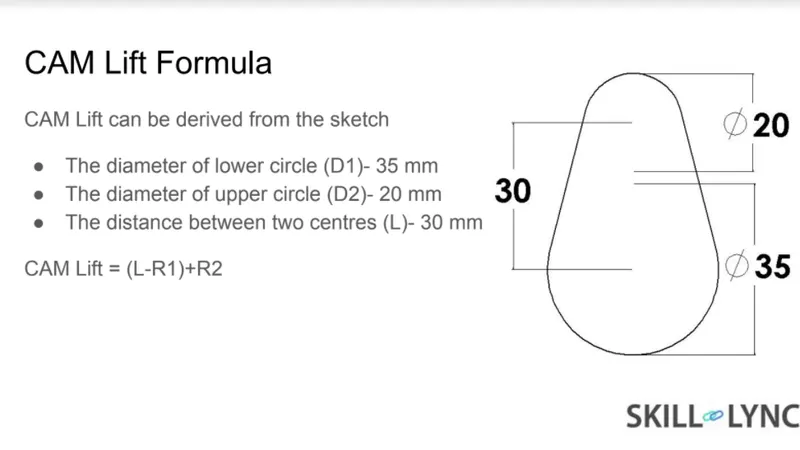
- By using this formula we calculated the distance between the two circles of the cam, as the cam lift is already given in the challenge
- For Cam lift = 3.5mm
- since R1= 12.5mm
- R2= 5mm
- So L= 3.5+ 12.5-5
- L= 11mm
- For Cam lift = 3.5mm
-
- For Cam lift = 6mm
- R1= 12.5mm
- R2= 5mm
- So L= 6+12.5-5
- L= 13.5mm
- For Cam lift = 6mm
- Then we assembled the model after designing it properly by providing the required constraints.
- After assembling the model we moved to SolidWorks motions
- then there we first provided clockwise constant rotation to the Cam.
- Then we added a spring between the face of the valve mount and the valve of 10N/mm2 and 45mm length.
- Then we changed the material of the components to cast carbon steel.
- Then we did the motion analysis.
Results:-
- Case1:- For the 3.5mm Cam lift
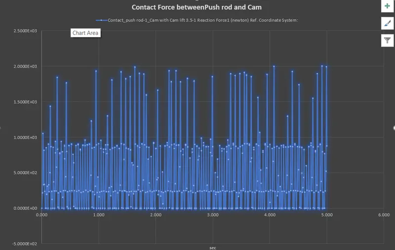
- The contact force between the cam and push rod:-
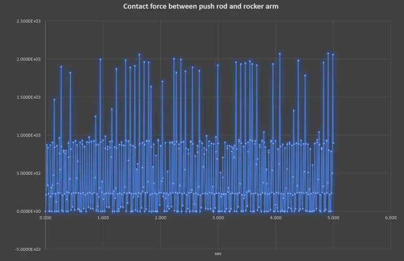
- The contact force between the pushrod and the rocker arm:-
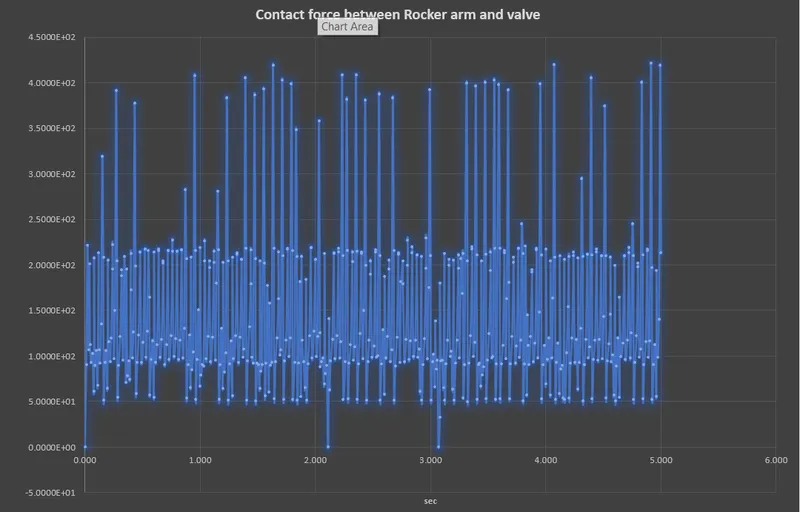
- The contact force between Rocker arm and the valve:-
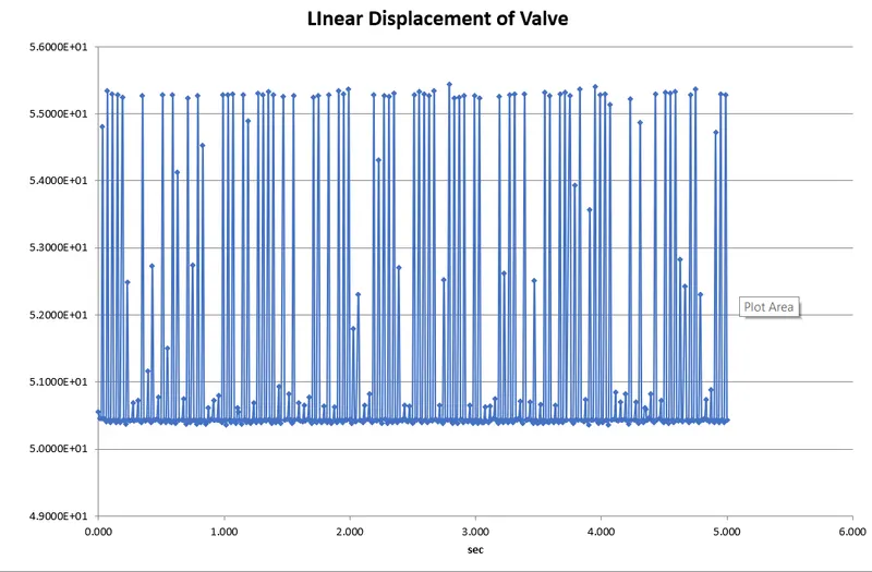
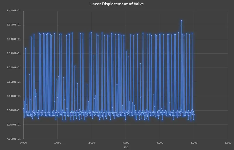
- The linear displacement of the valve:-
- Case 2:- For 6mm cam lift:-
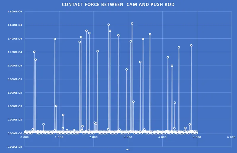
- The contact force between the cam and push rod:-
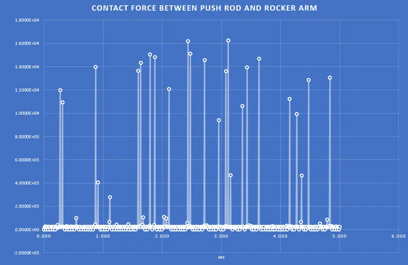
- The contact force between the pushrod and the rocker arm:-
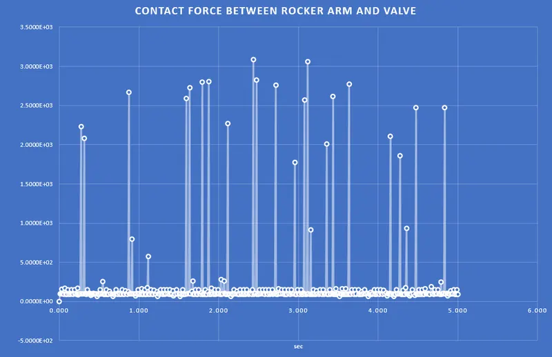
- The contact force between Rocker arm and the valve:-
- The linear displacement of the valve:-