Project 1 - 2D meshing on the instrumental Panel
Objective:-
- to check for geometrical errors and fix them
- create a mid surface of the given model using appropriate tools
- create surface connection in the mid surface between ribs, dog houses, and parent surface to have a proper mid surface.
- create a 2-D mesh over the mid surface
- assign thickness to the extracted mid surface
- assign criteria parameter values
- check for the failing elements
- fix all the failing elements using required tools for the different kinds of failures
Introduction:-
- For this project, received a half part of the model of a dashboard of the car
- which is very complex in structure and has a variable thickness
- it consists of a lot of ribs, dog houses, and other sections on it
- The dashboard of a car is a plastic component that holds a lot of devices such as a speedometer, music system, A.C holes, and sections, storage compartments, etc. It is also called an Instrument Panel, It is a control panel set within the central console of a vehicle or small aircraft. Usually located directly ahead of the driver, it displays instrumentation and controls for the vehicle's operation.
- So that's why it consists of that many ribs just strengthen it.
Model Recieved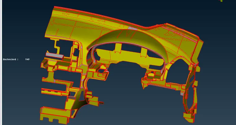
Theory:-
- First imported the given model into ANSA
- then by observing carefully found that there is a lot of single cons
- so to fix that used the toppo tool
- then after that, I used the orient tool to fix all the orientation issues
After fixing all the geometrical issues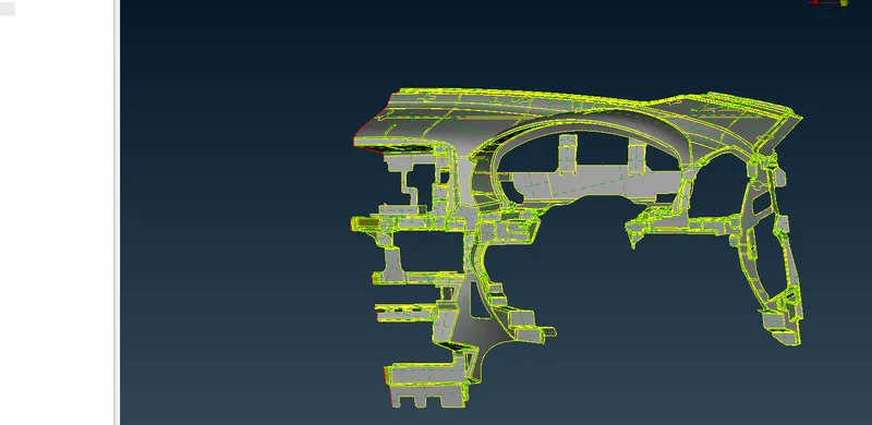 I
I - after fixing all the geometrical issues
- Inspected the given Geometry very carefully and then by using the measure tool
- Measured the thicknesses at several different positions to know that whether the geometry is of uniform thickness or not
- then after checking the thickness at the different positions it came out that the geometry is of non-uniform thickness
thicknesses measured at different positions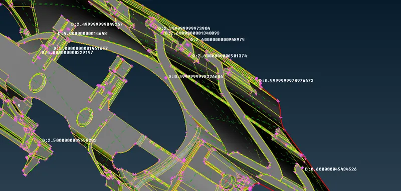
- after measuring the thickness it came out that the base surface is 0.66 mm thickness
- So first I extracted the mid surface of the base surface by using the offset tool
- Faces--> Offset
- After selecting one side of the face of the base surface did a middle mouse click
- then inserted an offset value of 0.3 which is the half of the value of its thickness
- Then did a middle mouse click which resulted in the mid surface of the base surface of the IP console
- Then after getting the mid-surface first assigned the thickness to the mid-surface
- By creating the property Id by using the Lists--> Property--> New--> PSHELL
- Then there I assigned the thickness of the mid surface by inserting the value of the thickness as 0.6
- Then Applied that property card to the base mid-surface
using the Offset Tool to extract the mid-surface of the base surface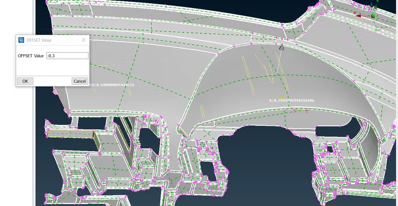
After getting the mid-surface using the checks tool to check for geometrical errors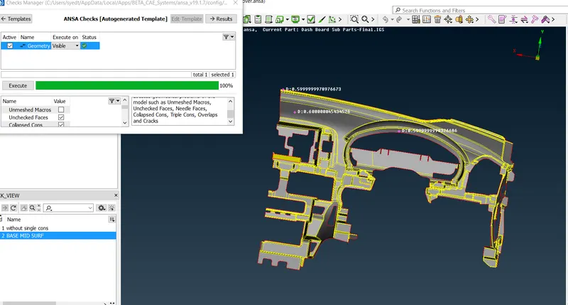
- After getting the base mid-surface extracted the mid surface of the ribs and other components of the geometry
- But for every component, the Offset tool is not feasible
- So for the ribs which were similar on both sides, I used Faces--> Middle
- After selecting one side identical face did a middle mouse click and then again selected the other side identical face
- Then it extracted the mid-surface out of it
- And for the ribs which were not identical to both sides or using the Middle tool is not feasible neither the Offset tool
- So in that case I used the Curves--> Middle tool
- Through which I got the curve at the top middle of the top face of the rib
- Then By using the Cons--> project tool I projected that Curve over the Base mid-surface
- After that by using the curve and the con
- Created a new surface using faces--> New--> Fitted or Coons which is the exact mid-surface of the rib.
- Then after that for the solid cylindrical surfaces, I used the CONS2CURVE tool to get the outer curve
- And then by using those curves I created a new surface which is the mid surface the solid cylinder
- And in this way after extracting the mid surface of every component I created a different property card for each having a different thickness.
- And for a component I used the transform tool as both of them are identical so I just used the symmetry tool from Transform to get the mid-surface
Using Transform Tool to get the mid surface of two identical components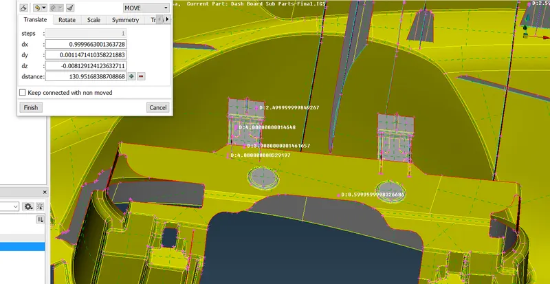
Using The Faces--> Middle tool to get the mid surface of a rib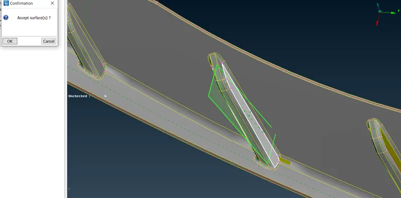
Using the Curve--> Middle to get the Curve between the top two end cons of a rib /
Then projecting that curve to base surface and creating a surface between them gives the mid-surface of the rib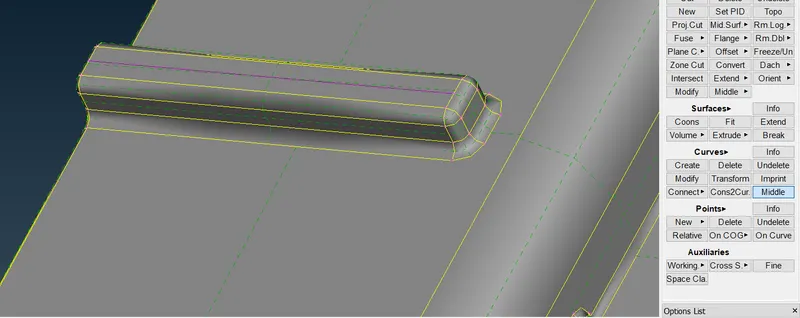
Using CONS2CURVE to get the curve out of the solid cylinder and then by creating new surfaces between them got the mid-surface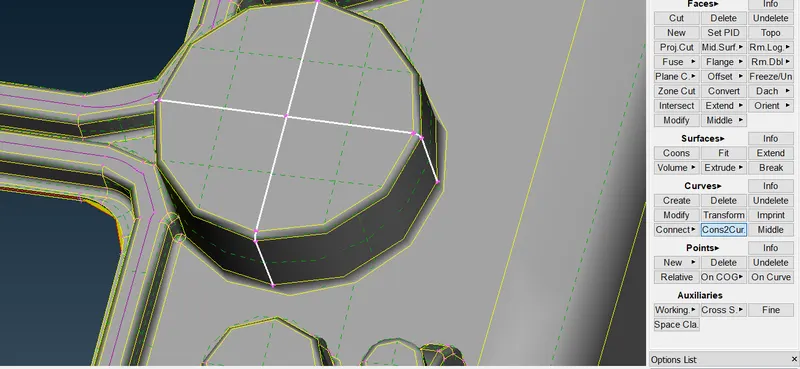
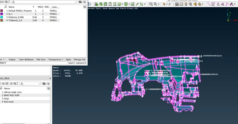 Applying property cards to all the different thickness Components of the Mid surface
 - After getting the accurate and complete mid-surface, moved towards meshing the surface
- And by using the given quality criteria meshed the whole mid surface
- after completely meshing the surface I switched to Hidden mode where all the failing elements were visible then there I fixed all the failing elements
Meshing Quality criteria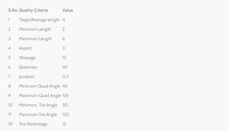
Final Model picture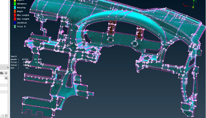
Conclusions:-
- Learned about the complexities of element failures and how to fix them
- Learned about the geometrical complexities
- Learned how to extract mid-surface for a complex geometry