Creation of Column Schedule and Drawing Template using AutoCad
Q1:
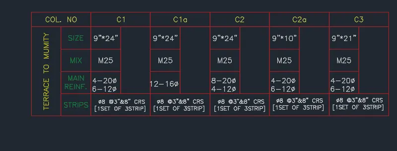
Create a column schedule as shown in the figure.
Note: Create a column schedule with the help of lines. Also, insert text with the help of Dtext command or Single Line text.
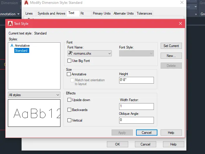
Hint: Use font name: romans.shx; Height: 8”, Justify: Left
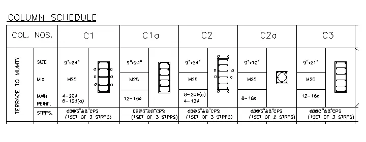
Aim: To create column schedule as shown in the figure using AutoCAD
Procedure:
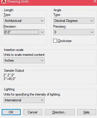
- Type "UNITS" in the command prompt and press enter.
- In the unit tab, select the type as "Architectural" and insertion scale as "inches".
- Click ok.
- Select line command from the ribbon tab.
- Specify the starting point by clicking 0,0 on the workspace.
- Specify the next point by keeping the cursor in the positive Y direction and click 2'0".
- Specify the next point by keeping the cursor in the positive X direction and click 8'0".
- Specify the next point by keeping the cursor in the negative Y direction and click 2'0".
- Specify the next point by keeping the cursor in the negative Y direction and click 8'0".
- Press "esc".
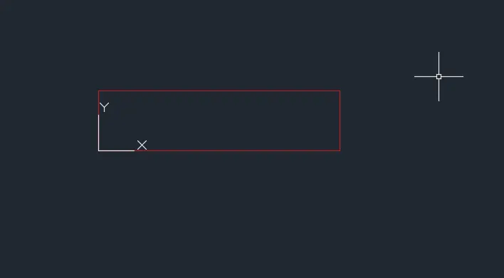
- Select the previously created object in the workspace.
- Type "COPY" in the Command prompt and press enter.
- Select the left bottom corner point as base point and press enter.
- Move the copied object along the base point in X plane.
- Keep the cursor on right bottom point and click.
- Repeat the same procedure another5 times to create upper row.
- Now press "esc".
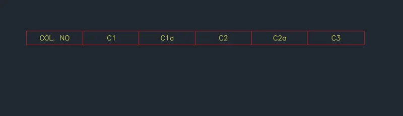
- Type "dimstyle" in the command prompt and press enter.
- From the ribbon tab, select "Annotate".
- Under text, select "manage text styles".
- Specify the text height as 8" and font as "roman.shx"
- Click ok.
- Select "text" toool from ribbon tab.
- From the drop down list select "single line" text.
- Now the keep the pointer in the 1st (left most) box and click as per the alignment required.
- Type "Column Nos." and press enter.
- Now the keep the pointer in the 2nd box and click as per the alignment required.
- Type "C1" and press enter.
- Now the keep the pointer in the 3rd box and click as per the alignment required.
- Type "C1a" and press enter.
- Now the keep the pointer in the 4th box and click as per the alignment required.
- Type "C2" and press enter.
- Now the keep the pointer in the 5th box and click as per the alignment required.
- Type "C2a" and press enter.
- Now the keep the pointer in the 6th box and click as per the alignment required.
- Type "C3" and press enter.
- Select line command from the ribbon tab.
- Specify the starting point by clicking 1st left bottom cornor on the workspace.
- Specify the next point by keeping the cursor in the positive Y direction and click 12'.
- Specify the next point by keeping the cursor in the positive X direction and click 4'.
- Specify the next point by keeping the cursor in the negative Y direction and click 12'.
- Specify the next point by keeping the cursor in the negative Y direction and click 4'.
- Press "esc".
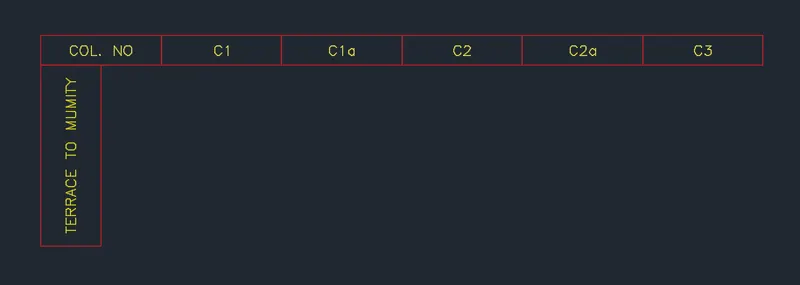
- Select "text" toool from ribbon tab.
- From the drop down list select "single line" text.
- Specify themiddlepoint ofthe text.
- Specify the rotation angle of text is 90.
- Type "Terrace To Mumity" and press enter.
- Select the previously created object in the workspace.
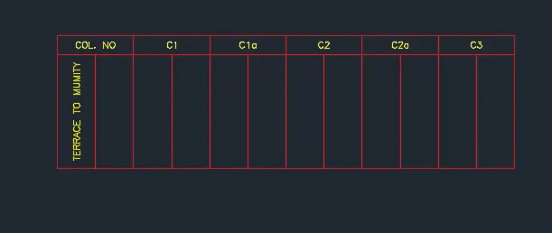
- Type "COPY" in the Command prompt and press enter.
- Copy the newly created rectangle of length 4' and width 12'.
- Select the left bottom corner point as base point and press enter at its right bottom cornor point.
- Continue the steps 10 more times.
- Press "esc".
- Select the previously created object in the workspace.
- Type "LINE" in the Command prompt and press enter.
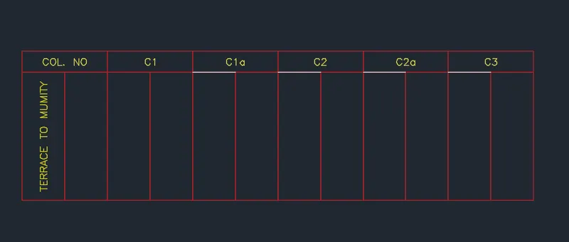
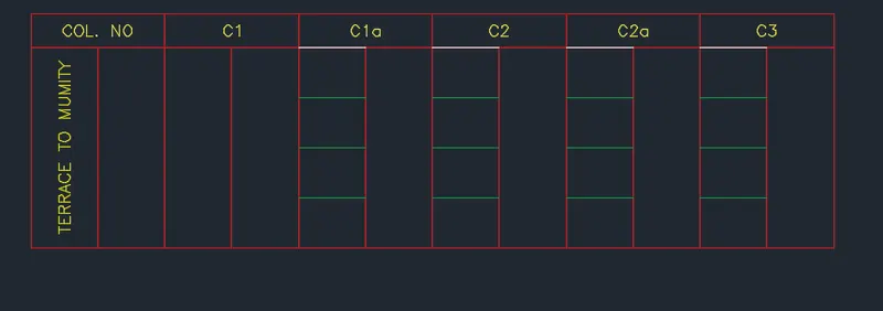
- Draw lines for the offset drawing on 5th,7th,9th,11th column.
- Type "OFFSET" in the Command prompt and press enter.
- creat offset of 3' from the drawing line of the section 5th,7th,9th,11th column.
- Press "esc".
- Select the previously created object in the workspace.
- Type "EXTEND" in the Command prompt and press enter.
- Select the last offset that is created at the bottom person.
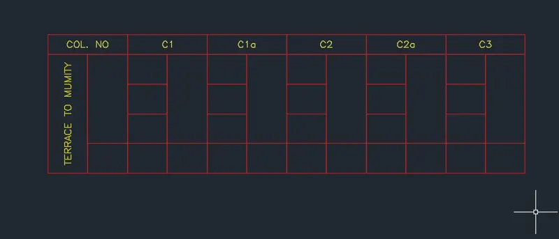
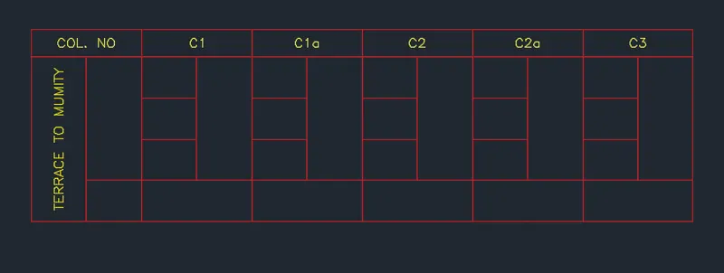
- Type "TRIM" in the Command prompt and press enter.
- Trim the unwanted drawing.
- Now press "esc".
- Select "text" toool from ribbon tab.
- From the drop down list select "single line" text.
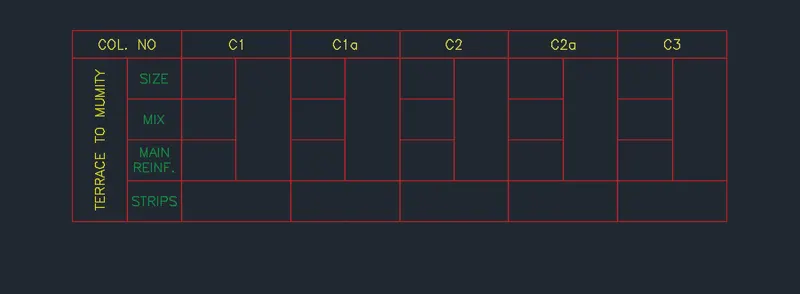
- Now the keep the pointer in the right box of "COL NOS" column and click as per the alignment required.
- Type "Size" and press enter.
- Now the keep the pointer in the right box of "COL NOS" column and click as per the alignment required.
- Type "MIX" and right click.
- Now the keep the pointer in the right box of "COL NOS" column and click as per the alignment required.
- Type "MAIN REINF" and right click.
- Now the keep the pointer in the right box of "COL NOS" column and click as per the alignment required.
- Type "STRIPS" and right click.
- Select "text" tool from ribbon tab.
- From the drop down list select "single line" text.
- Now the keep the pointer in the left box of "C1" column and click as per the alignment required.
- Type "9"x24"" and press enter.
- Now the keep the pointer in the left box of "C1" column and click as per the alignment required.
- Type "M25" and right click.
- From the drop down list select "Multi line" text.
- Now the keep the pointer in the left box of "C1" column and click as per the alignment required.
- Type "4-20#" press enter, type "6-12#" and right click for symbol.
- Press enter for close the command.
- Now the keep the pointer in the left box of "C1" column and click as per the alignment required.
- Type "#8@3"&8"CRS press enter, type [1 SET OF 3STRIP]" .
- Select "text" tool from ribbon tab.
- From the drop down list select "single line" text.
- Now the keep the pointer in the left box of "C1a" column and click as per the alignment required.
- Type "9"x24"" and press enter.
- Now the keep the pointer in the left box of "C1a" column and click as per the alignment required.
- Type "M25" and right click.
- Now the keep the pointer in the left box of "C1a" column and click as per the alignment required.
- From the drop down list select "Multi line" text.
- Type "12 16#" and right click right click for symbol.
- Press enter for close the command.
- Now the keep the pointer in the left box of "C1a" column and click as per the alignment required.
- Type "#8@3"&8"CRS press enter, type [1 SET OF 3STRIP]" .
- Select "text" tool from ribbon tab.
- Now the keep the pointer in the left box of "C2" column and click as per the alignment required.
- Type "9"x24"" and press enter.
- Now the keep the pointer in the left box of "C2" column and click as per the alignment required.
- Type "M25" and right click.
- Now the keep the pointer in the left box of "C2" column and click as per the alignment required.
- From the drop down list select "Multi line" text.
- Type "8-20#", press enter type "4-12#" and right click for symbol.
- Press enter for close the command.
- Now the keep the pointer in the left box of "C2" column and click as per the alignment required.
- Type "#8@3"&8"CRS press enter, type [1 SET OF 3STRIP]" .
- Select "text" tool from ribbon tab.
- From the drop down list select "single line" text.
- Now the keep the pointer in the left box of "C2a" column and click as per the alignment required.
- Type "9"x10" and press enter.
- Now the keep the pointer in the left box of "C2a" column and click as per the alignment required.
- Type "M25" and right click.
- Now the keep the pointer in the left box of "C2a" column and click as per the alignment required.
- From the drop down list select "Multi line" text.
- Type "4-20#", press enter type "6-12#" right click for symbol.
- Press enter for close the command.
- Now the keep the pointer in the left box of "C2a" column and click as per the alignment required.
- Type "#8@3"&8"CRS press enter, type [1 SET OF 3STRIP]" .
- Select "text" tool from ribbon tab.
- From the drop down list select "single line" text.
- Now the keep the pointer in the left box of "C3" column and click as per the alignment required.
- Type "9"x21" and press enter.
- Now the keep the pointer in the left box of "C3" column and click as per the alignment required.
- Type "M25" and right click.
- Now the keep the pointer in the left box of "C3" column and click as per the alignment required.
- From the drop down list select "Multi line" text.
- Type "4-20#" "6-12#"and right click for symbol.
- Press enter for close the command.
- Now the keep the pointer in the left box of "C3" column and click as per the alignment required.
- Type "#8@3"&8"CRS press enter, type [1 SET OF 3STRIP]" .
1.Drawing the column section C1
- Column of size 9"x24" having 20mm dia reinforcement at 4 corners and 12mm dia 6 reinforcement bars in between connected by 8mm dia stirrup.
- Draw a rectangle of size 9"x24" command REC
- specify a point
- click on dimension in the command box - then enter the first value as 9" and second dimension as 24".
- Draw the column outline after a cover of 40mm i.e 0.5" by offset command .
- command "O" - select the object - give offset distance as 0.5".
- Explode the inner rectangle so that the line can be selected separately . command "EXPLODE" - select the inner rectangle - enter

DRAWING REINFORCEMENT:
- By circle draw the reinforcement command "C". Click on Tan Tan Radius on the command box
- Select the left line as one of tangent
- Top line as another tangent
- Give radius as 10mm i.e 0.4"
- Using mirror command create the reinforcement on bottom of the left side of column. Command "MI"
- Select the object
- Give the mirror plane as the midpoint of the 2' line by object snap.
- midpoint on and click on "NO" for erase source object

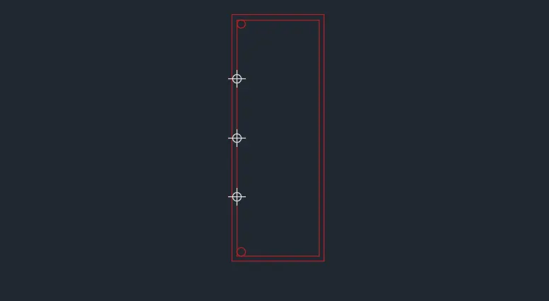
- Divide the line containing the reinforcement by command "DIV"
- Select the object (line) no. of segments to be divided is given as 4 , the line will be divided
- To make the point of division visible, type command "DDPTYPE" in command box
- A dialogue box appears and select the suitable point type appl
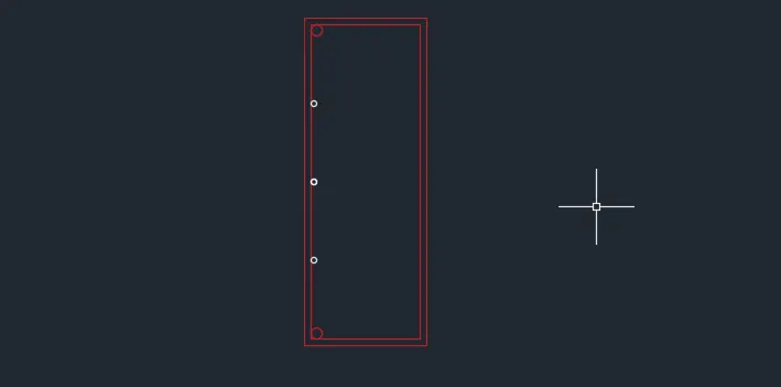
- For the reinforcement of 12mm dia, 6bars
- Create circle by command "C"
- Specify the centre point
- Enter the radius as 6mm i.e 0.2"
- copy the circle command "CO"
- Select the base point as top point on the circle and place it in the centre point of the point created by object snap on
- Place 3 circles as such on each divided point , then delete the point created
- Create similar circles on the other side , right side of the column. For that,
- Mirror the circles Command "MI"
- Select all the 5 circles
- Create the mirror plane from the middle of the 9" line, erase source object
- Give it as "NO" then the mirror image will be created
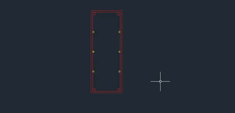
DRAWING STIRRUPS:
- Connect the reinforcement of radius 6mm, 1st row from the top, 2nd row top and bottom and 3 row from bottom.
- Connect the lines as top tangent of the two circles
- Draw the rings by arc - 3 point method, and mirroring it.
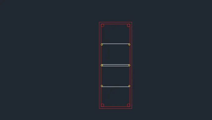
- Fillet the corners of the column outline with fillet radius as 0.5"
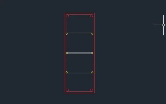
- Use donut command to fill the circle
- command DO
- Specify the inner dia as 0 and outer diameter as 0.8" for 4 corner reinforcement and 0.4" for inside reinforcement
- Specify centre of the donut, it gets filled. Mark "a" for in between reinforcement to indicate it as 12mm diameter.
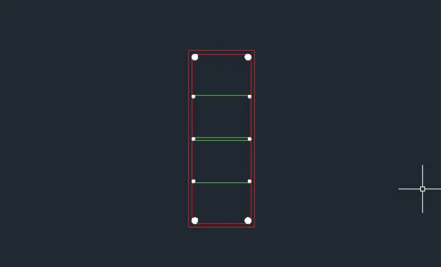
2. Drawing column section C1a
- Column of size 9"x24" having 16mm dia 12bars connected by 8mm dia stirrup.
- Draw a rectangle of size 9"x24" - command "REC"
- specify a point
- click on dimension in the command box
- Then enter the first value as 9" and second dimension as 24"
- Draw the column outline after a cover of 40mm i.e 0.5" by offset command Command "O"
- select the object
- Give offset distance as 0.5"
- Explode the inside rectangle so that the line can be selected separately. command "EXPLODE"
- Select the inner rectangle - enter.

Drawing reinforcement :
- By circle draw the reinforcement command "C"
- Click on tan tan radius on the command box
- Select the left line as one of tangent
- Top line as another tangent
- Give radius as 8mm i.e 0.3"
- Using mirror command create the reinforcement on bottom of the left side of column . Command "MI"
- Select the object
- Give the mirror plane as the midpoint of the 2' line by object snap-midpoint on
- Select erase source object as "NO"-
- Outline the line containing the reinforcement by command "DIV"
- Select the object (line)
- No. of segments to be divided is given as 5, the line will be divided
- Copy the circle (reinforcement) and place it in the centre of the 4 points as here all reinforcement are of same size.
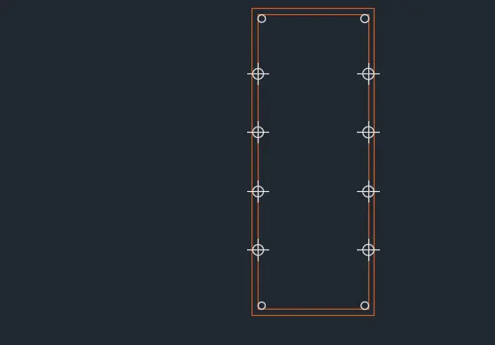
- Mirror the circles to the right side by command "MI" - select all the 6 circles, then draw the mirror plane as the midpoint of the 9" line and give erase source object as "NO"
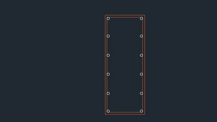
DRAWING STIRRUPS:
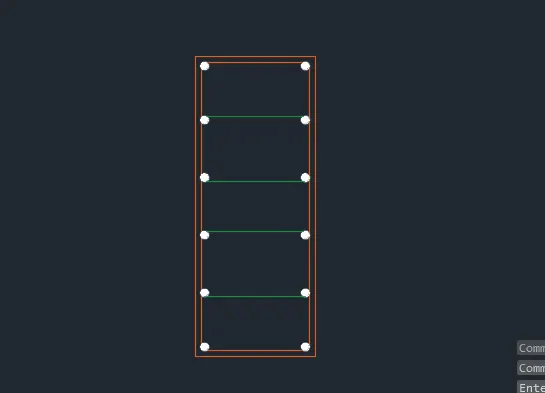
- With line command draw lines in top and bottom of reinforcements to show the stirrups same in the next set also- With arc - 3 point method , draw rings where required
- Fillet the corners with fillet radius of 0.3"
- With "DO" command create donut - give inner diameter as 0 and outer diameter as 0.62"
3. Column C2
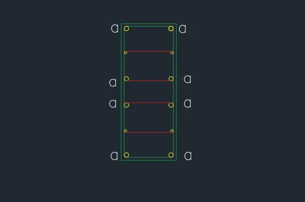
- Column of size 9"x24" having 20mm dia 8 bars shown in figure as "a" and rest 12mm dia 4 bars with 8mm dia stirrups.
Drawing column
- Draw a rectangle of size 9"x24" - command "REC" - specify a point - click on dimension in the command box - then enter the first value as 9" and second dimension as 24"
- Draw the column outline after a cover of 40mm ie 0.5" by offset command Command "O"
- Select the object
- Give offset distance as 0.5"
- Explode the inside rectangle so that the line can be selected seperately.
- Command "EXPLODE" - select the inner rectangle- enter.
DRAWING REINFORCEMENT:
- With circle draw 20mm reinforcement on left corner by tan - tan - radius method radius 0.4"
- Select the circle and create mirror in bottom left corner
- Divide the line by "DIV" command and divide it onto 5 segments 4 points are created.
- Copy the reinforcement to the third and fourth row, Command: "CO"
- Select the circle and place it.
- Mirror the copied circle and the top and bottom circles to right side Command "MI"
- Select the circles
- Then draw the mirror line towards the midpoint.
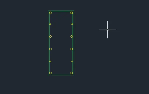
- Create circle of radius 0.23" and place it in centre rest of the points created and mirror it as done in previous step
Drawing stirrups:
- By "L" line command draw lines connecting top and bottom of the reinforcement as in the figure
- Create rings by arc
- Fillet the corners of the column outline with fillet radius 0.4"
- Fill the circle by donut command "DO" - enter inner diameter as 0 and outer diameter as 0.7" and 0.4" respectively
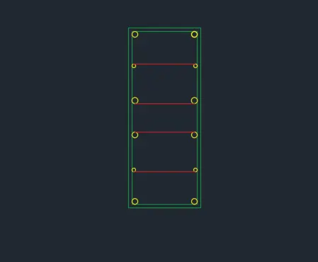
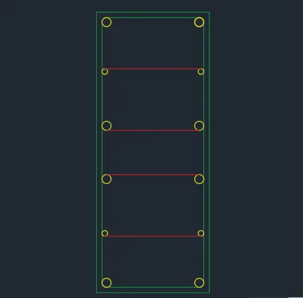
- Mark "a" with single line text on side of 20mm diameter reinforcement for identification.
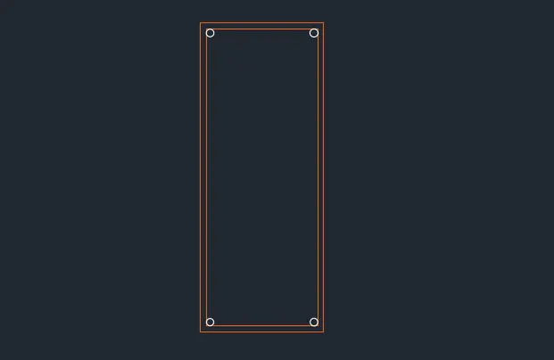
4. Drawing column C2a:-
- Draw rectangle of 9"x10" and give offset of 0.5", explode the offsetted rectangle.

Drawing reinforcement:
- With circle command C - select tan tan radius and select the two corner lines and give radius as 0.3" (8mm)
- Mirror these to the opposite corners
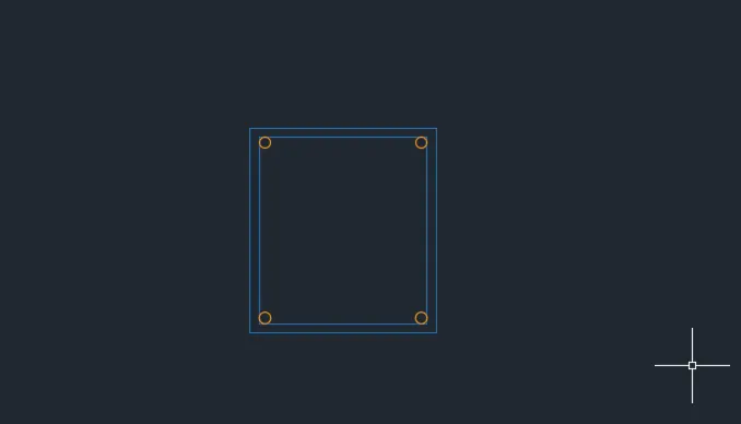
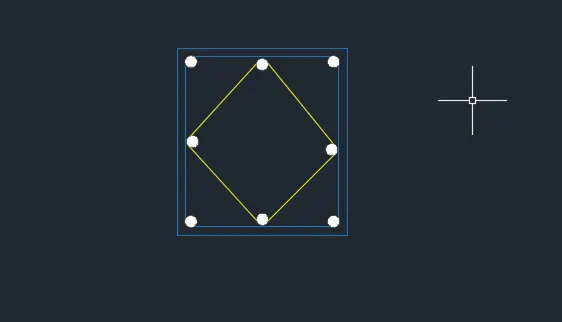
- Draw lines joining the midpoint of the each side , then by circle "C" - tan tan radius - select the two sides as tangent and give 0.3" as radius
- Mirror the circles on opposite side by "MI" command.
- Again draw the other side reinforcement as done above.
- Create rings by arc - 3 point
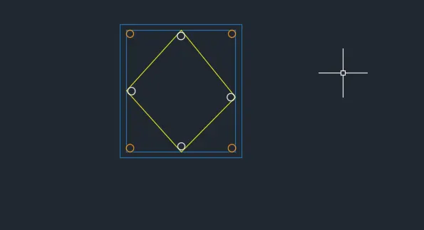
- Fill the reinforcement by donut command "DO"
- Give inner diameter as 0 and outer diameter as 0.6"
5. Drawing column C3
- size 9"x21" reinforcement of 16mm dia 12 nos and stirrups 8mm diameter
Drawing column
- Draw rectangle by command "REC" - click on dimension, give the dimensions as 9" and 21"
- Offset the rectangle with an offset distance of 0.5" by command "O" - distance as 0.5
- Explode the inner rectangle.
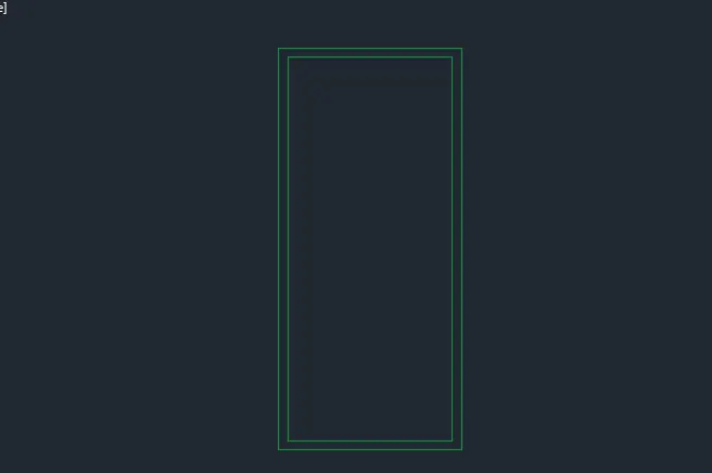
Drawing reinforcement:-
- By circle "C" - tan tan radius
- select the two corner lines and give the radius as 0.3"
- Mirror the circle to the four corners of the column. Command "MI"
- select the circle
- Draw the mirror plane at the midpoint of both the sides.
- Divide the line by "DIV" command into 5 segments , 4 points are created.
- Copy the circle and place it in the midpoint of the points by "CO" command
- Mirror the copied circles on the other side command "MI" - select the object, draw the mirror plane from the midpoint of the 9" line, give erase source as "NO"
- Delete the points.
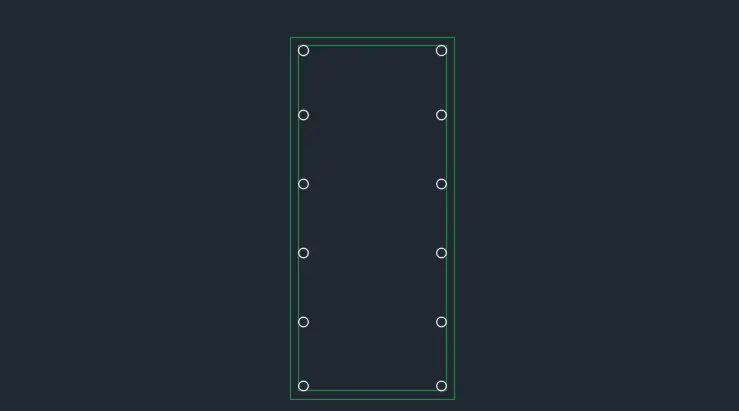
Drawing the stirrups
- With line command "L" draw the line from the top and bottom of the reinforcement.
- Fillet the corners "F" - with fillet radius as 0.3" .
- Create rings with arc - 3 point
- Fill the reinforcement by donut command "DO"
- Give inner dia as 0 and outer dia as 0.6"
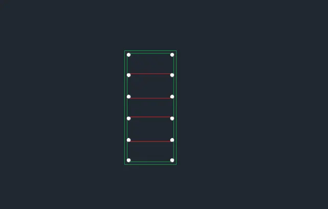
Placing it in column:
- Place each of the drawn columns in the respective table making it a scale of 4"
- Command "SC"
- select the object
- select base point
- scale factor give it as 4".
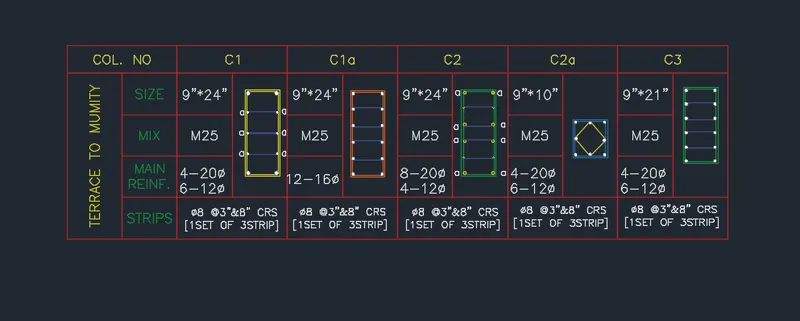
RESULT: The column schedule is draw
Q2:
Create a window schedule as shown in the figures:
Window Schedule:
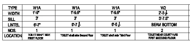
Aim: To create the window schedule as per the given figure using AutoCAD.
Procedure:
- Type "UNITS" in the command prompt and press enter.
- In the unit tab, select the type as "Architectural" and insertion scale as "inches".
- Click ok.
- Select line command from the ribbon tab.
- Specify the starting point as (0,0) and press enter.
- Keep the cursor in positive X direction and enter the length as 18'.
- Keep the cursor in positive Y direction and enter the length as 1'.
- Keep the cursor in negaive X direction and enter the length as 18'.
- Keep the cursor in negaive Y direction and enter the length as 1'.
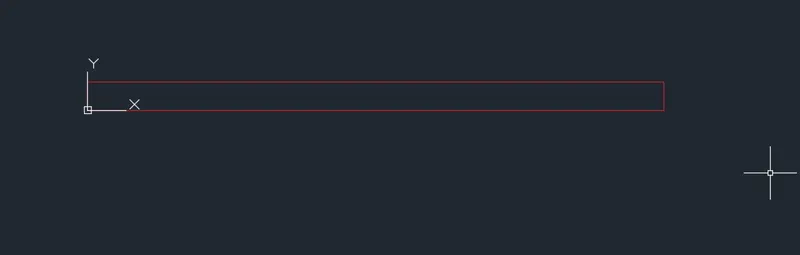
- Type "offset" in the command prompt and press enter.
- Specify the offset distance as2' for the 1st offset and press enter.
- Specify the offset distance as 4'for the next 3 time.
- Select the 1' length to offset and click by keeping the cursor in positive Y direction.
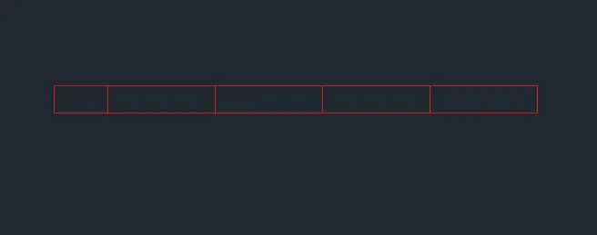
- Repeat the offset for five time by selecting the previous offsetted objects.
- Type "Extend" in the command and extend the required vertical line.
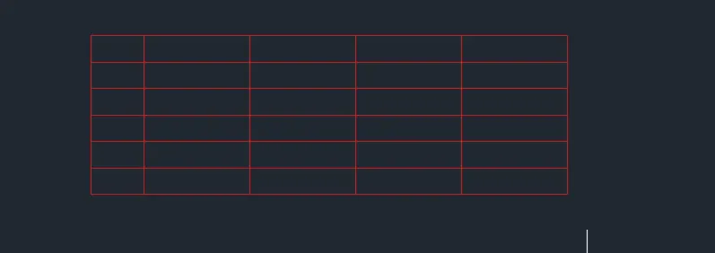
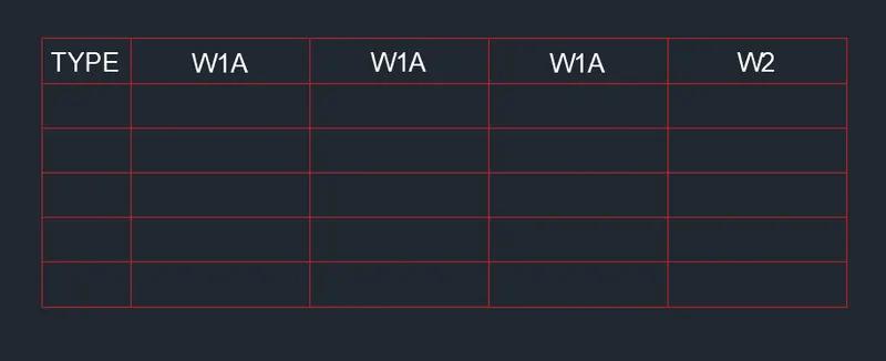
- Select "text" tool from ribbon tab.
- From the drop down list select "single line" text.
- Now the keep the pointer in the left box and click as per the alignment required.
- Type "TYPE" and press enter.
- Click on the next box to insert text.
- Type "W1A" and press enter.
- Click on the next box to insert text.
- Type "W1A" and press enter.
- Click on the next box to insert text.
- Type "W1A" and press enter.
- Click on the next box to insert text.
- Type "W2" and press enter.
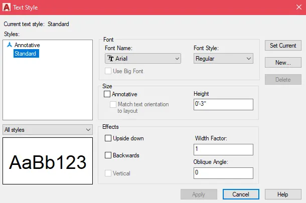
- Type "dimstyle" in the command prompt and press enter.
- From the ribbon tab, select "Annotate".
- Under text, select "manage text styles".
- Specify the text height as 3" and font as "Arial"
- Click ok.
- Select all the objects along with the texts.
- Type "COPY" in the command prompt and press enter.
- Select the top right corner as base point.
- Copy down the selected objects to the bottom right corner and press enter.
- Select the text "TYPE" and double click on it.
- Edit the text as "WIDTH".
- Click on the text "W1A" and edit it as 1'-9".
- Now Click on the next text "W1A" and edit it as 1'-9.5".
- Now Click on the next text "W1A" and edit it as 1'-9.5".
- Now Click on the next text "W2" and edit it as 2'-5 1/2"

- Select the previously created object along with the texts.
- Type "COPY" in the command prompt and press enter.
- Select the top right corner as base point.
- Copy down the selected objects to the bottom right corner and press enter.
- Select the text "WIDTH" and double click on it.
- Edit the text as "BILL".
- Click on the text 1-0" and edit it as 3'.
- Now Click on the next text 1'9.5" and edit it as 3'.
- Now Click on the next text 1'9.5" and edit it as 3'.".
- Now Click on the next text 2'-5 1/2" and edit as 3'-7.5" .

- Select the previously created object along with the texts.
- Type "COPY" in the command prompt and press enter.
- Select the top right corner as base point.
- Copy down the selected objects to the bottom right corner and press enter.
- Select the text "SILL" and double click on it.
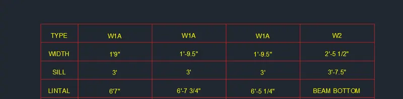
- Edit the text as "LINTEL".
- Click on the text 3' and edit it as 6'7".
- Now click on the text 3' and edit it as 6' 7 3/4".
- Now click on the text 3' and edit it as 6' 5 1/2".
- Now click on the text 3' 7.5" and edit it as BEAM BOTTOM.
- Select the previously created object along with the texts.
- Type "COPY" in the command prompt and press enter.
- Select the top right corner as base point.
- Copy down the selected objects to the bottom right corner and press enter.
- Select the text "LINTEL" and double click on it.
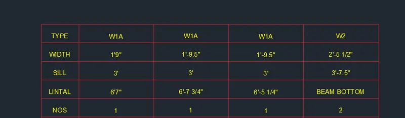
- Edit the text as "NOS".
- Click on the text 6'7" and edit it as 1.
- Now click on the text 6' 7 3/4" and edit it as 1.
- Now click on the text 6' 5 1/2" and edit it as 1.
- Now click on the text BEAM BOTTOM and edit it as 2.
- Select the previously created object along with the texts.
- Type "COPY" in the command prompt and press enter.
- Select the top right corner as base point.
- Copy down the selected objects to the bottom right corner and press enter.
- Select the text "NOS" and double click on it.
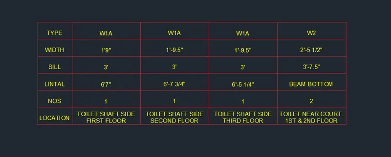
- Edit the text as "LOCATION".
- Click on the text 1 and edit it as TOILET SHAFT NEAR FIRST FLOOR.
- Now click on the text 1 and edit it as TOILET SHAFT SIDE GROUND FLOOR.
- Now click on the text 1 and edit it as TOILET SHAFT SIDE THIRD FLOOR.
- Now click on the text 2 and edit it as TOILET NEAR COURTYARD FIRST SECOND FLOOR.
Q3:
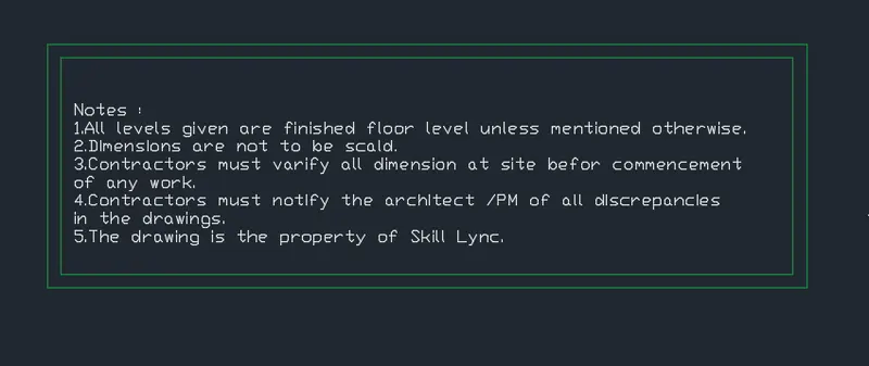
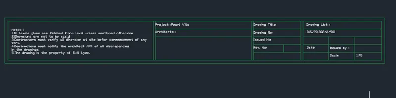
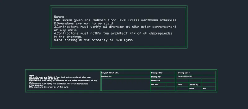
Create the drawing template as shown in the figure:< Use the Notes as in the figure>
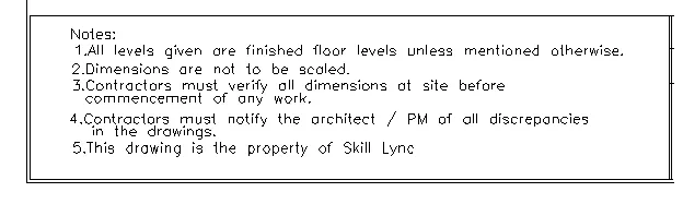

AIM: To create the drawing template as shown in the figure.
Procedure:
- Type "dimstyle" in the command prompt and press enter.
- From the ribbon tab, select "Annotate".
- select modify option.
- Under text, select "manage text styles".
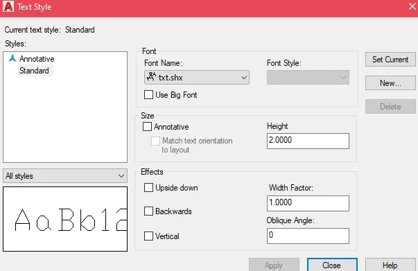
- Specify the text height as 2 and font as "txt.shx"
- Click ok.
- Select line tool from ribbon tab.
- Specify the starting point as (0,0) in the command prompt and press enter.
- Specify the next point as (@145,0) in the command prompt and press enter.
- Specify the next point as (@0,45) in the command prompt and press enter.
- Enter close.To creat a rectangle.
- Creat a offset of 1.5 by clicking off command.
- Select "text" toool from ribbon tab.
- From the drop down list select "Multi line" text.
- Now the keep the pointer in the 1st (left most) box and click as per the alignment required.
- Write down the required note and press enter.
- Select line tool from ribbon tab.
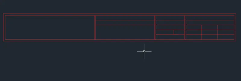
- Specify the Rectangle in the command prompt and press enter rec.
- Specify the starting point and press enter.
- Specify the next as selecting Dimension and press enter.
- Put the length as 190 and width as 20 and press enter.
- Click close.
- Type explode for the rectangle by comanding explode.
- Type offset in the command prompt and press enter.
- Specify the offset distance as 75 and press enter from the left side vertically..
- Type offset in the command prompt and press enter.
- Select the second column line and offset it in Left direction of value 50 vertically..
- Type offset in the command prompt and press enter.
- Select the third column line and offset it in Left direction of value 25 vertically.
- Type offset in the command prompt and press enter.
- Select the 1st horizontal separation line from the top of value 15 .
- Type offset in the command prompt and press enter.
- Select the fourth column line and offset it in Left direction of value 40 vertically.
- Type offset in the command prompt and press enter.
- Select the 1st horizontal separation line from the top of value 13 and do it for 3 time .
- Trimthe unnecessary part from the drawing.
- Select the text tool from ribbon tab.
- From the drop down, select single line text.
- Click on the point from where the text has to start.
- Type the first line and press enter.
- Type the second line and press enter.
- Similarly type all the lines one below the other.
- Select the text tool from ribbon tab.
- From the drop down, select single line text.
- Click on the point from where the text has to start.
- Type "Project: Pearl villas" .
- Place the cursor in the next line and type "Arcitect:".
- Place the cursor where the text has to be inserted next and type "Drawing Title".
- Place the cursor where the text has to be inserted next and type "Drawing No".
- Place the cursor where the text has to be inserted next and type "Issued date".
- Place the cursor where the text has to be inserted next and type "Rev No".
- Place the cursor where the text has to be inserted next and type "Drawing list".
- Place the cursor where the text has to be inserted next and type "Date"Place the cursor where the text has to be inserted next and type Date .
- Place the cursor where the text has to be inserted next and type "Issued by".
- Place the cursor where the text has to be inserted next and type "Scale".
- Place the cursor where the text has to be inserted next and type "1.75".
Result:-
Q4:
Create the list of drawing schedule as shown in the figure:
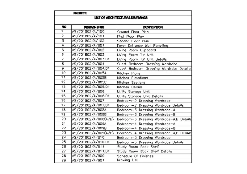
Aim: To create the list of drawing schedule as shown in the figure.
Procedure:
- Type "units" in the command prompt and press enter.
- Select the units as "Architectural" and click ok.
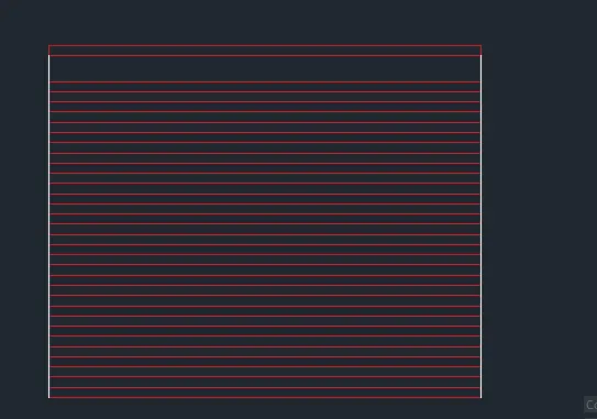
- From the ribbon tab, select the line tool.
- Specify the starting point in the workspace.
- Specify the next point as (@340",0) in the command prompt and press enter.
- Specify the next point as (@0,-8") in the command prompt and press enter.
- Specify the next point as (@-340",0) in the command prompt and press enter.
- Specify the next point as (@0,8") in the command prompt and press enter.
- Type "offset" in the command prompt and press enter.
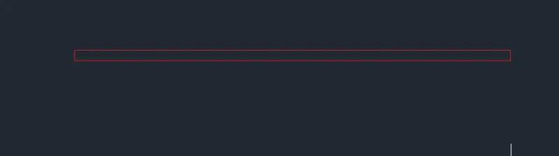
- Specify the offset distance as 20" in the command prompt.
- Select the bottom line to offset.
- Type "offset" in the command prompt and press enter.
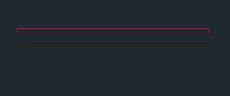
- Specify the offset distance as 8" in the command prompt.
- Select the bottom line to offset.
- Similarly do offset for all the lines.

- Select line tool from ribbon tab.
- Connect all the lines on both the sides.
- Type "offset" in the command prompt and press enter.
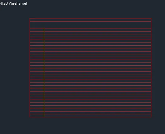
- Specify the offset distance as 40" in the command prompt.
- Select the left vertical line to offset.
- Type "offset" in the command prompt and press enter.
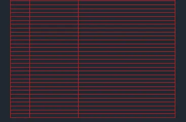
- Specify the offset distance as 100" in the command prompt.
- Select the previously offsetted vertical line to offset.
- Type "offset" in the command prompt and press enter.
- Specify the offset distance as 100" in the command prompt.
- Select the previously offsetted vertical line to offset.
- Select the Annotate tool from the ribbon tab.
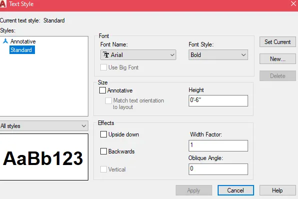
- Select "Manage text style" from the drop down list available.
- Select the font name as "Arial" and font style as "bold".
- Enter the text height as 6" and click ok.
- Select the text tool from ribbon tab.
- From the drop down list, select the "single line".
- Click on the cursor to start entering the text.
- Text pointer appears, enter the text as "Project".
- Click on the cursor to start entering the next text.
- Text pointer appears enter the text as "LIST OF ARCHITECTURAL DRAWINGS"Text pointer appears, enter the text as LIST OF ARCHITECTURAL DRAWINGS .
- Click on the cursor to start entering the next text.
- Text pointer appears, enter the text as "NO".
- Click on the cursor to start entering the next text.
- Text pointer appears, enter the text as "DRAWINGS".
- Click on the cursor to start entering the next text.
- Text pointer appears, enter the text as "DESCRIPTION".
- Select all the texts using cursor.
- In the ribbon tb, go to properties section.
- Click "By layer" in the properties.
- Select the color as "black".
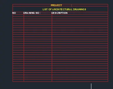
- Similarly to type the given text in the workspace use text tool.
- Select the text tool from ribbon tab.
- From the drop down list, select the "single line".
- Click on the cursor to start entering the text.
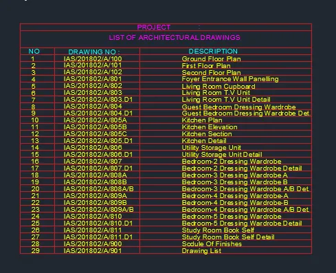
Result :-
Q5:
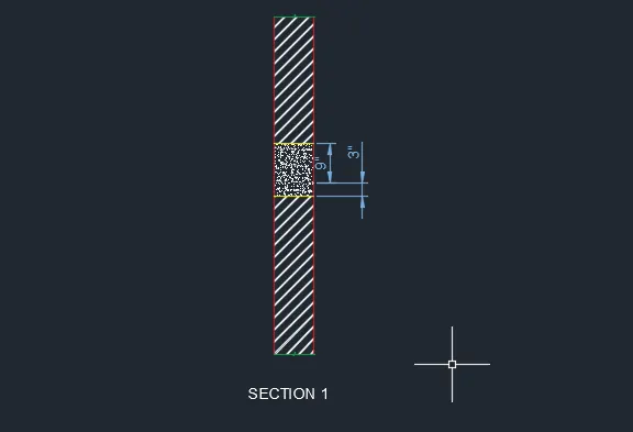
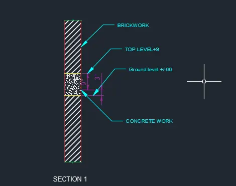
Create the Beam detail as shown in the figure and provide text wherever given.
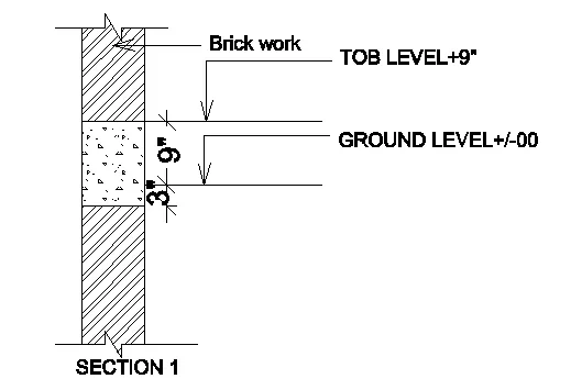
AIM: Create the Beam detail as shown in the figure and provide text for Top level and Ground level wherever given.
PROCEDURE:
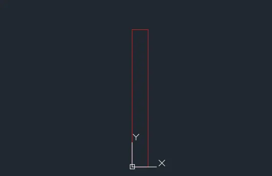
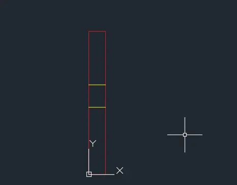
- Select line from the ribbon tab.
- Specify the starting point as (0,0) in the command prompt and press enter.
- Specify the next point as (@0,3') in the command prompt and press enter.
- Specify the next point as (@0,3") in the command prompt and press enter.
- Specify the next point as (@0,9") in the command prompt and press enter.
- Specify the next point as (@0,2.4') in the command prompt and press enter.
- Specify the next point as (@9",0) in the command prompt and press enter.
- Specify the next point as (@0,-2.4') in the command prompt and press enter.
- Specify the next point as (@0,-9") in the command prompt and press enter.
- Specify the next point as (@0,-3") in the command prompt and press enter.
- Specify the next point as (@0,-3') in the command prompt and press enter.
- Specify the next point as (@-9",0) in the command prompt and press enter.
- Type "line" in the command prompt and press enter.
- Specify the starting point as (0,3') in the command prompt and press enter.
- Specify the next point as (@9",0) in the command prompt and press enter.
- Press "esc".
- Type "line" in the command prompt and press enter.
- Specify the starting point as (0,4') in the command prompt and press enter.
- Specify the next point as (@9",0) in the command prompt and press enter.
- Press "esc".
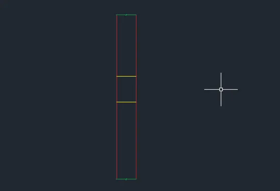
- Make the top and bottom line of the drawing as brake line use the command BREAKLINE .
- Draw the top and bottom line as break line.
- Press Esc.
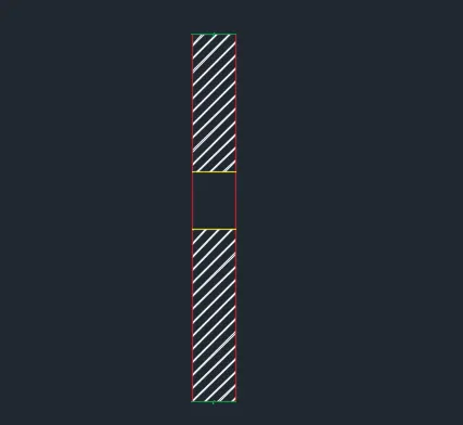
- Type "hatch" in the command prompt and press enter.
- Hatch creation tool box opens.
- From the pattern menu, select the suitable hatch as given in the figure to represent brick work.
- Move the pointer to the closed area to be hatched and click to hatch the layer.
- Adjust the scale to view the hatch.
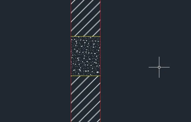
- Type "hatch" in the command prompt and press enter.
- Hatch creation tool box opens.
- From the pattern menu, select the suitable hatch as given in the figure to represent concrete.
- Move the pointer to the closed area to be hatched and click to hatch the layer.
- Adjust the scale to view the hatch.
- Select dimension tool from ribbon tab to measure the dimensions.
- Select the first point and drag the pointer to specify the next point.
- Now the tool displays the dimension.
- Similarly to type the given text in the workspace use text tool.
- Select the Annotation tool from ribbon tab.
- From the drop down list, select the "leader".
- Click on the cursor to start the leader and adjust the height using cursor.
- Enter the text as "Ground level +/-00".
- Similarly to type the given text in the workspace use text tool.
- Select the Annotation tool from ribbon tab.
- From the drop down list, select the "leader".
- Click on the cursor to start the leader and adjust the height using cursor.
- Enter the text as TOP LEVEL+9".
- Similarly to type the given text in the workspace use text tool.
- Select the Annotation tool from ribbon tab.
- From the drop down list, select the "leader".
- Click on the cursor to start the leader and adjust the height using cursor.
- Enter the text as "BRICKWORK".
- Select the text tool from ribbon tab.
- From the drop down list, select the "single line".
- Click on the cursor to start entering the text.
- Enter the text as " Section 1".
RESULT :