Sketch a G+1 residential plan according to Vaastu Shastra and Calculation of Loads as per IS code
Aim:
- To sketch a G+1 floor residential plan according to Vastu Shastra and to list down the names of structural drawings required to be provided to the site of construction.
- Assume the size of structural elements ( column,beam ,slab etc.) and accordingly calculate the individual corresponding loads from the members according to IS code.
Drawing:
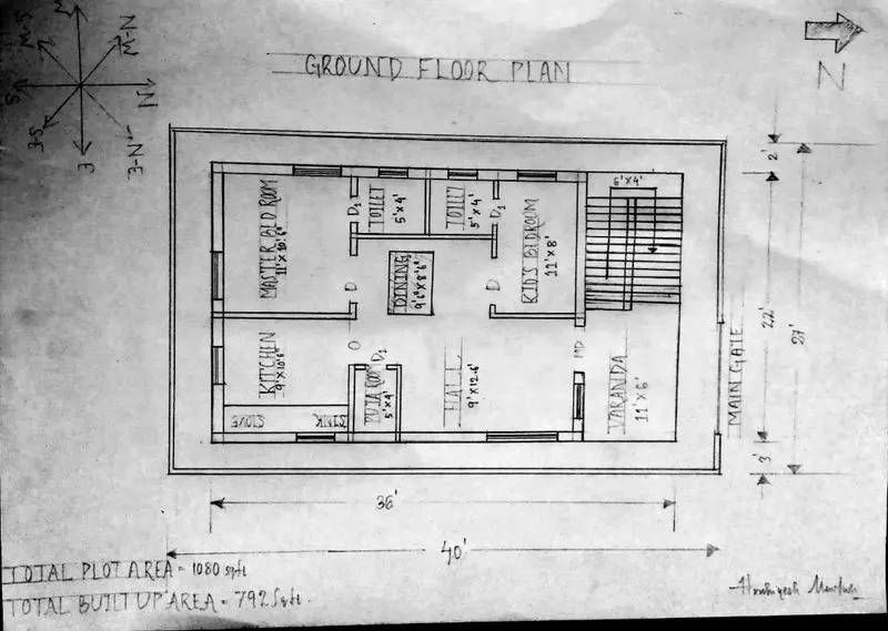
1:Ground floor plan
2:First floor plan
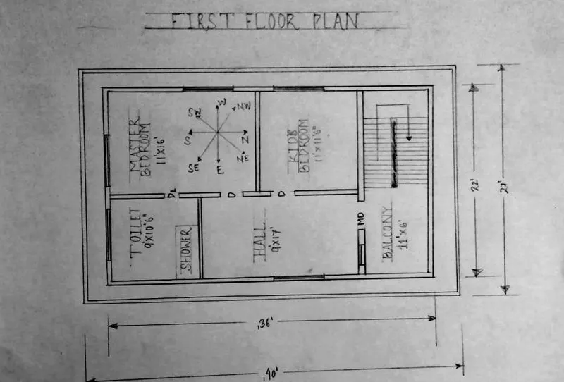
- Thickness of internal wall : 0.15 m
- Thickness of external wall : 0.23 m
- Thickness of slab : 0.25 m
- Dimension of column : 0.3m x 0.3 m
- Dimension of beam: 0.3m x 0.45m
- Height of wall of each floor: 4.5 m
Vaastu Shastra
- Vaastu Shastra is the ancient Indian science of architecture and acts as a guideline to design your home in the way that enhances Posative energy.
- Our nature is bundant with powerhouse of energy sources like sun,wind,moon,water,earth and fire.
- Effect of sun ray.flow of wind pull of earth's magnatic field and other such cosmic energies.
- Agiid home needs to radiate the right kind of energy.
- A person dwelling in a house comes under the influence of a specific energy field which comes under the influence of specific energy field.
- Architectural changes are not possible for a ready to move in house.
Significance of Eight directions:
Four cardinal direction
- North
- South
- East
- West.
Four intercardinal direction
- North-East
- North-West
- South-East
- South-West.
Each direction signifies an aspect of life and is governed by various gods.
- North : Wealth
- South: Dharma
- West and East : overall prosperity
Principle of Vastu Sastra :
- Shape: Rooms should be preferably be square or rectangle.
- Room Basics: Room should be airy,well lit,bright and clean.
- Home center: Center of the house should be an empty space.
- Stair and Furniture: Heavy furniture should be kept in the south west direction.
- Water: Avoid keeping plants and water features in bedroom.
- Dining Table : Dining space should be near the kitchen and not near the main door.
- Mirror placement : Mirror placement is bed is strictly not allowed.Mirror in the bed room need to be placed in such a way that the bed canot be seen.
Auspicious direction as per Vastu sastra
|
|
|
|
|
|
|
|
|
|
|
|
|
|
|
|
Drawings importance in construction
- Different types of drawings is used in construction such as architectural drawings, structural, electrical, plumbing and finishing drawings.
- These drawings provides layout plans and details for construction of each and every part of the building.
- Drawings plays an important role in the construction field to convey the ideologies and perspective of the designer to the layman at site.
- The drawings may be used to indicate the overall appearance, inside or outside the structure, or they may be used to indicate precise measurements and other details for construction.
Types of Construction Drawings
- There are different type of drawing used for the construction process. Depending upon the purpose they serve, construction drawings are divided into 5 types
- 1. Architectural Drawing
- 2. Structural Drawing
- 3. Electrical Drawing
- 4. Plumbing Drawing
- 5. Finishing Drawings
1. Architectural Drawing
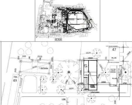
- Location site plan
- Setting out plan
- Levations
- Sections and other details.
- This is primary drawing used for marking out the plan on the ground. It represents the location, orientation and information about the site’s topography, landscaping utilities ,and site work.
1.2 Working Plan
- This drawing gives the information of horizontal dimensions of the building, thickness of walls, clear spaces inside the building and column locations.
- it also shows the openings required in the building such as doors, windows and ventilators.
- Section drawings represents the material of construction to be used, heights and measurement of the different components of buildings, type of structural components such as type of slab , etc.
- Its represents the drawing when the building is cut through a vertical plane.
- Elevation drawing represents the information of openings, size and shape of external surface, height of building and finish of the building after completion.
- These drawings are made by having a aesthetic view of the building.
- Structural drawings can be termed as the backbone drawing of the building.
- It consists all the information about the structural intervention that are coming on a building.
- It contains many type of drawing with very minute details and description.
- This is more of a codes and by laws of the buildings.
- No drawing is found in this, but the details of all the structural drawings are mention in this such as concrete mix, lapping length, curing time, abbreviation, codes and other work procedures.
- This Drawing represents the footing excavation dimension, column position, footing plan and grid lines of column.
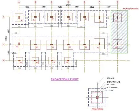
Excavation Layout
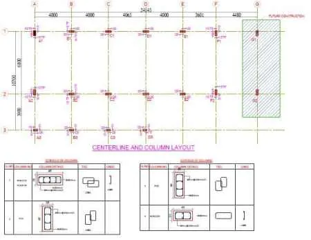
2.3 Column Layout
- This drawing represents the position and orientation of columns and column reinforcement details.
- This drawing represents the dimensions, position and section of plinth beam and the details of reinforcement in plinth beam.
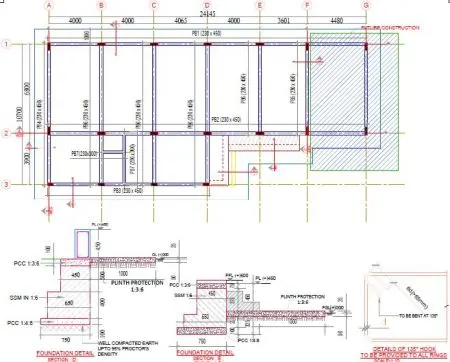
Plinth Beam Layout
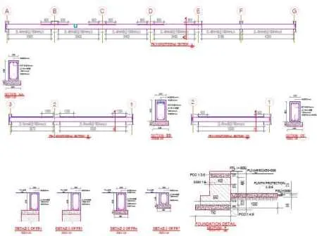
2.4 Lintel Beam Layout
- This drawing represents the dimensions, position and section of lintel beam and the details of reinforcement in lintel beam.
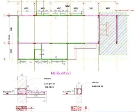
Lintel Beam Layout and Details
2.5 Roof Beam and Shuttering Layout
- This drawing represents the details of reinforcement of roof beam, its section and shuttering details.
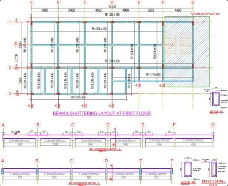
Roof Beam and Shuttering Layout
2.6 Roof Slab Layout
- This drawing represents the details of reinforcement of roof slab, its section and openings in the roof for various purpose such as stairs or skylight.
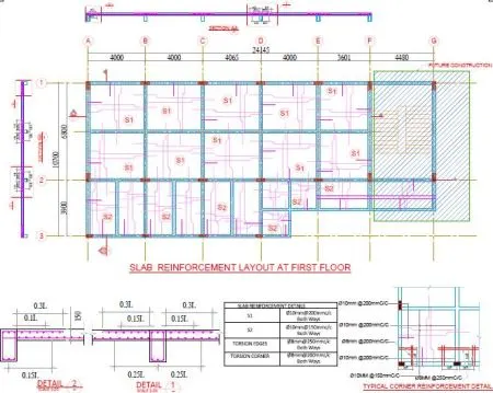
Roof Slab Layout
3. Electrical Drawing
- Electrical drawing represent the details of electrical fixtures, location of switches, fan, light and others.
- It also represents the load calculation, tapping for electricity, wiring path and other interventions such as AC and UPS and its components.
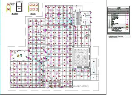
Electrical Drawing
4. Plumbing Drawing
- Plumbing drawings give the location of sanitary, piping for water supply system, fixture, and the process to connect every fixture.
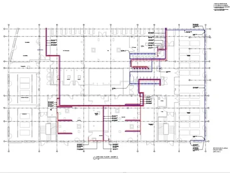
Plumbing Drawing
5. Finishing Drawings
- Finishing drawings represents the finish type of every component of the building such as flooring pattern, painting color, false ceiling shape, plastering texture and elevation design.
- These details are sometime given in elevation drawings also.
- There is no standard rule of drawings required for a project.
- Depending upon the type of building and requirement, types of drawings are made and issued .
TYPES OF LOADS ON R.C.C. STRUCTURES
Structures are designed to withstand various types of loads. The various types of loads expected on a structure are as follows :
(i) Dead loads
(ii) Live loads or imposed loads
(iii) Wind loads
(iv) Snow loads
(v) Earthquake loads
Dead Loads
- Dead loads are due to self weight of the structure. Dead loads are the permanent loads which are always present. Dead loads depends upon the unit weight of the material. Dead loads includes, the self weight of walls, floors beams, columns etc. and also the permanent fixtures present in the structure.
- The unit weight of commonly used building materials are given in the code IS 875 (part-I)-1987. The unit weights of important building materials are given in Table 1.11.
Unit Weights of Common Building Materials
| S.No. | Material | Unit Weight kN/m3 |
| 1. | Plain Cement Concrete | 24 |
| 2. | Reinforced Cement Concrete Steel | 25 |
| 3. | Steel | 78.5 |
| 4. | Brick Masonry (Cement Plaster) | 20 |
| 5. | Stone Masonry Granite | 24 |
| 6. | Asbestos Cement Sheets | 0.13 |
| 7. | Cement
(i) Ordinary Portland (ii) Rapid Hardening |
14.10
12.55 |
| 8. | Lime Concrete | 19.2 |
| 9. | Mortar (i) Cement
(ii) Lime |
20.4
16 |
| 10. | Marble | 26.7 |
| 11. | Glass | 27 |
| 12. | Timber (i) Chir
(ii) Deoder (iii) Teak (iv) Sal |
5.65
5.35 6.28 8.5 |
| 13. | Bitumen | 0.102 |
| 14. | Surkhi (Brick dust) | 9.9 |
| 15. | Sand Stone | 22.0-23.5 |
Live loads
- Live loads on floors and roofs consists of all the loads which are temporarily placed on the structure, For example, loads of people, furniture, machines etc. Live loads keep on changing from time to time. Live loads are also called as imposed loads. Various types of imposed loads coming on the structure are given in IS 875 (Part-2): 1987. The imposed loads depend upon the use of building. Some of the important values of live loads are given in Table 1.12.
TABLE 1.12. Minimum Live Loads to be Considered
| S.No. | Occupancy | UDL Load |
| 1. | Bath rooms and toilets in all types of building | 2 kN/m2 |
| 2. | Living and bed rooms | 2 kN/m2 |
| 3. | Office rooms in :
(i) Hostels, hotels, hospitals and business building with separate store (ii) In assembly buildings |
2.5 kN/m2 3 kN/m2 |
| 4. | Kitchens in : (i) Dwelling houses
(ii) Hostels, hotels and hospitals |
2 kN/m2
3 kN/m2 |
| 5. | Banking halls, class rooms, X-ray rooms, operation rooms | 3 kN/m2 |
| 6. |
Dining rooms in (i) educational buildings, institutional and mercantine buildings (ii) Hostels and hotels |
3 kN/m2 4 kN/m2 |
| 7. | Corridors, passages, stair cases in:
(i) Dwelling houses, hostels and hotels (ii) Educational institutional and assembly building (iii) Marcantine buildings |
3 kN/m2 4 kN/m2 4 kN/m2 |
| 8. | Reading rooms in libraries :
(i) With separate storage (ii) Without separate storage |
3 kN/m2 4 kN/m2 |
| 9. | Assembly areas in assembly buildings :
(i) With fixed seats (ii) Without fixed seats |
5 kN/m2 5 kN/m2 |
| 10. | Store rooms in educational buildings | 5 kN/m2 |
| 11. | Store room in libraries | 6 kN/m2 for a height of 2.24+2 kN/m2 for every 1 m additional height |
| 12. | Boiler rooms and plant rooms in :
(i) Hostels, hotels, hospitals, mercantine and industrial buildings (ii) Assembly and storage buildings |
5 kN/m2 7.5 kN/m2 |
| 13. | Roof loads (Flat, sloping with slopes upto 10 degrees):
(i) Access provided (ii) Access not provided |
1.5 kN/m2 0.75 kN/m2 |
| 14. | Sloping roof with slope greater than 10 degree | For purlins – 0.75 kN/m2 less 0.02 kN/m2 for every degree increase in slope over 10 degrees |
Wind load
- The force exerted by the horizontal component of wind is to be considered in the design of building. Wind loads depends upon the velocity of wind, shape and size of the building. The method of calculating wind loads on structure is given in IS 875 (Part-3):1987.
Snow Loads
- The building which are located in the regions where snowfall is very common, are to be designed for snow loads. The code IS 875 (Part-4):1987 deals with snow loads on roofs of the building.
Earthquake Loads
- Earthquake loads depend upon the place where the building is located. As per IS 1893-2002 (Part-I) (General Provisions for Buildings), India is divided into four seismic zones. The code gives recommendations for earthquake resistant design of structures. Now, it is mandatory to follow these recommendations for design of structures.
Calculation LOADS ON R.C.C. STRUCTURES
Dead load
- Self weight
- Floor finish load
- Partition wall load
- Main wall load
- Sunkslab load
1.Self weight
- Self weight of slab :
- Self weight of slab = Slab thickness* Unit weight of RCC
- Thickness of slab =250 mm = 0.25m
- For calculating self load for slab we have require self weight of concrete that is 25 kN/m3
- RCC slab and self weight of Steel that is approx 80 kN/m3
Calculate self weight of slab
Calculation :-
-
Self weight of slab is equal to weight of concrete in slab and weight of Steel which is used in construction of slab. First we calculate weight of concrete in slab.
(A) weight of concrete used in slab
- Thickness of slab = 0.25 m
- Weight of concrete = thickness ×Unit weight of RCC
- Weight of conc =0.25 m×25kN/m3
- Weight of conc = 6.25 kN/m^2
We should convert in kilo Newton we get load applied by concrete in slab is about 6.25 kN/m2
B) Now calculate weight of Steel used in slab by Thumb Rule we know that approx 1% of concrete steel is used in slab
- Density of steel = 80kN/m3
- Volume of steel is 1% of concrete
- Weight of steel = 0.01×0.25 m×80kN/m3
- Weight of steel = 0.2 kN/m2
- Now convert kilo per metre into kilo Newton so load applied by Steel in slab is approx 0.16kN
- Now total self weight of slab is equal to weight of concrete and weight of Steel
- Total weight = 6.25 + 0.2 kN/m3
- Total weight = 6.45 kN/m3
Now total self load of slab is about 6.45 kN/m3 acting on column.
Self weight of Beam :
- Self weight of beam = Beam width * Beam depth *clear span Unit weight of RCC
- Beam size =300mm * 450 mm
- Assume Clear length of Beam = 5 m
- Self weight of beam =0.300 m * 0.450 m * 5m * 25 KN/M^3 =16.87 KN
Now total self load of beam is about 16.87 kN /m2 acting on column.
Self weight of column :
- Self weight of column = column width * column depth *column length* Unit weight of RCC
- Lets assume column length 3m
- Size of column = 300mm * 300mm
- Assum Height of column=4m
- Volume of concrete = 0.3*0.3m*4m
- Volume of concrete= 0.28 m3
- Weight of concrete = volume×density
- Weight of conc =0.28 m3×25kN/m3
- Weight of conc = 7 kN
We should convert in kilo Newton we get load applied by concrete in column is about 7 kN
B) Now calculate weight of Steel used in column by Thumb Rule we know that approx 1% of concrete steel is used in column
- Density of steel = 80 kN/m3
- Volume of steel is 1% of concrete
- Weight of steel = 0.01×0.28m3×80 kN/m3
- Weight of steel = 0.224 kN
- Now total weight of column is equal to weight of concrete and weight of Steel
- Total weight = 7 + 0.224 kN
- Total weight = 7.224 kN
Now total self load of column is about 7.224 kN acting on column
2.Floor finish load
- Thickness of the floor finish =50mm
- Unit weight of concrete mortar=20 KN/m^3 (IS-875-Part-I)
Self weight of floor finish = 0.05 m * 20 KN/m^3 =1KN/m^2
3.Partition wall load
- Thickness of partition wall =100mm
- Hight of wall =4.5 m
- Unit waight of brick masonary =20 kN/m^3 (IS -875-Part I)
weight of partition wall =0.1 m *4.5 m *20 kN/m^3 = 9kN/m (on the beam)
4.Main [External wall] wall load
- Thickness of the wall = 0.23m (Assume)
- Hight of the wall = 4.5 m
- Unit weight of Brick mesonary =20 KN/m^3 (IS -875-Part I)
weight of wall = 0.23m * 4.5m *20 KN/m^3 = 20.7 KN/m
5.Internal wall load
- Thickness of the wall = 0.15m (Assume)
- Hight of the wall = 4.5 m
- Unit weight of Brick mesonary =20 KN/m^3 (IS -875-Part I)
weight of wall = 0.15m * 4.5m *20 KN/m^3 = 13.5 KN/m
6.Sunk slab load
- Thickness of Sunk slab = 250 mm (Assume)
- Sunk cinder filling =8 KN/m^3 (IS -875-Part I)
weight of sunk Slab =0.25 m * 8KN/m^3 =2.0 KN/m^2
Live load
- Live loads on floors and roofs consists of all the loads which are temporarily placed on the structure.
- For example, loads of people, furniture, machines etc. Live loads keep on changing from time to time.
- Live loads are also called as imposed loads. Various types of imposed loads coming on the structure are given in IS 875 (Part-2): 1987
| Occupancy | Loading |
| All rooms and kitchen | 2.0 KN/m^2 |
| Toilets and bathroom | 2.0 KN/m^2 |
| Corriders,Passage,Terrace | 3.0 KN/m^2 |
| Store room in recidential building | 3.0 KN/m^2 |
Wind load
- Wind load is primarily horizontal load caused by the movement of air relative to earth.
- Wind load is required to be considered in structural design especially when the heath of the building exceeds two times the dimensions transverse to the exposed wind surface.
- For low rise building say up to four to five stories, the wind load is not critical because the moment of resistance provided by the continuity of floor system to column connection and walls provided between columns are sufficient to accommodate the effect of these forces.
- Wind load is designed only when the height of building exceed 10 m .
The height of building design is 9m which is less than 10m so, we will not consider wind load.
Codes referred :
- IS 875:1987 (PART 1) for Dead load
- IS 875:1987 (PART 2) for Live load
- IS 875:1987 (PART 3) for Wind load
- IS 456:2000 for RCC
Result:
- The plan is designed by considering Vastu Shastra concept.
- The load calculations are done as per IS code consideration.