Creating a Residence Layout, Seating plan, Toilet and Utility room plan using AutoCad
Aim:
- This challenge aims to show the application of the AutoCAD software in the Civil Engineering industry.
- In this challenge, the AutoCAD software is applied in the sketching of a Residence Layout, Seating Plan, and Toilet Rooms. With the combination of the different AutoCAD tools, the sketch can be provided easier and faster.
- The amount of knowledge in using the different AutoCAD software tools will prove useful in these situations.
- This challenge aims to show how these tools are utilized in the following Drawing.
Introduction:
The AutoCAD software provides different tools. The tools used in this challenge is as described below:
- Line - Creates line object
- Rectangle - Creates rectangle object
- Circle - Create circle object
- Trim - Cut unwanted lines or shapes with the provided cutting edges.
- Extend - Extend lines to opposite corners.
- Move - Move objects to particular locations.
- Copy - Copy objects to particular locations.
- Rotate - Rotate selected objects to a particular angle with respect to base point.
- Array - Copy an object in a set path linearly or polarly.
- Dimlinear (DLI) - Provides vertical or horizontal linear/straight dimensions.
- Leader - Creates an arrow head line.
- Layers - Provide identification of line or object groups by their properties.
- Units - Open "Drawing Units" window to specify the drawings units.
- Dimstyle - Open "Dimension Style Manager" window to modify the dimension properties.
Layers:
- The layers are important in the sketch to distinguish the objects.
- The layer can also be used to specify the lines within the given group so that working with the sketch will be easier. The following layers will be used in Sketch 1 and 2
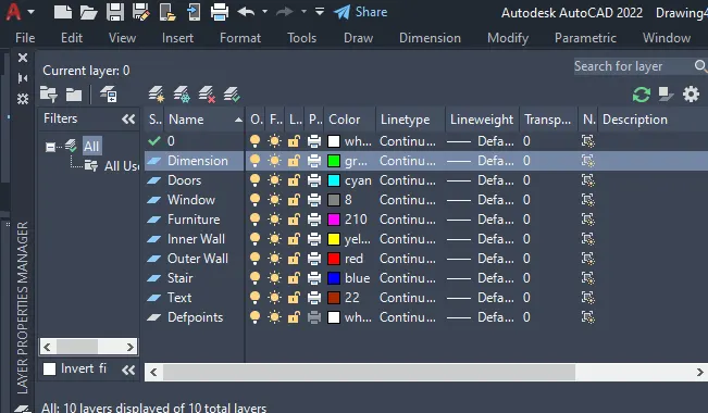
- To see the layers, the "Layer" command is typed in the command prompt.
- The icon tools inside the opened layer window are easy to understand like "Add Layer", "Delete Layer" and "Set Current". They are self-explanatory so this window is easy to use.
- The layer properties can be specified as shown above. Color, Lintype, Lineweight, Transparency, and many more properties can be altered.
Sketch and Procedure
A. SKETCH 1 – Residence Layout
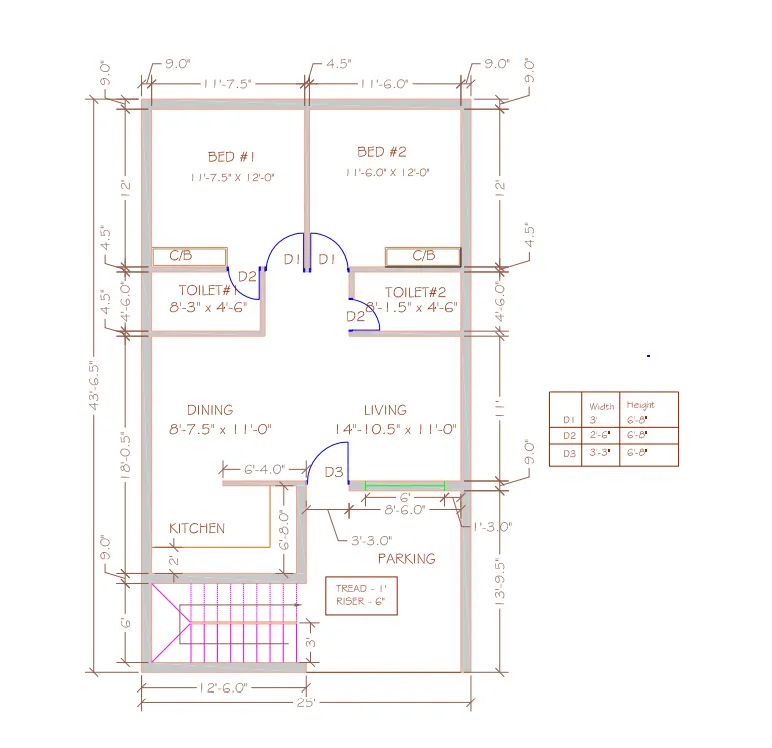
Challenge 1 - Residence Plan: Sketch the layout of a residence as shown in the Figure 1. Consider all dimensions as reference to sketch the unit plan. Also, the text in the layout are only for reference. Assume the missing dimensions. Also, refer the schedule for size of the
doors.
PROCEDURE:
- Set units to "Engineering".
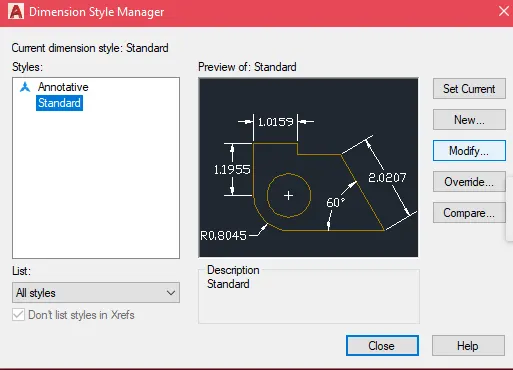
- Type "dimstyle" in the command prompt.
- The "Dimension Style Manager" will appear.Select modify .
- Set current.Close
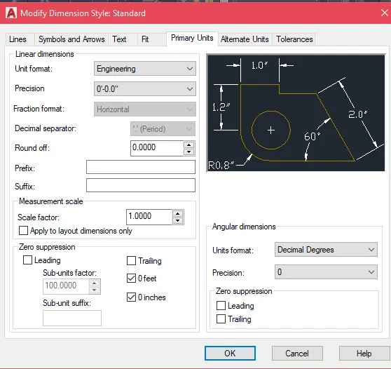
- In the new window, go to the "Primary Units" tab and change the "Unit Format" to Engineering.
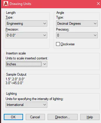
- Then enter LIMIT
- specify lower left corner as <0'00",0'00">
- specifyUpper right corner as <50'00",50'00">
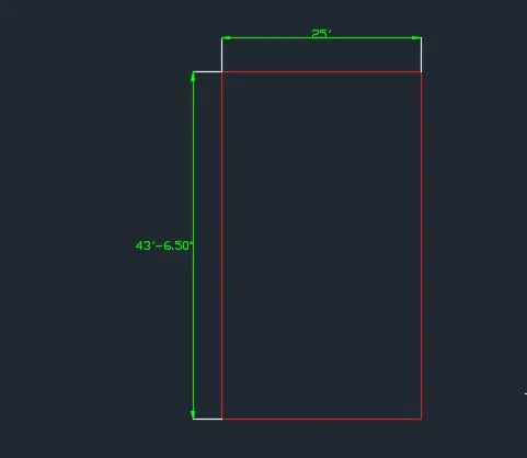
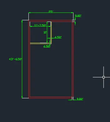
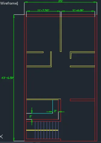
- Now create the boundary element. Using the rectangle tool, create a rectangle with 25' width and 43'-6.5" length
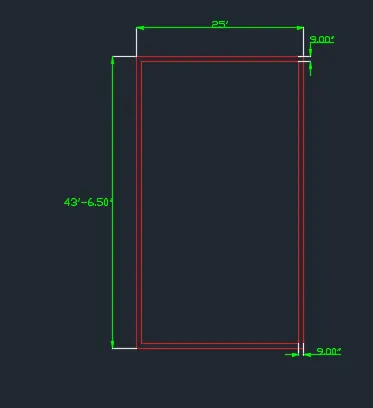
- Now create the outer walls.
- Use the offset tool and offset the created rectangle by 9".
- After creating the inner rectangle, select all and Explode the rectangles.
- This will make the rectangle object to be separated into lines.
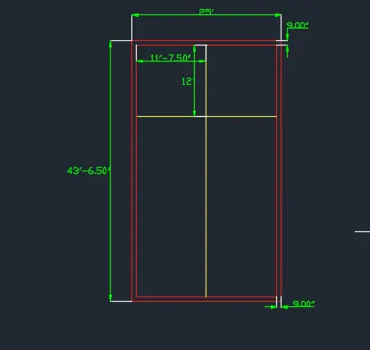
- Create the inner boundary of Beddroom 1.
- Select the left inner wall line and offset it by 11'7.5" to the right.
- Select the upper inner wall line and offset it by 12' downward
- Trim the edges using the fillet tool with 0 radius to create the inner boundary of bedroom 1.
- Then select both lines and offset by 4.5" outwards.
- Again, use the fillet tool with 0 radius for the newly created line
- Create the inner boundary of Toilet 1.
- Select the lower outer wall of bedroom 1 and offset 4'-6" downward.
- Select the left innerwall of the boundary element and offset 8'-30" to the right
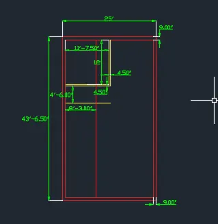
- Trim the edges to create the inner boundary of the Toilet 1 .
- Do the procedures used in bedroom 1 to create the wallof the Toilet.
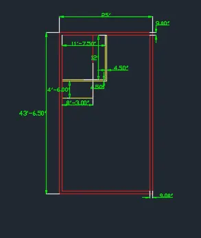
- The inner wall thickness is 4.5".
- To trim, select trim tool and press enter to select all as cutting edges.
- To create the corner of the rectangle, use the fillet tool with 0 radius.
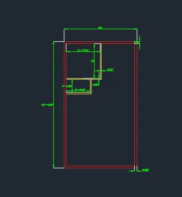
- Proceed with the door openings.
- Select the right inner wall line of Toilet 1.
- Offset the line 2'-6" to the left using the offset tool.
- When using the copy tool, make sure the Ortho Mode is on.
- Also, extend the right inner line of the bedroom wall to the outer line wall using the extend tool.
- To extend the line, select the
- Extend tool. Press enter to select all as boundary edges
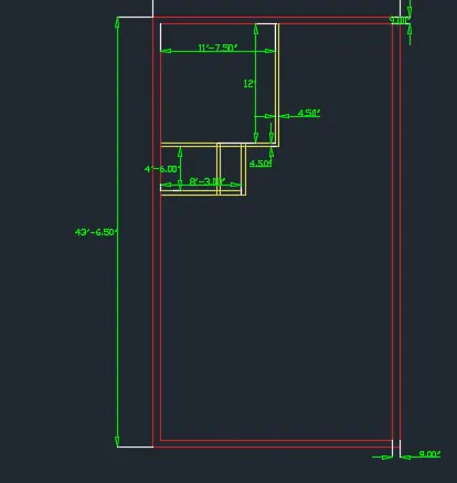
- Using the trim tool, trim the unnecessary lines.
- Select Trim tool and press enter to select all as cutting edge
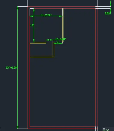
- Select the inner walls of Toilet 1.
- Select the mirror tool. First point of mirror line: Center of vertical inner wall.
- Second point of mirror line: Any point downward
(Make sure Ortho Mode is turned on)
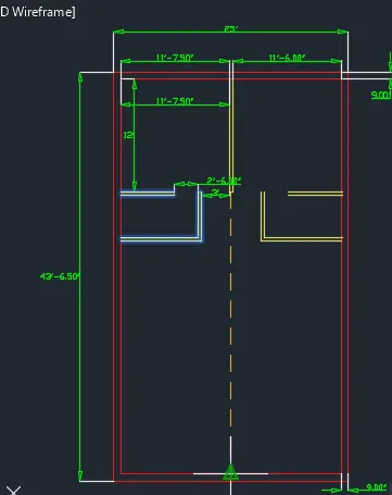
- Use the fillet tool with 0 radius to enclose the rectangle.
- This is the Toilet 2 area. Above this area is Bedroom 2.
- Now extend the lower inner line of Toilet 2 to the outer line.
- Once it is extended, select the line and offset/copy it 2'-6" upward.
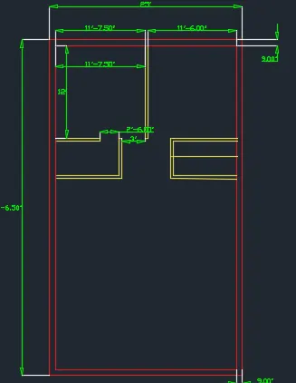
- Select Trim tool and press enter to select all as cutting edges.
- Delete the unncessary lines to form the opening of Toilet 2.
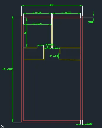
- Using the offset or copy tool, create the wall lines for the below area.
- Select the two lower external lines of Toilet 1 and 2. Select copy tool and point downward (make sure Ortho Mode is on).
- Copy distance is 11'.
- Using a similar method.
- Select the two new created lines and copy or offset 4.5" for the left line and 9" for the right line
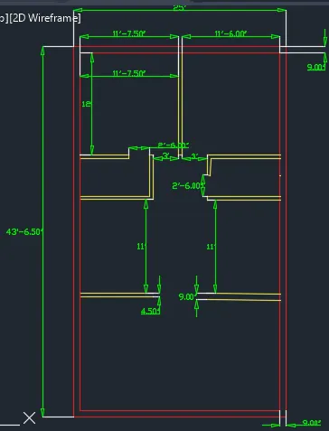
- Using the copy method as specified above, copy the created line object on the left 6'-8" downward.
- Similarly, offset the newly created line 9" downward.
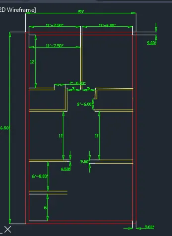
- With the same method, select the right inner line object of the Outer Wall and copy it 8'-6" to the left.
- Similarly,from that line take a offset of 3'30" toward left direction.
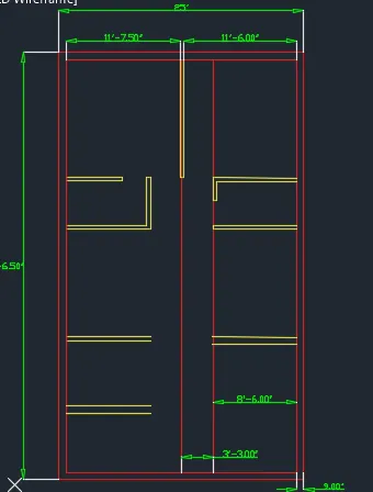
- Use the fillet tool to connect the upper most created line and the vertical lines as shown below.
- Trim unnecessary part.
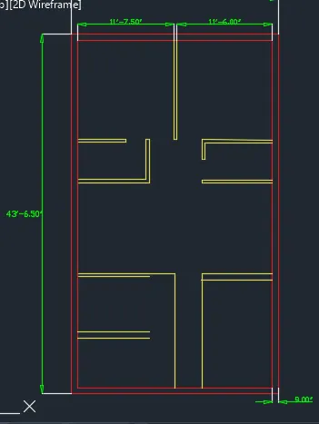
- Extend the left vertical line to the outer wall using the extend tool.
- Offset the left vertical line 9" to the left
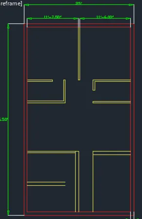
- Extend the horizontal lines to the vertical lines using the extend tool.
- You can select all as boundary edges by pressing enter after the command.
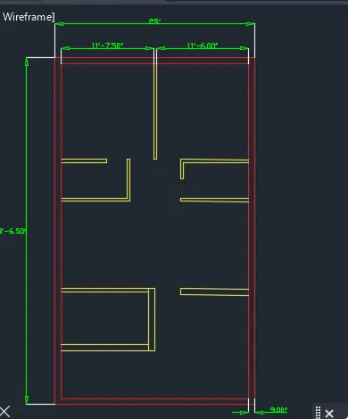
- Using the Trim tool, delete the unnecessary lines.
- The kitchen walls will be created
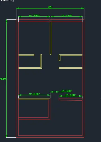
- Create the Kitchen Counter.
- Select the inner wall line object of the Kitchen and offset it inward by 2'.
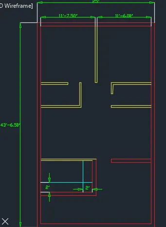
- To finish the Kitchen counter table, use the fillet tool with radius 0.
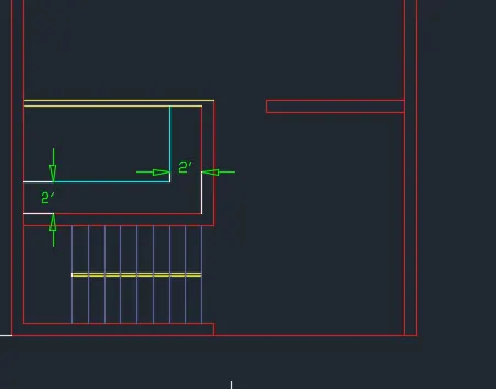
- For the Stair area, use the Line tool to connect the lower right corner of the kitchen wall to the corner created below when the Outer wall is trimmed.
- Aside from that, copy the lower external wall of the kitchen 3' downwards for stair.
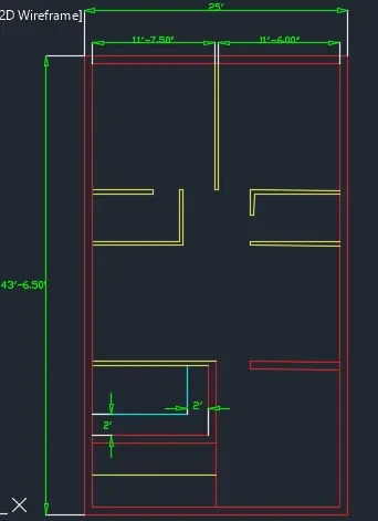
- For the Parking area, use the trim tool to delete the inner line of the Outer wall.
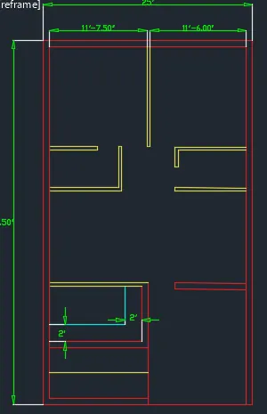
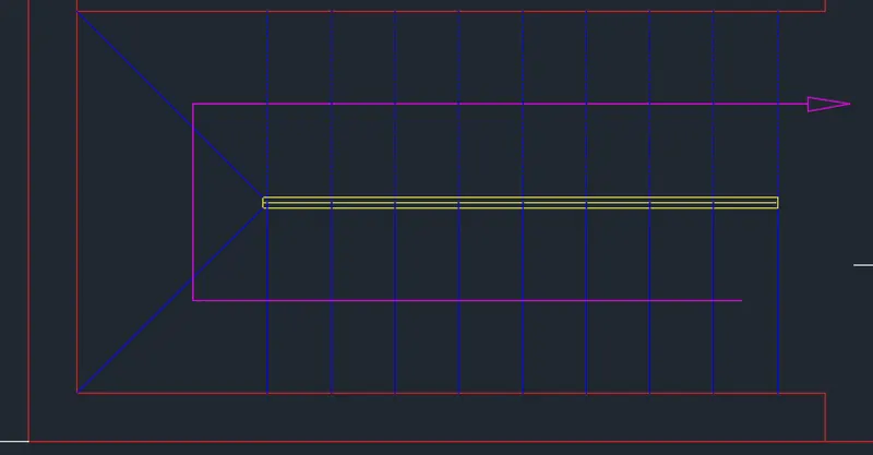
- Create the Stairs.
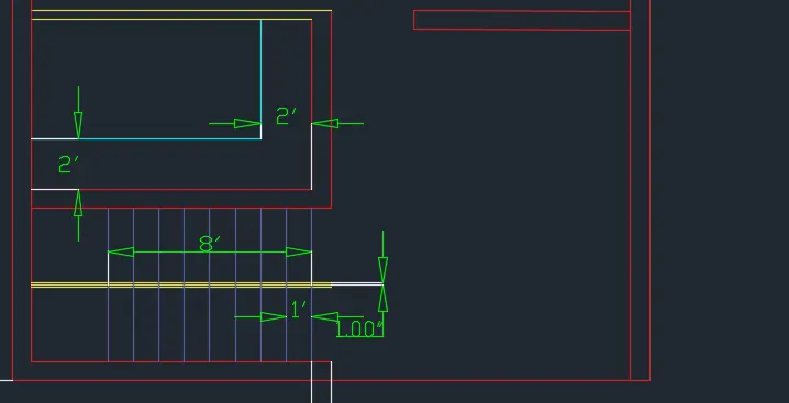
- Using the move tool, move the blue line in the image above 9" to the left.
- Select the same line and select Offset tool.
- Set 12" or 1' as offset distance.
- Select the Multiple to apply consecutive offsets of the given offset distance.
- Do the offset until you finish the 8th step
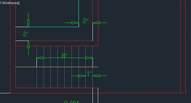
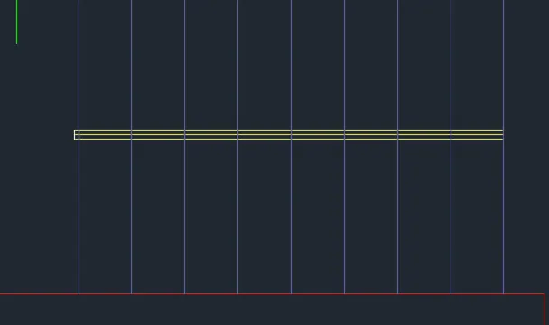
- Select the middle line and offset it 1" upward and downwards.
- Using the Trim tool, delete the vertical lines inside the horizontal lines.
- Using the line tool to enclose the the horizontal lines
- Move the left line 1" to the left and trim the horizontal lines on the left.
- Add an arrow at the middle of the stair to show its direction.
- To add the arrow, select the Leader tool.
- Select the Settings option.
- The Leader Settings window will appear.
- Click on "4" box to maintan the lines after the arrow.
- Select Ok.
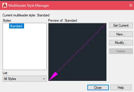
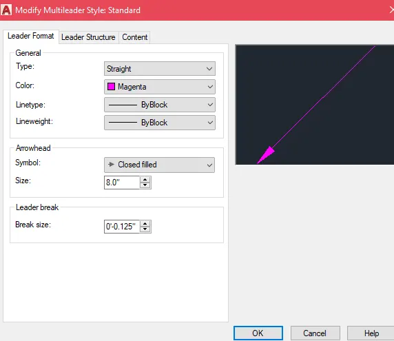
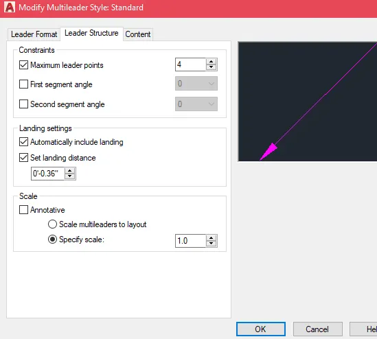
- Using the Line tool, connect the corner edges as shown below.
- Specify starting point as shown below and follow the position of the arrow.
- Make sure the Ortho Mode is on.
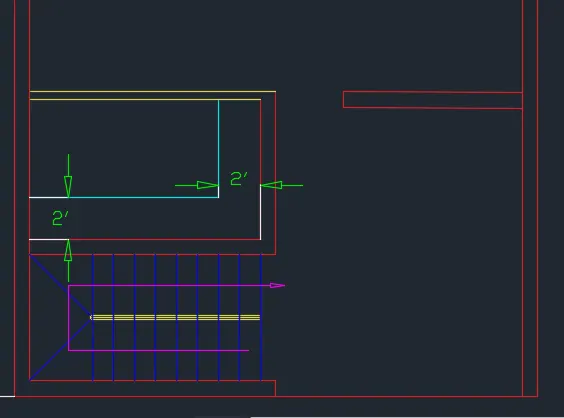
- Make the upper lines as hidden type. Select the line objects.
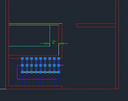
- Go to Properties on the Taskbar above and dragdown Linetype.
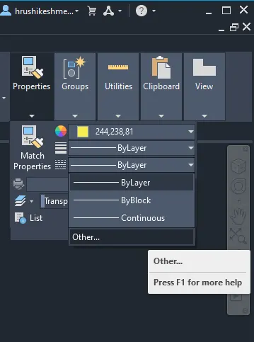
- Hear the Hidden Line is not yet loaded, click the "Other" option to open the "Linetype Manager" windo
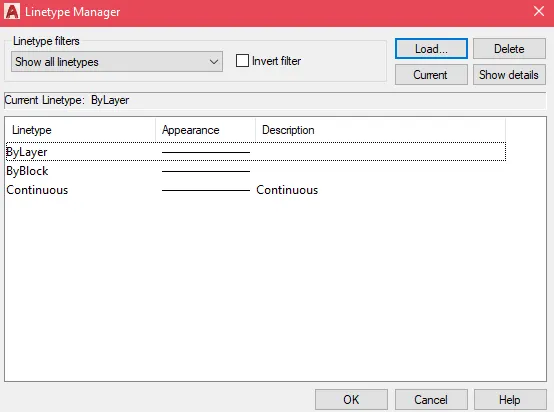
- Select "Load", the "Load or Reload Linetypes" window will appear. Search for the "Hidden" option in the selection and press Ok.
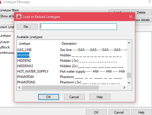
- Select the "Hidden" option as linetype of the selected line objects.
- Create the door symbols.
- To create the door symbols, follow the steps below.
Door Symbol Procedure
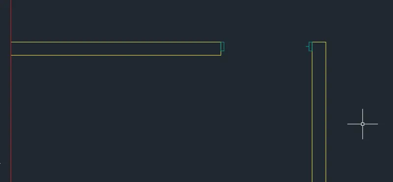
- On the corners of the opening, create a rectangle object with dimensions of 1" width and 3" length.
- Add the hinge symbol by adding a horizontal line in the center of either of the corners.
- The line length can be any length, for this sample we use 1".
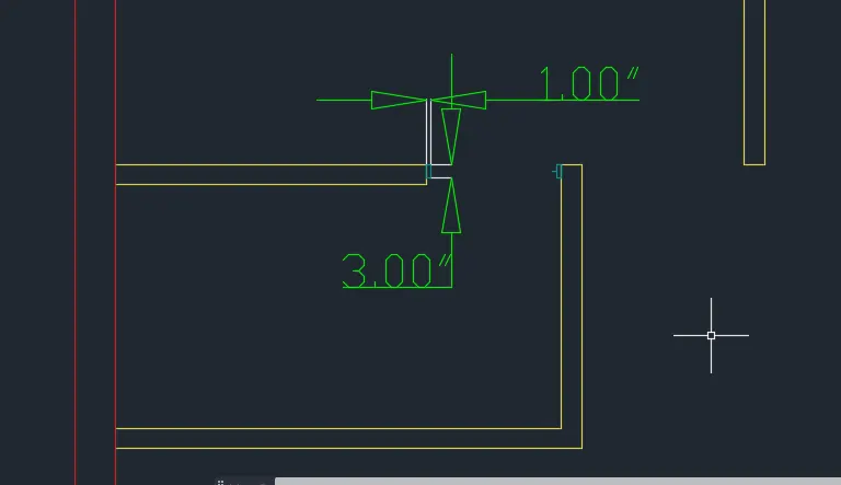
- Make a vertical line connecting from the horizontal line towards the direction of the door opening.
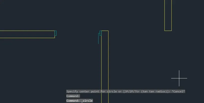
- Make a circle with the endpoint of the horizontal line as the center. Specify the radius of the circle as the midpoint of the rectangle on the opposite corner.
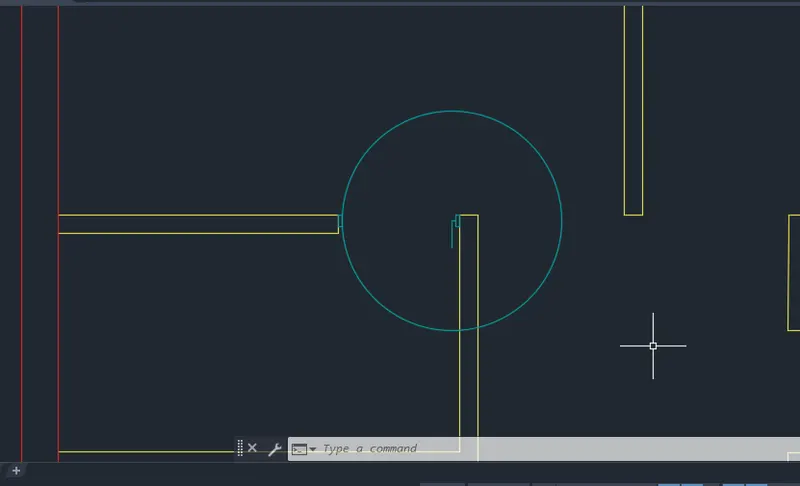
- Extend the vertical line to the circle and trim the outer edges to form the arc.
- Use the vertical line and rectangle object touching the circle as cutting edges
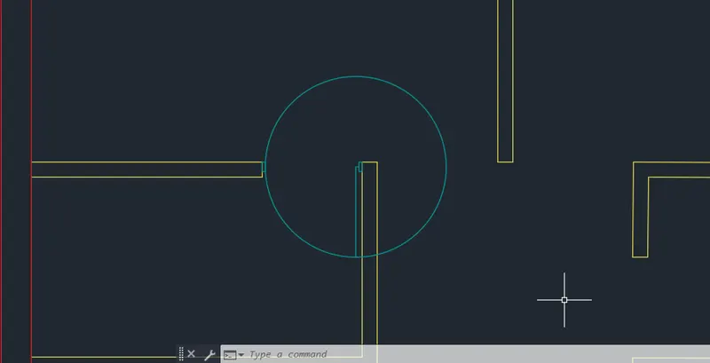
- Trim the unwanted person.
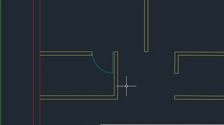
- Now do these steps to create all the door sizes.
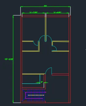
- Continue the sketch. Create the doors at specified locations.
- Create the Cabinet in Bedroom 1.
- Select Rectangle tool.
- First corner is the lower left corner of Bedroom 1.
- Rectangle dimensions are 5'-6" x 1'-6" (Approximate dimensions). Offset inward by 1" to create the cabinet boundaries.
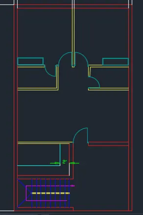
- Select both rectangles and copy it to the lower right corner of Bedroom 2.
- To copy the rectange, select the two rectangle objects. Select Copy tool.
- Specify base points as lower right of the rectangle.
- Specify second point as the lower right corner of Bedroom 2
- Create the window insede the wall separating the Parking area.
- To create the window, copy the small vertical line object of the Parking wall 1'-3" to the right.
- Select the created line object and copy it 6' to the right.
- To finish the window, select the line tool and connect the centers of the two created line objects.
- Now create the opening of the Kitchen. Select the right outer wall of the Kitchen and copy it 6'-4" to the left.
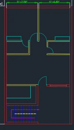
- Trim the unnecessary lines within the Outer walls.
- Select Trim tool and press enter to select all as cutting edges.
- Delete the unnecessary lines as shown below
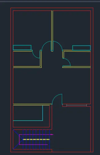
- Add the text using the Text tool. Select the Text tool and specify start point of text within the walls or in your desired location.
- Specify height of text as 6" or any desired height. You can always rescale the texts to any size using the Scale tool.
- The copy tool can also be used to multiply the text to other locations.
- Use the Dimlinear tool to add the dimensions at the desired locations.
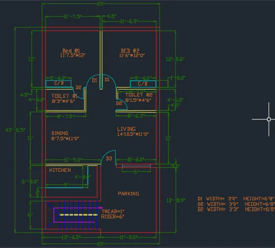
RESULT-:
B. SKETCH 2 – Seating Plan
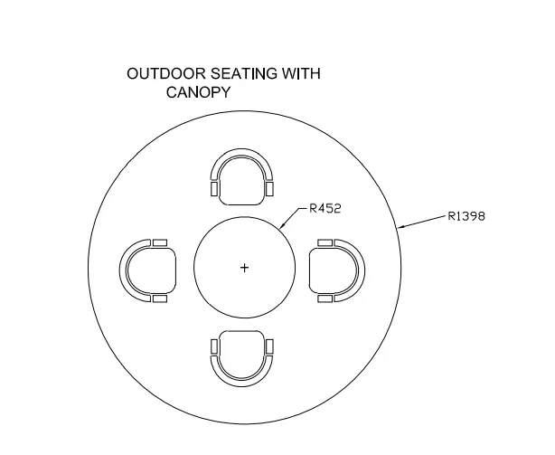
Challenge 2 - Sketch the seating plan for an outdoor canopy. Assume the dimensions for the seating. Also, consider the dimensions in mm.
PROCEDURE:
- The dimension used for the sketch of the Seat below are assumed.
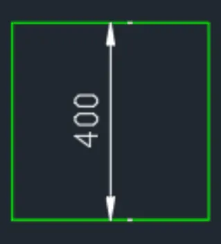
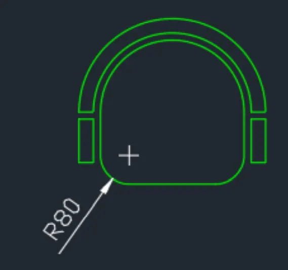
- Sketch the Seat. Select Rectangle tool and make a rectangle with 400 dimension
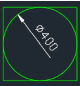
- Create a circle inside the rectangle with 400 units diameter.
- To create the circle, select the Circle tool.
- Specify center point of the circle as center of the rectangle.
- Select Diameter and specify the diameter as 400.
- Select the Trim tool.
- Press enter to select all as cutting edges.
- Delete the outer rectangle on top and the inner circle on the bottom.
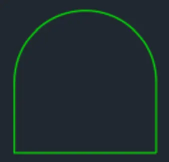
- Select the semi-circle object. Select Offset tool. Specify offset distance as 20 and click outside the object.
- Now select the created semi-circle object and using the same method, offset it by 40 units.
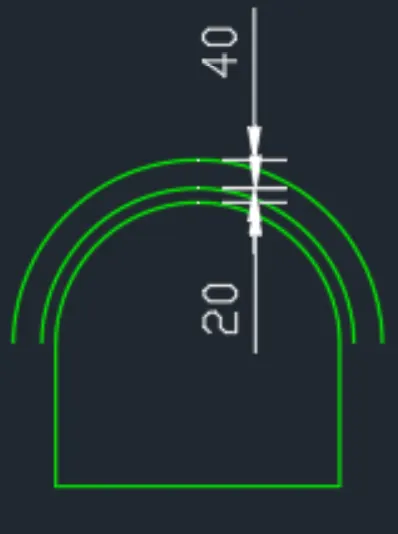
- Close the two outer semi-circle objects using the Line tool
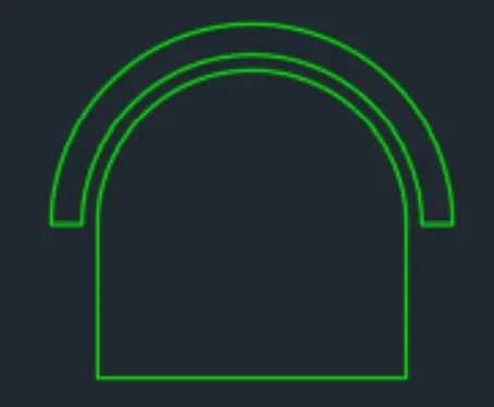
- Create a rectangular object on the lower left part of the semi-cicle object.
- Select the Rectangle tool.
- Specify the lower left point of the outer semi-circle as first corner point.
- Dimensions of the rectange are 40units width and 120units length.
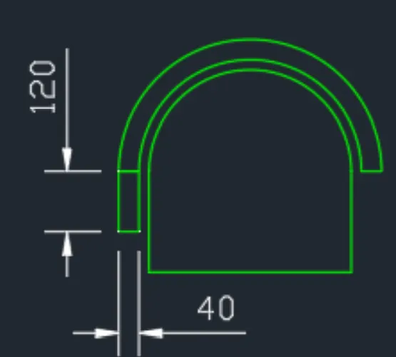
- Move the Rectangle object 20units downward.
- Select the Rectangle object.
- Select the Move tool and point downwards.
- Make sure Ortho Mode is turened on.
- Specify second point as 20units downward.
- After moving 20units downward, mirror the rectangle object with the mirror plane located vertically in the middle of the object.
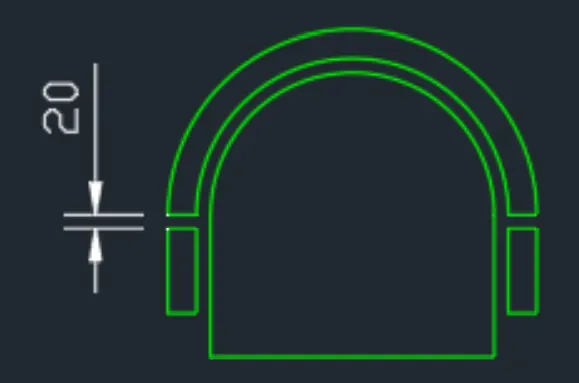
- Finish the sketch of the seat by doing a fillet on the lower corners of the rectangle. Select the Fillet tool.
- Specify radius of fillet as 80units.
- Fillet the lower corners of the rectangle
- Make the sketch of the seat as a Block.
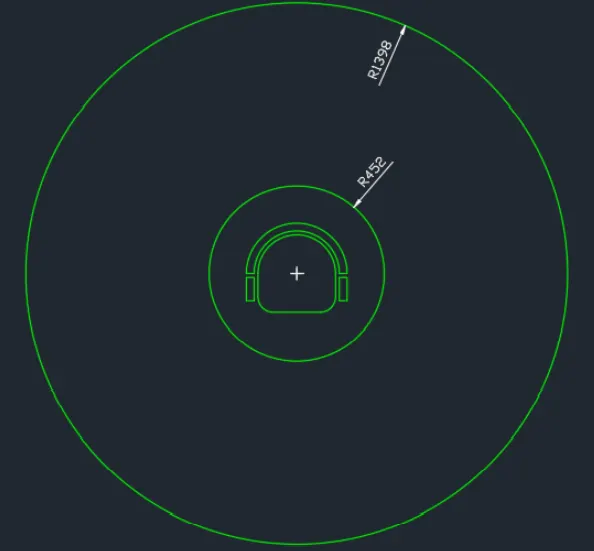
- Select the whole sketch. Use Ctrl+Shift+C command and specify the base point as the
Center of the sketch (Center point of the Semi-Circle). - Use Ctrl+Shift+V to past the object as a Block.
- Using the center of the block as the center of the sketch, create a circle with 452units of diameter and 1398units of diameter.
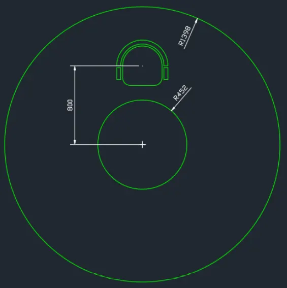
- Move the block 800units upward
- Select the block object.
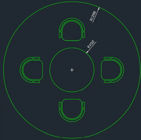
- Select the Array tool.
- Select Polar settings.
- Specify center of array as the center of the sketch (Center of the circle).
- Select Items option.
- Enter number of items as 4.
- Continue pressing enter to end the command.
- Use Dimradius command to identify the radius of the circle.
RESULT-:
C. SKETCH 3 – Toilet and Utility Room Plan
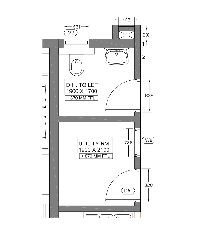
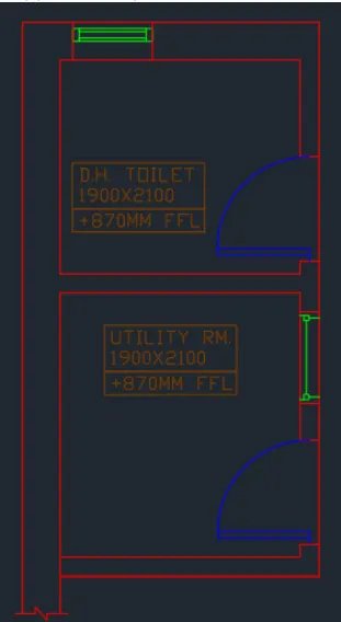
Challenge 3 - Sketch the part plan for the toilers and utilities room. Consider the outer wall thickness as 300mm and inner wall thickness as 150mm. Also, assume the missing dimension, Texts, dimensions, and hatches are only for references. Also, symbols for toilets and w/c are also for references.
PROCEDURE:
- Create the boundary elements.
- Select the Rectangle tool.
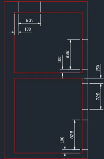
- Create a rectangle with dimensions of 1900x1700 units and 1900x2100 units spaced at 150units vertically.
- This will specify the inner dimensions of the toilet and utility area
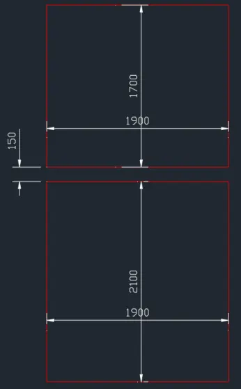
- Select the two rectangles and apply the Explode command to seperate the line objects.
- Offset the upper and left line by 300units while the right and lower line by 150units
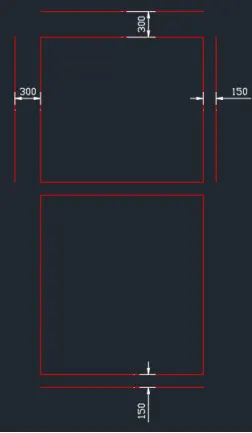
- Use the fillet command with radius 0 to enclose the lines
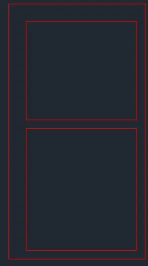
- Create the boundary elements for the door and window openings.
- Using the Line tool, create a line object at each corner of the openings.
- Use the Move tool and Copy tool to create the lines specified below.
- Select the trim tool.
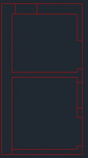
- Press enter to select all as cutting edges.
- Delete the unnecessary lines as shown below.
- Create the window on the upper opening.
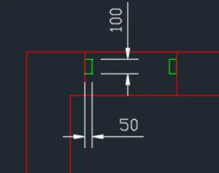
- Select Rectangle tool and create a rectangle with dimensions of 50x100units.
- Specify the first corner of rectangle as midpoint of the line enclosing the opening.
- Use Copy tool to create the rectangle object on the other side.
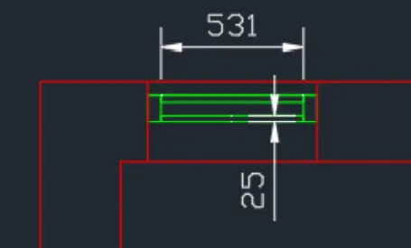
- Create another rectangle using the Rectangle tool with 531units width and 25units length with the upper corner of the created rectangle as first corner points.
- Copy the rectangle to the lower corner to finish the window.
- Create the window on the right side.
- Select the Rectangle tool and create a rectangle with dimension of 40x40units.
- Move the rectangle object 30units to the right and 30units below.
- Using the Line tool, create a line connecting the upper corner of the rectangle horizontally to the left line of the opening boundary.
- Create another line using the the midpoint of the right line of the rectangle as first points connecting perpendicularly to the right line of the opening boundary
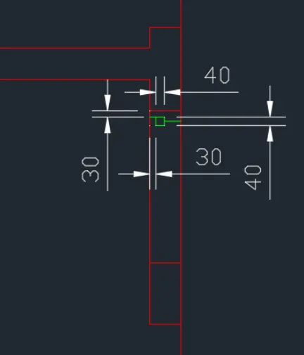
- Mirror the created objects on the other side of the opening boundary.
- Use the center plane of the opening boundary horizontally as the mirror plane.
- When the mirrored object is created, connect the center points of the rectangle object using the Line tool.
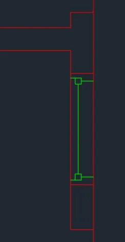
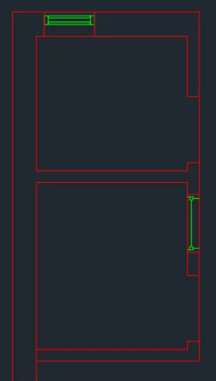
- The windows created is as shown below
- Create the door for the Utility room.
- Create a line using the Line tool.
- Specify first points as the center of the lower line of the opening boundary with the Line length as 100units.
- At the upper endpoint of the created line, make a horizontal line object with any length.
- Copy this line by 50units downward
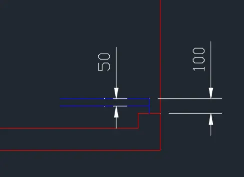
- Create a circle object using the Circle tool with the endpoint of the vertical line as the center point.
- When specifying the radius of the circle, click on the midpoint of the upper line of the opening boundary.
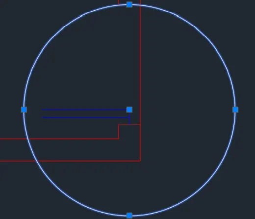
- Extend the upper horizontal line to the edge of the circle object.
- Afterwards, trim the outer portion of the circle using the upper line of the opening boundary and the extended horizontal line as cutting edges.
- To continue, make a line object using the endpoint of the extended horizantal line as first point with any length vertically pointed downwards.
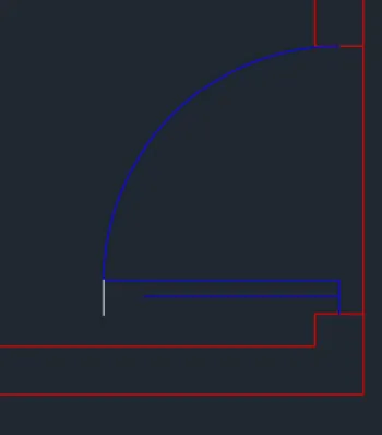
- Use the fillet tool to enclose the corners of the door. Fillet radius should be 0
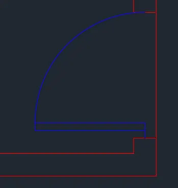
- Do the same procedure to create the door for the Toilet Area.
- Once finished, the doors and windows will show as below.
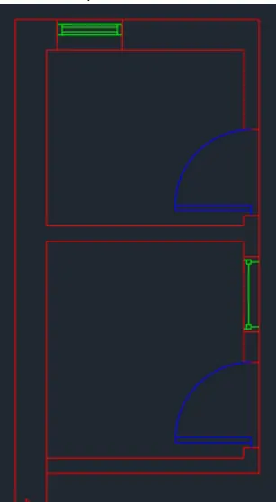
- Create the text object to identify the areas.
- Select Text tool specifying any points within the area as starting point.
- Specify text height as 100units and rotation angle as 0.
- You can enclose the texts using the Rectangle and Line tool.
- You can also use the Copy tool to duplicate the texts
- Create the upper right part.
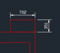
- Select Rectangle tool and specify the upper outside corner as first corner point.
- Create a rectangle object with 702x351 units dimensions.
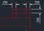
- Explode the object. Offset/Copy the outer lines inward by 150units
- Use the Trim tool to delete the unnecessary lines.
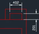
- Objects inside the Toilet Area are for reference only.
- Procedures for these objects will not be provided.
- Add the dimensions using the Dimlinear tool and finish the Sketch.
Result:
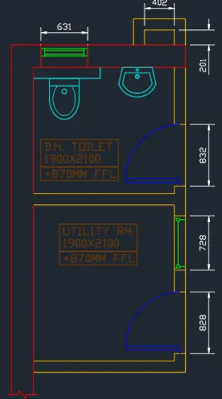
- The AutoCAD software can be adapted and used in the Civil Engineering industry. We can conclude that with in depth knowledge of the AutoCAD tools as well as the know-how on their applicable combinations will make easier and faster sketches for related documents.
- An example is a full residential house blueprint. This includes floor plan and detailed drawings needed and specified in the a given project.
- By combining the shown AutoCAD tools, especially the Copy, Move, Rectangle, Circular, Trim, Extend, and Fillet tool, sketches in the Civil Engineering Industry can be provided with complete details.
- Tools like Text and Dimensions are also a significant part of these software to provide specific details in the sketch.
- Aside from these, the Layer Tool is also a big part of the AutoCAD software where the objects can be grouped and controlled within a specific window. These will provide organization within the sketch.
- In completing this challenge, the application of the AutoCAD software in Civil related documents is made clear.