Creation of geometries by Coordinate system methods using AutoCad
Q.Create the geometries from P1 to P2 using all the coordinates system methods. You need to use the Line tool to create the geometries. Where required you need to use the circle tool.
Please read the drawings and find out the missing dimensions before working on the sketches.
AIM:
- Create the geometries from P1 to P2 using all the coordinates system methods. And we need to use line tool, circle tube if required and find the missing dimensions.
Introduction:
- AutoCAD was derived from a program that began in 1977, and then released in 1979 called InterCAd, also referred to in early Autodesk documents as MicroCAD, which was written prior to Autodesk's (then marinchip software partners) formation by Autodesk cofounder Michael Riddle.
- The first version by Autodesk was demonstrated at the 1982 Comdex and released that Decmber. AutodCAD supported CP/M-80 computers. As Autodesk's foagship product, be March 1986 AutoCAD had become the most ubiquitous CAD program worldwide The fundamental purpose of AutoCAD is to creat lines, arcs, circle and other geometric shapes that are necessary for the drawing that are free from errrors.
- Different Coordinate systems used are: In Autocad there are two coordinate systems: Cartesian and polar.To these coordinate systems the absolute and relative coordinates of Autocad as are applicable.
- Coordinate Systems: Coordinate system is a system where numbers are used to determine the unique position of points and/or other geometric elements.Also coordinates in AutoCAD can be set by mouse, input the values of coordinates in the command line and enter coordinates using dynamic input.
There are three types of co-ordinate systems
1.Absolute coordinate systems
2.Relative coordinate systems
- Relative rectangular coordinates
- Relative polar coordinates
3.Direct distance entry
1. Absolute Coordinate System:
- In this system all points are established at some distance in the x & y-axis (sometimes z-axis) from a common origin (usually 0,0).
2. Relative Coordinate System:
- The location of a Relative coordinate is defined by its distance from a reference point. In AutoCAD, when using this system the first point of the drawing/geometry is always absolute, i.e. it is established with respect to origin (0.0) and then all the successive positions are established with respect to their preceding point.
- This system is further classified as
- (a)Relative rectangular coordinates system
- (b)Relative polar coordinates system
(a)Relative rectangular coordinates system:
- It is a coordinate system that specifies each point by a pair of numerical coordinates in the x-axis and y-axis. In this system the points succeeding the first point are typed in as '@x,y' in the command line.
(b)Relative polar coordinates system:
- This system specifies the distance (length) and angle of a particular point with respect to its previous point. In Relative polar coordinate system, points are established by typing @distance
Procedure:
- Click on AutoCAD application and open this application
- Initially set the template Imperial (Feet and inches)and Units(Decimal)
- Type startup in teh command line and then insert the values 1.
- Then go to application menu -->select new-->creat drawing
- Select default setting as Imperial (feet and inches)
- In default setting click on use a wizard and in that advance of setting and unit as decimal and precision as 0
- Set Angle as Decimal Degree and precision as 0 and click next
- Set Angle Measure as EAST and Next
- Set Angle Direction as Counter-Clockwise and click Next
- Set Area by provideing Lengh as 10 and Width as 10
- Finished
- For Eg. :To draw a line: {always follw the command while drawing a line.}
- Ribbon-->Home-->Draw panel-->Line.
- Menu bar-->Draw-->Line.
- Coomand-->Enter line or 'L'
- Commands used:
1. Line command
2. Dimlinear command
3. Text command
4. Circle command
1.Create the geometries for P1 using all the coordinates system methods
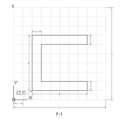
{a} Absolute cooardinate system:
Procedure:
- Select line tool from the ribbon tab/ write line in comand box, it will show "specify the first point"
- Now,Enter the first point as (2,1).
- Next, The command ask to enter next point.
- Specify the next point as ( 8,1 )
- Specify the next point as ( 8,2 )
- Specify the next point as ( 3,2 )
- Specify the next point as ( 3,6 )
- Specify the next point as ( 8,6 )
- Specify the next point as ( 8,7 )
- Specify the next point as ( 2,7 )
- Specify the next point as ( 2,1 ), else click on the close in commond prompt.
- The geometry is done.
Result:
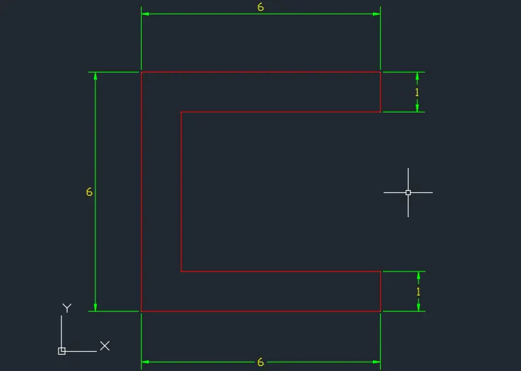
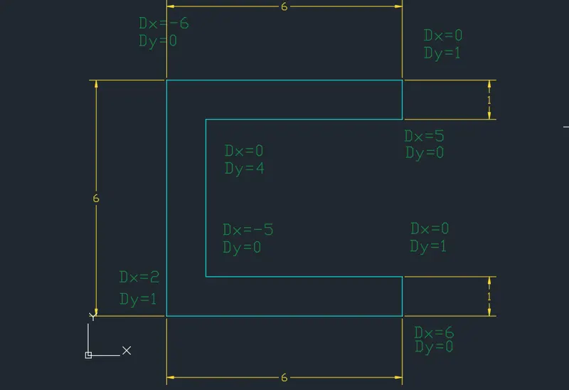
{b} Relative Rectangular coordinate systemi.
Procedure:
- Select the Line tool by entering 'LINE' command in the command tab.
- Specify the starting coordinate of point 1 as 2,1 in the command line.
- Specify the next coordinate of point 2 as @6,0 in the command line.
- Specify the next coordinate of point 3 as @0,1 in the command line.
- Specify the next coordinate of point 4 as @-5,0 in the command line.
- Specify the next coordinate of point 5 as @0,4 in the command line.
- Specify the next coordinate of point 6 as @5,0 in the command line.
- Specify the next coordinate of point 7 as @0,1 in the command line.
- Specify the next coordinate of point 8 as @-6,0 in the command line.
- Click 'Close' on the command line.
- The geometry is done.
Result :
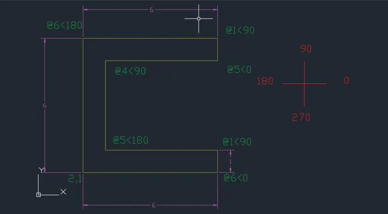
{c} Relative Polar coordinate system
Procedure:
- Select the Line tool by entering 'LINE' command in the command tab.
- Specify the starting coordinate of point 1 as 2,1 (Starting Point)in the command line.
- Specify the next coordinate of point 2 as @6<0 (Towards East) in the command line.
- Specify the next coordinate of point 3 as @1<90 (Towards North) in the command line.
- Specify the next coordinate of point 4 as @5<180 (Towards West) in the command line.
- Specify the next coordinate of point 5 as @4<90 (Towards North) in the command line.
- Specify the next coordinate of point 6 as @5<0 (Towards East) in the command line.
- Specify the next coordinate of point 7 as @1<90 (Towards North) in the command line.
- Specify the next coordinate of point 8 as @6<180 (Towards west) in the command line.
- Click 'Close' on the command line.
- The geometry is done.
Result :
{d} Direct Distance Entry method
Procedure:
- Select the Line tool by entering 'LINE' command in the command tab.
- Specify the starting coordinate of point 1 as 2,1 in the command line.
- Enter the length of point 2 as 6 in the command line towards +ve x-axis.
- Enter the length of point 3 as 1 in the command line towards +ve y-axis.
- Enter the length of point 4 as 5 in the command line towards -ve x-axis.
- Enter the length of point 5 as 4 in the command line towards +ve y-axis.
- Enter the length of point 6 as 5 in the command line towards +ve x-axis.
- Enter the length of point 7 as 1 in the command line towards +ve y-axis.
- Enter the length of point 8 as 6 in the command line towards -ve x-axis.
- Click 'Close' on the command line.
- The geometry is done.
Result :
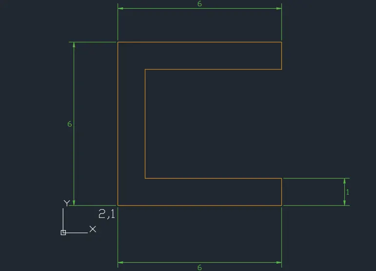
Introduction:
Create the geometries for P2 using all the coordinates system methods.
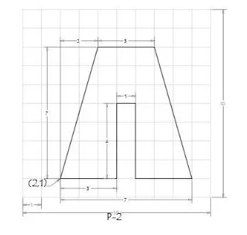
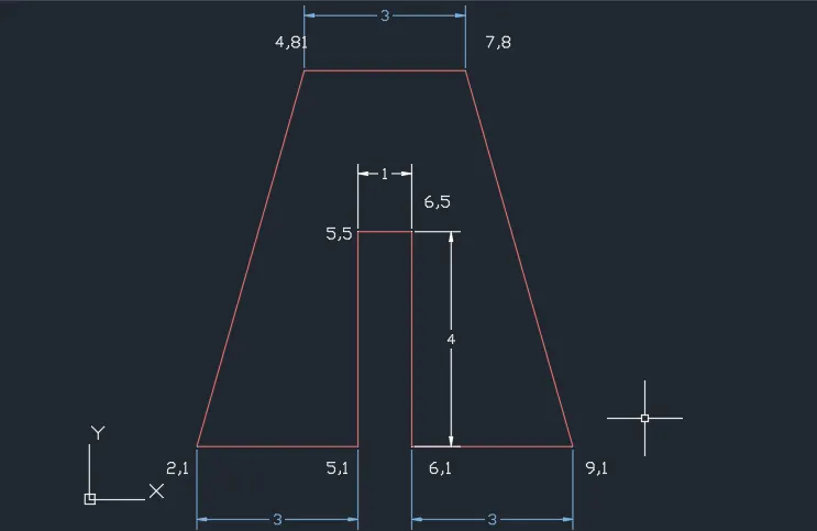
{a} Using Absolute coordinate system
Procedure:
- Select the Line tool by entering 'LINE' command in the command tab.
- Specify the starting coordinate of point 1 as 2,1 in the command line.
- Specify the next coordinate of point 2 as 5,1 in the command line.
- Specify the next coordinate of point 3 as 5,5 in the command line.
- Specify the next coordinate of point 4 as 6,5 in the command line.
- Specify the next coordinate of point 5 as 6,1 in the command line.
- Specify the next coordinate of point 6 as 9,1 in the command line.
- Specify the next coordinate of point 7 as 7,8 in the command line.
- Specify the next coordinate of point 8 as 4,8 in the command line.
- Click 'Close' on the command line.
Result :
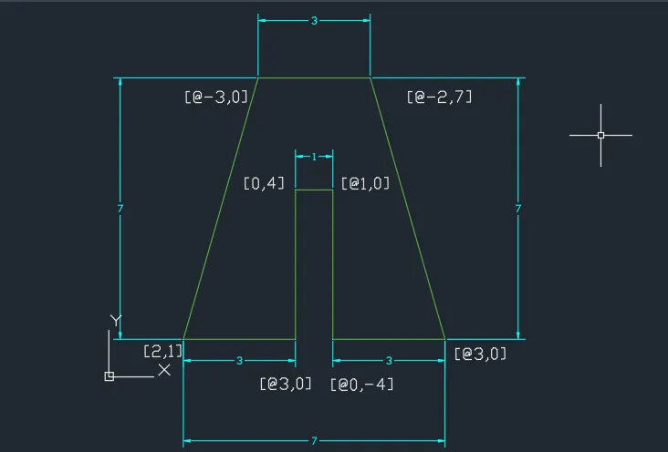
{b} Relative Rectagular coordinate systems
Procedure:
- Select the Line tool by entering 'LINE' command in the command tab.
- Specify the starting coordinate of point 1 as 2,1 in the command line.
- Specify the next coordinate of point 2 as @3,0 in the command line.
- Specify the next coordinate of point 3 as @0,4 in the command line.
- Specify the next coordinate of point 4 as @1,0 in the command line.
- Specify the next coordinate of point 5 as @0,-4 in the command line.
- Specify the next coordinate of point 6 as @3,0 in the command line.
- Specify the next coordinate of point 7 as @-2,7 in the command line.
- Specify the next coordinate of point 8 as @-3,0 in the command line.
- Click 'Close' on the command line.
Result :
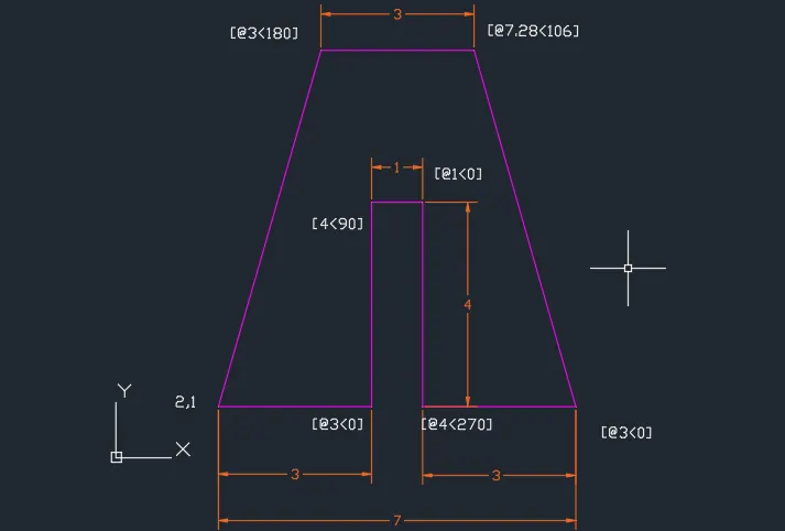
{c} Using Relative Polar coordinate system
Procedure:
- Select the Line tool by entering 'LINE' command in the command tab.
- Specify the starting coordinate of point 1 as 2,1 in the command line.
- Specify the next coordinate of point 2 as @3<0 in the command line.
- Specify the next coordinate of point 3 as @4<90 in the command line.
- Specify the next coordinate of point 4 as @1<0 in the command line.
- Specify the next coordinate of point 5 as @4<270 in the command line.
- Specify the next coordinate of point 6 as @3<0 in the command line.
- Specify the next coordinate of point 7 as @7.28<105.9 in the command line.
- Specify the next coordinate of point 8 as @3<180 in the command line.
- Click 'Close' on the command line.
Result :
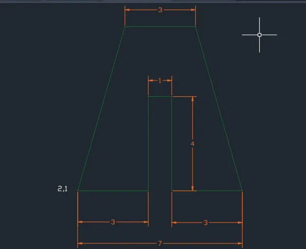
{d} Direct Distance Entry method
Procedure:
- Select the Line tool by entering 'LINE' command in the command tab.
- Specify the starting coordinate of point 1 as 2,1 in the command line.
- Enter the length of point 2 as 3 in the command line towards +ve x-axis.
- Enter the length of point 3 as 4 in the command line towards +ve y-axis.
- Enter the length of point 4 as 1 in the command line towards +ve x-axis.
- Enter the length of point 5 as 4 in the command line towards -ve y-axis.
- Enter the length of point 6 as 3 in the command line towards +ve x-axis.
- Enter the length of point 7 as 7.28 in the command line at an angle of <105.9 from +ve x-direction while keeping polar tracking on.
- Enter the length of point 8 as 3 in the command line towards -ve x-axis.
- Click 'Close' on the command line
Result :
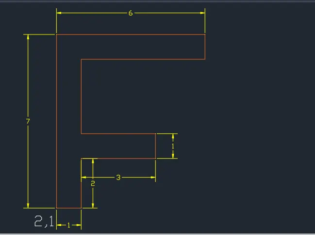
Create the geometries from P3 to P10 using any coordinates system methods.
P3: Steps for creating the geometry in P-3 using Absolute coordinate system
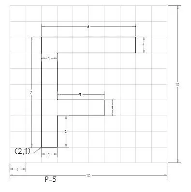
Procedure:
- Select the Line tool by entering 'LINE' command in the command tab.
- Specify the starting coordinate of point 1 as 2,1 in the command line.
- Specify the next coordinate of point 2 as 3,1 in the command line.
- Specify the next coordinate of point 3 as 3,3 in the command line.
- Specify the next coordinate of point 4 as 6,3 in the command line.
- Specify the next coordinate of point 5 as 6,4 in the command line.
- Specify the next coordinate of point 6 as 3,4 in the command line.
- Specify the next coordinate of point 7 as 3,7 in the command line.
- Specify the next coordinate of point 8 as 8,7 in the command line.
- Specify the next coordinate of point 9 as 8,8 in the command line.
- Specify the next coordinate of point 10 as 2,8 in the command line.
- Click 'Close' on the command line.
Result:
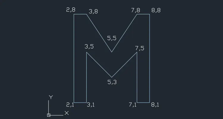
P-4 : Steps for creating the geometry in P-4 using Absolute coordinate system
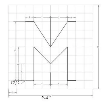
Procedure:
- Select the Line tool by entering 'LINE' command in the command tab.
- Specify the starting coordinate of point 1 as 2,1 in the command line.
- Specify the next coordinate of point 2 as 3,1 in the command line.
- Specify the next coordinate of point 3 as 3,5 in the command line.
- Specify the next coordinate of point 4 as 5,3 in the command line.
- Specify the next coordinate of point 5 as 7,5 in the command line.
- Specify the next coordinate of point 6 as 7,1 in the command line.
- Specify the next coordinate of point 7 as 8,1 in the command line.
- Specify the next coordinate of point 8 as 8,8 in the command line.
- Specify the next coordinate of point 9 as 7,8 in the command line.
- Specify the next coordinate of point 10 as 5,5 in the command line.
- Specify the next coordinate of point 11 as 3,8 in the command line.
- Specify the next coordinate of point 12 as 2,8 in the command line.
- Click 'Close' on the command line.
Result:
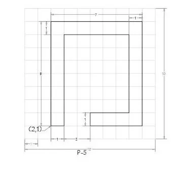
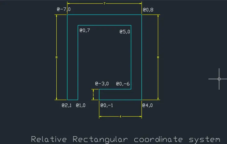
P-5 :Steps for creating the geometry in P-5 using Relative Rectangular coordinate system
Procedure:
- Select the Line tool by entering 'LINE' command in the command tab.
- Specify the starting coordinate of point 1 as 2,1 in the command line.
- Specify the next coordinate of point 2 as @1,0 in the command line.
- Specify the next coordinate of point 3 as @0,7 in the command line.
- Specify the next coordinate of point 4 as @5,0 in the command line.
- Specify the next coordinate of point 5 as @0,-6 in the command line.
- Specify the next coordinate of point 6 as@-3,0 in the command line.
- Specify the next coordinate of point 7 as @0,-1 in the command line.
- Specify the next coordinate of point 8 as @4,0 in the command line.
- Specify the next coordinate of point 9 as @0,8 in the command line.
- Specify the next coordinate of point 10 as @-7,0 in the command line.
- Click 'Close' on the command line.
Result:
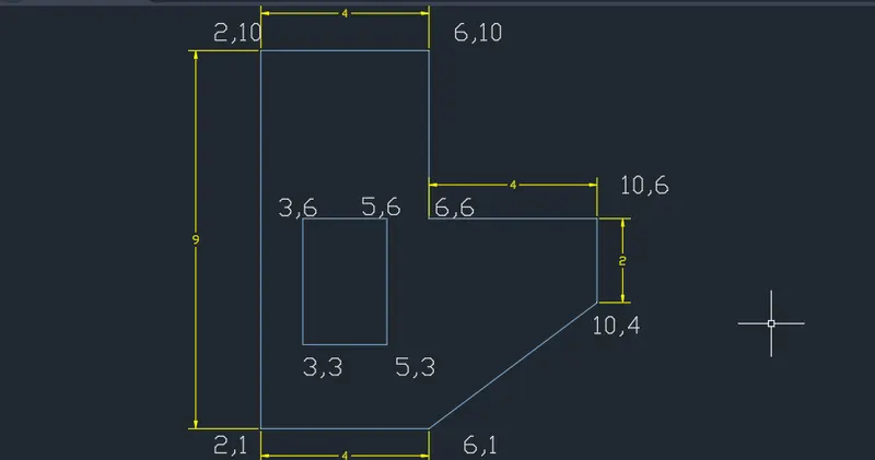
P-6: Steps for creating the geometry in P-6 using Absolute coordinate system
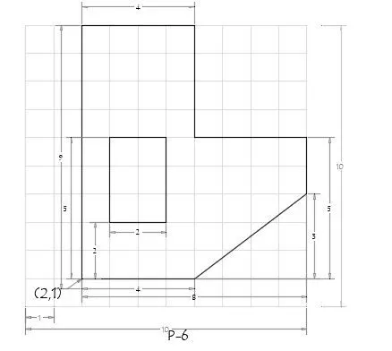
Procedure:
- Select the Line tool by entering 'LINE' command in the command tab.
- Specify the starting coordinate of point 1 as 2,1 in the command line.
- Specify the next coordinate of point 2 as 6,1 in the command line.
- Specify the next coordinate of point 3 as 10,4 in the command line.
- Specify the next coordinate of point 4 as 10,6 in the command line.
- Specify the next coordinate of point 5 as 6,6 in the command line.
- Specify the next coordinate of point 6 as 6,10 in the command line.
- Specify the next coordinate of point 7 as 2,10 in the command line.
- Click 'Close' on the command line.
- Specify the next coordinate of point 8 as 3,3 in the command line.
- Specify the next coordinate of point 9 as 5,3 in the command line.
- Specify the next coordinate of point 10 as 5,6 in the command line.
- Specify the next coordinate of point 11 as 3,6 in the command line.
- Click 'Close' on the command line.
Result:
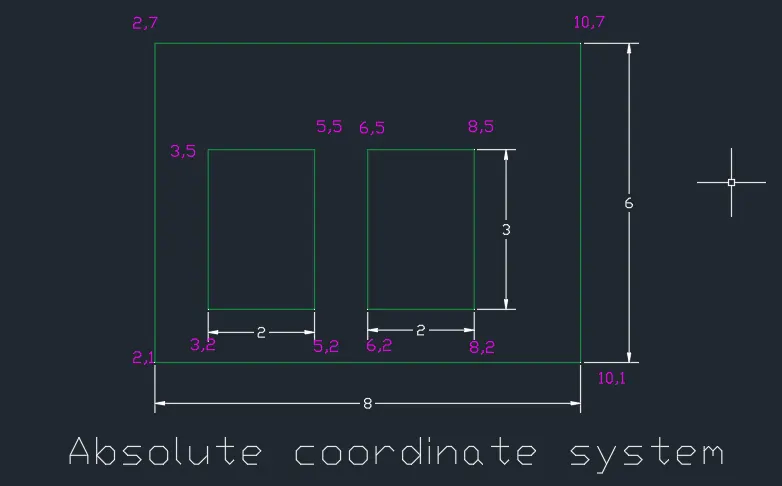
P-7 : Steps for creating the geometry in P-7 using Absolute coordinate system
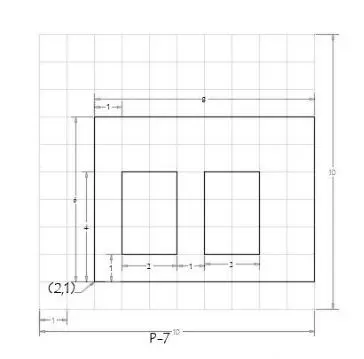
Procedure:
- Select the Line tool by entering 'LINE command in the command tab
- Specify the starting coordinate of point 1 as 2,1 in the command line.
- Specify the next coordinate of point 2 as 10,1 in the command lineiv.
- Specify the next coordinate of point 3 as 10,7 in the command line.
- Specify the next coordinate of point 4 as 2,7 in the command line.
- Click 'Close' on the command line.
- Select the Line tool by entering 'LINE command in the command tab.
- Specify the next coordinate of point 5 as 3.2 in the command line
- Specify the next coordinate of point 6 as 5.2 in the command line
- Specify the next coordinate of point 7 as 5.5 in the command line.
- Specify the next coordinate of point 8 as 3.5 in the command line.
- Click 'Close' on the command line.
- Select the Line tool by entering LINE command in the command tab
- Specify the next coordinate of point 9 as 6.2 in the command line.
- Specify the next coordinate of point 10 as 8.2 in the command line.
- Specify the next coordinate of point 11 as 8.5 in the command line
- Specify the next coordinate of point 12 as 6,5 in the command line
- Click Close' on the command line
Result:
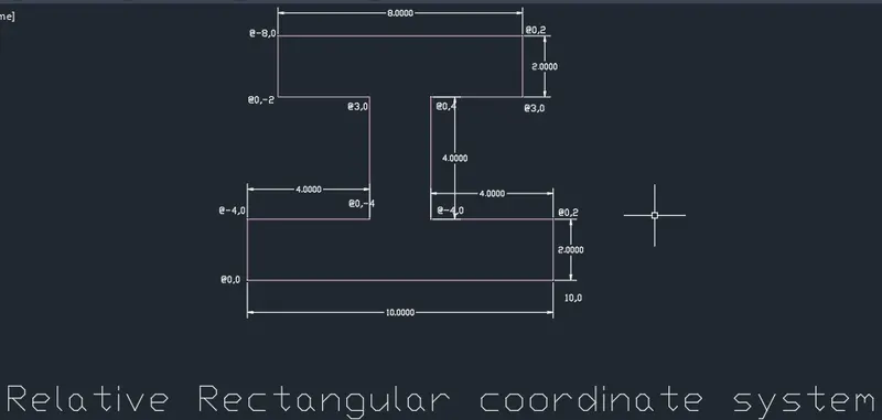
P-8 : Steps for creating the geometry in P-8 using Relative Rectangular coordinate system
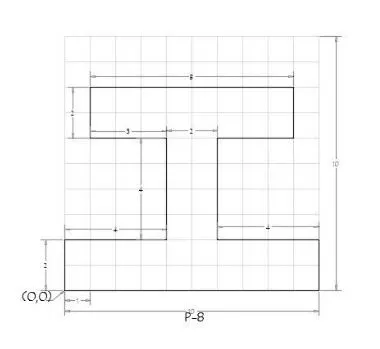
Procedure:
- Select the Line tool by entering 'LINE' command in the command tab.
- Specify the starting coordinate of point 1 as 0,0 in the command line.
- Specify the next coordinate of point 2 as @10,0 in the command line.
- Specify the next coordinate of point 3 as @0,2 in the command line.
- Specify the next coordinate of point 4 as @-4,0 in the command line.
- Specify the next coordinate of point 5 as @0,4 in the command line.
- Specify the next coordinate of point 6 as 3,0 in the command line.
- Specify the next coordinate of point 7 as @0,2 in the command line.
- Specify the next coordinate of point 8 as @-8,0 in the command line.
- Specify the next coordinate of point 9 as @0,-2 in the command line.
- Specify the next coordinate of point 10 as @3,0 in the command line.
- Specify the next coordinate of point 11 as @0.-4 in the command line.
- Specify the next coordinate of point 12 as @-4,0 in the command line.
- Click 'Close' on the command line.
Result:
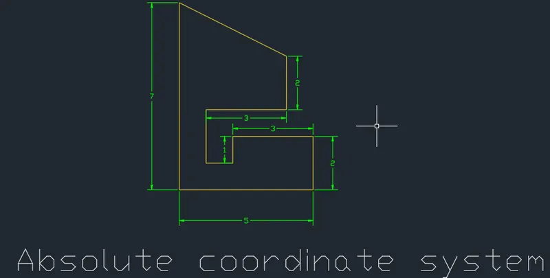
P-9 : Steps for creating the geometry in P-9 using Absolute coordinate system
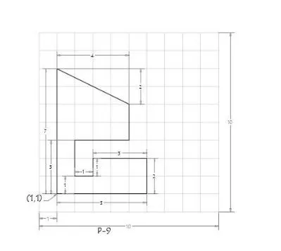
Procedure:
- Select the Line tool by entering 'LINE' command in the command tab.
- Specify the starting coordinate of point 1 as 1,1 in the command line.
- Specify the next coordinate of point 2 as 6,1 in the command line.
- Specify the next coordinate of point 3 as 6,3 in the command line.
- Specify the next coordinate of point 4 as 3,3 in the command line.
- Specify the next coordinate of point 5 as 3,2 in the command line.
- Specify the next coordinate of point 6 as 2,2 in the command line.
- Specify the next coordinate of point 7 as 2,4 in the command line.
- Specify the next coordinate of point 8 as 5,4 in the command line.
- Specify the next coordinate of point 9 as 5,6 in the command line.
- Specify the next coordinate of point 10 as 1,8 in the command line.
- Click 'Close' on the command line.
Result:
P-10 : Steps for creating the geometry in P-10 using Relative Polar coordinate system
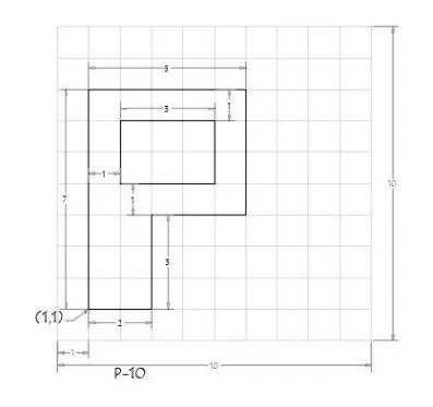
Procedure:
- Select the Line tool by entering 'LINE' command in the command tab.
- Specify the starting coordinate of point 1 as 1,1 in the command line.
- Specify the next coordinate of point 2 as @2<0 in the command line.
- Specify the next coordinate of point 3 as @3<90 in the command line.
- Specify the next coordinate of point 4 as @3<0 in the command line.
- Specify the next coordinate of point 5 as @4<90 in the command line.
- Specify the next coordinate of point 6 as @5<180 in the command line.
- Click 'Close' on the command line.
- Select the Line tool by entering 'LINE' command in the command tab.
- Specify the next coordinate of point 7 as 2,5 in the command line.
- Specify the next coordinate of point 8 as @3<0 in the command line.
- Specify the next coordinate of point 9 as @2<90 in the command line.
- Specify the next coordinate of point 10 as @3<180 in the command line.
- Click 'Close' on the command line.
Result:
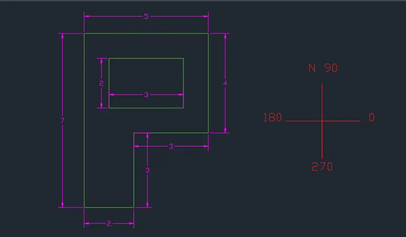
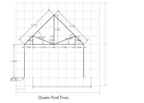
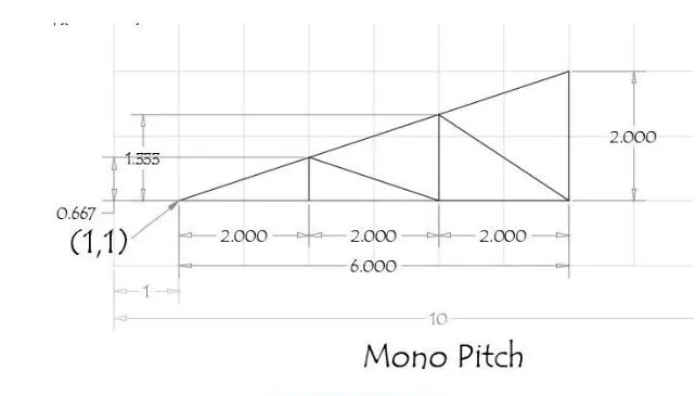
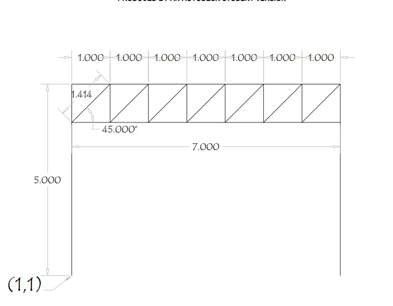
Draw the profile and the trusses using any coordinate system methods. The dimensions are there for references.
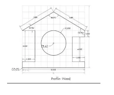
[1.] AIM: Draw the profile and the wood using any coordinate system methods.
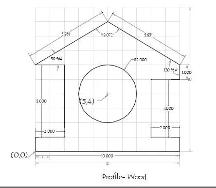
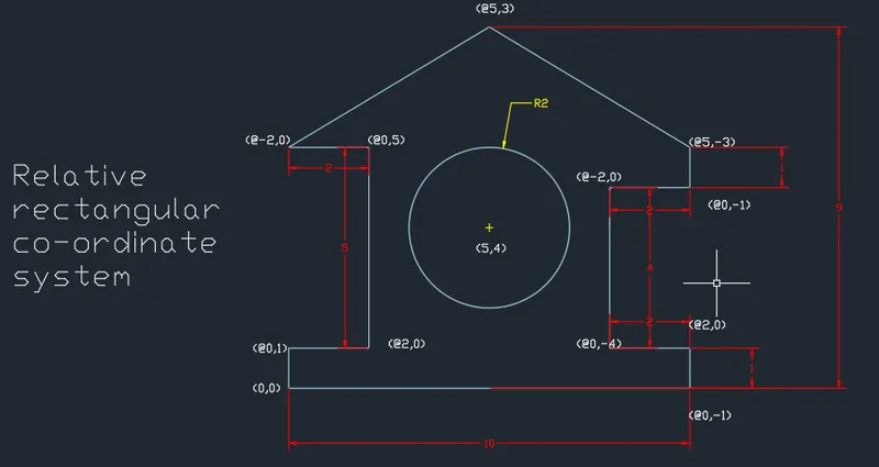
Procedure:Using Relative rectangular co-ordinate system
- Choose the line tool.
- Type absolute coordinates of start point 0,0 in command box and press enter.
- Then type or specify next point as @0,1 in command box and press enter
- Then type next point as @2,0 in command box and press enter.
- Then type next point as @0,5 in command box and press enter.
- Then type next point as @-2,0 in command box and press enter.
- Then type next point as @5,3 in command box and press enter.
- Then type next point as @5,-3 in command box and press enter.
- Then type next point as @0,-1 in command box and press enter.
- Then type next point as @-2,0 in command box and press enter.
- Then type next point as @0,-4in command box and press enter.
- Then type next point as @2,0 in command box and press ente
- Then type next point as @0,-1 in command box and press enter.
- Then type next point as @-10,0 in command box and press enter button or click on close option in command box
- Type C or CIRCLE in the command box and press enter.
- Then specify or type the center point coordinate of circle as 5,4 in command box and press enter.
- Then specify radius of circle as 2 in the command box and press enter.
Result:
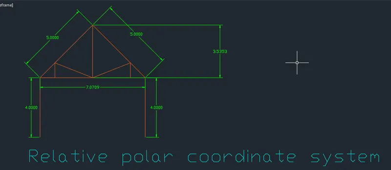
[2.] AIM:Drawing the Queen Post Truss using Relative polar coordinate system method
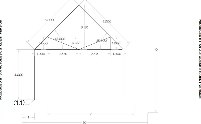
Procedure :
- Choose the line command.
- Specify the start point 1,1 in the command box and press enter.
- Type the next point as @4<90 in command box and press enter.
- Type the next point as @5<45 in command box and press enter.
- Type the next point as @5<315 in command box and press enter.
- Type the next point as @4<270 in command box and press enter twice.
- Choose the line tool and specify first point as 1,5 in command box and press enter.
- Specify the next point and type @7.072<0 in command box and press enter twice.
- Choose the line tool and specify first point as 2,5 in command box and press enter.
- Specify the next point @1<90 in the command box and press enter.
- Then specify next point @2.726<338.480 in command box and press enter.
- Then specify next point @2.726<21.520 in command box and press enter.
- Specify next point @1<270 in command box and press enter twice.
- Again, choose line tool and specify the point 4.536,5 in command box and press enter.
- Specify next point as @3.536<90 in command box and press double enter.
Result:
[3.] AIM:Drawing the Mono Pitch Absolute coordinate system method
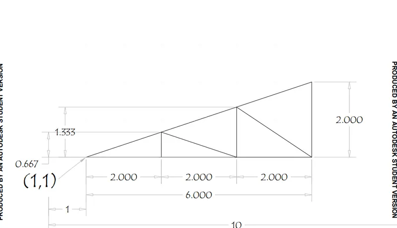
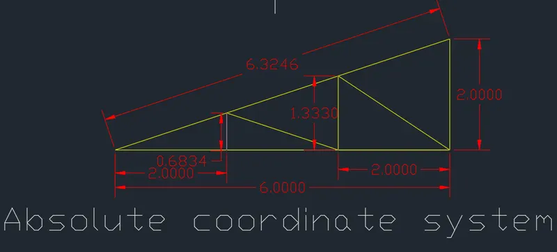
Procedure:
- Type L in command box and press enter.
- Specify the start point 1,1 in command box and press enter.
- Specify next point 3,1 in command box and press enter.
- Specify next point 3,1.667 in command box and press enter.
- Specify next point 5,2.333 in command box and press enter.
- Specify next point 7,1 in command box and press enter.
- Specify next point 7,3 in command box and press enter.
- Specify next point 5,2.333in command box and press enter.
- Then specify or type next point 3,1.667 in command .
- Specify next point 1,1 in command box or close enter.
- Specify next point 3,1 in command box and press enter.
- Specify next point 5,1 in command box and press enter.
- Specify the next point 7,1 in command box and press enter twice.
Result:
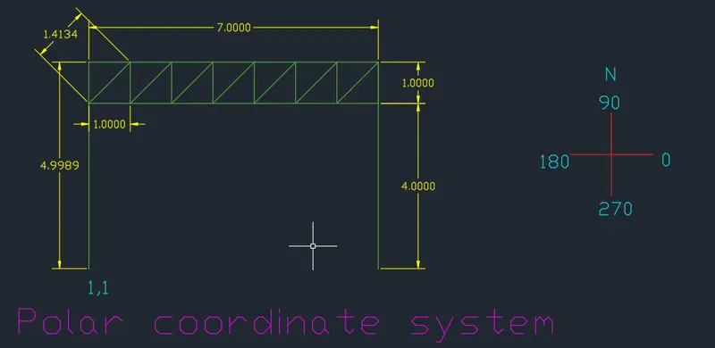
[4.] AIM:Drawing the Truss using relative Polar coordinate system method
Procedure :
- Choose the line command.
- Specify the start point 1,1 in the command box and press enter.
- Type the next point as @4<90 in command box and press enter.
- Type the next point as @1.414<45 in command box and press enter.
- Type the next point as @1<270 in command box and press enter.
- Type the next point as @1.414<45 in command box and press enter.
- Type the next point as @1<270 in command box and press enter.
- Type the next point as @1.414<45 in command box and press enter.
- Type the next point as @1<270 in command box and press enter.
- Type the next point as @1.414<45 in command box and press enter.
- Type the next point as @1<270 in command box and press enter.
- Type the next point as @1.414<45 in command box and press enter.
- Type the next point as @1<270 in command box and press enter.
- Type the next point as @1.414<45 in command box and press enter.
- Type the next point as @1<270 in command box and press enter.
- Type the next point as @1.414<45 in command box and press enter.
- Type the next point as @1<270 in command box and press enter.
- Type the next point as @7<180 in command box and press enter.
- Type the next point as @1<90 in command box and press enter.
- Type the next point as @7<0 in command box and press enter.
- Type the next point as @5<270 in command box and and press enter twice.
Result:
Result:
- Geometries P-1 and P-2 are drawn successfully using all the coordinates system methods.
- Geometries from P-4 to P-10 are drawn successfully by using one of the coordinate system method as mentioned above.
- Profile of wood, Queen Post Truss and mono pitch is drawn successfully by using method as mentioned above.
- By following the procedure as mentioned above the outputs are obtained as shown above.