Creating Levels, Grids, Layout and model elements for a residential unit using REVIT
{1}.What is BIM? Summarize the features of BIM and the benefits of using BIM over 2D CAD tools.
Building Information Modelling
- Building information modeling is a process supported by various tools, technologies and contracts involving the generation and management of digital representations of physical and functional characteristics of places.
- Building information models are computer files which can be extracted, exchanged or networked to support decisionmaking regarding a built asset.
- BIM software is used by individuals, businesses and government agencies who plan, design, construct, operate and maintain buildings and diverse physical infrastructures, such as water, refuse, electricity, gas, communication utilities, roads, railways, bridges, ports and tunnels.
Levels in BIM
- Level 0 BIM: Paper-based drawings + zero collaboration
- Level 1 BIM: 2D construction drawings + some 3D modeling
- Level 2 BIM: Teams work in their own 3D models
- Level 3 BIM: Teams work with a shared 3D model
- Levels 4, 5, and 6 BIM: Adding in scheduling, cost, & sustainability information
Advantages of BIM :-
- BIM offers more complete representation of a building’s design.
- With CAD, we typically draw floor plans and then sections. But with BIM, we create the elements in one view, and they appear in all views in which their visibility is turned on.
- It takes more than the building’s core components into account.
- For example, BIM allows to design electrical and HVAC systems, as well as the building itself.So that the project team can take full advantage of the space and resources available.
- BIM Collect the documents into a single database.
- This allows for instant updates, so we won’t waste time searching for documents when we need to make changes.
- A BIM model will allow you to prefabricate important components ahead of time.
- We won’t have to adjust them based on the building design.
- Resource tracking is a key component of BIM models.
- The models we give to our clients update constantly as you work on your project.
- Client can check in any time, which leads to quicker approval and more efficient project development.
- We will be able to figure out how much of each resource we need during the design stage.
- This improves the flow and efficiency of construction.
FEATURES OF BIM
- BIM allows to bring all your designs, including CAD models, into a single database.
- Using the cloud, BIM provides access to this database to all project members. we’ll all work on the same models, which allows for quick changes as needed.
- When used correctly, It helps the entire team visualise the project. In fact, this is one of the main benefits of BIM in construction.
- The team can spot project issues before construction even starts.
- The methodology allows us to design every aspect of a building. In addition to the building itself BIM models feature electrical wiring and other important aspects of design. This creates a more realistic digital representation of the final product.
{2}. Understand the concept of Categories, Families, Elements, Instances in Revit. Go to Insert Tab, choose a category. Pick a family and element. Understand the instances and insert them into the Revit model.
Category:
- A Category controls the organization, visibility, graphical representations, and scheduling options of Families within the Project.
- Simply Category are the materials which are to be required fora house and are visible through eyes. Ex:Doors,windows,stairs etc.
Family:
- A Family is a grouping of 2D and/or 3D information that serves to represent a discrete building or documentation element in the Project.
- It defines parametric, graphical, and documentation requirements.
- Simply these are the sub category of the topic mentioned above.i.e. If we take table category,we need to specify the shape of it ,so the familiesare defines about which type of shape u want in that category.
Elements:
- Element shows about the size and dimension of the families .
- It differentiate from the other families and can be used accordigly as the space required.
Type:
- A Type is a specific representation in a Family defined by distinct parametric, graphical, and documentation characteristics which makes it unique from other Types in the Family .
- Simply it shows about the size and dimension of the families .
- It differentiate from the other families and can be used accordigly as the space required.
Instance:
- Instance is an individual representation of a Type in the Project defined by unique parametric, graphical, and documentation characteristics which makes it unique from other Instances in the Project .
- It is a parameter as if the familiy is made INSTANCE ,the changes in dimension done on it doesn't affect the dimesnsion of the same family.
Aim: To create a family in Revit
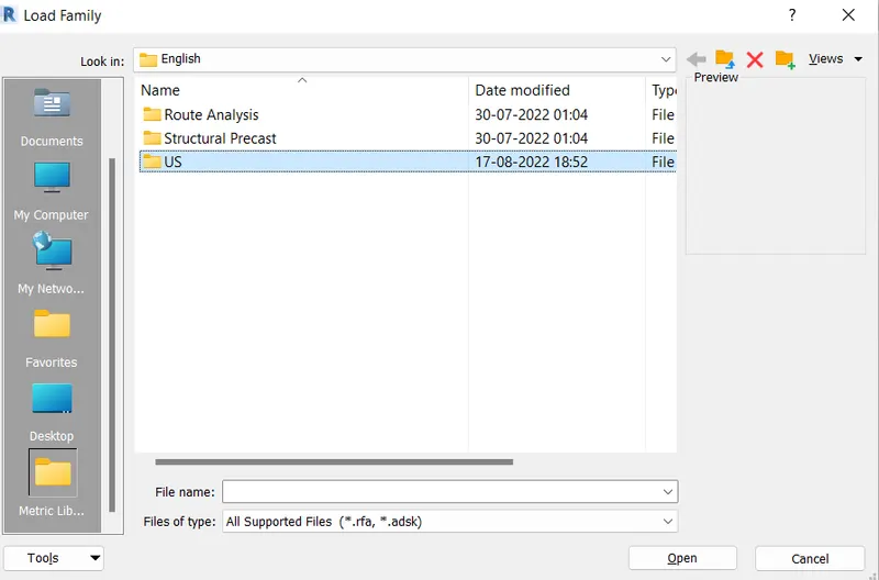
Step 1: Click on insert tab ----->go to "load family"

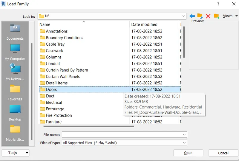
Step 2: Add Family
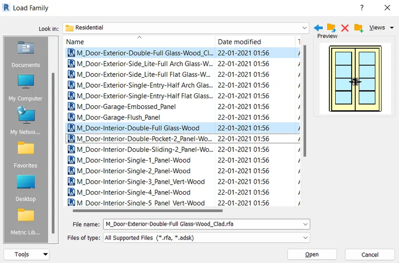
- Click on the US folder ---->Select DOOR ----->Select Different type of Door that suitable for our project
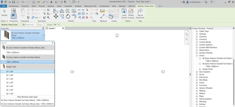
Step 3: Show the Family in Project browser
- Families can also be added ------> project browser and Properties Browser as follows
3) Setting up a Project – Open a project file with an architectural template. Save the file with an appropriate name. Set up the project units to Imperial / Metric based on your convenience of modeling. Complete the project information under the Manage tab. Set up the maximum backups for project file to 3
AIM: To Set up a project
Procedure:
Step 1:
- Open REVIT
- Creating Architectural Template and Saving Template
- Click on New ------->Architectural template
- Click on create new “project”.
- Click OK to open the Architectural template
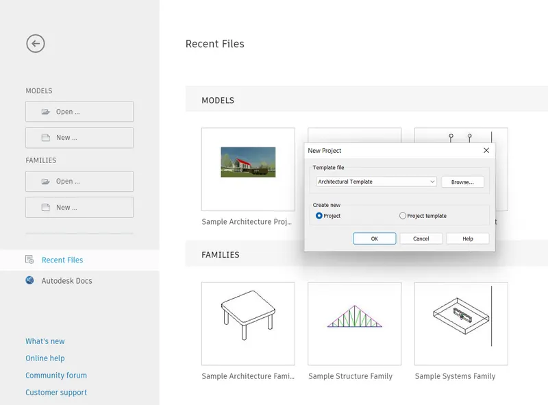
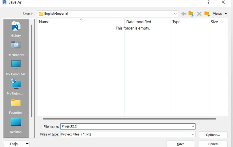
Step 2: Project settings Save the project with the name PROJECT
- Save the project as 2.1
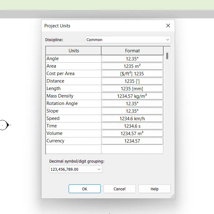
Step 4:Set up the project units to Metric.
- Set up the project units to Metric by typing UN command.
- Then changes all the Unit to Matric if it is in the Imperial system.
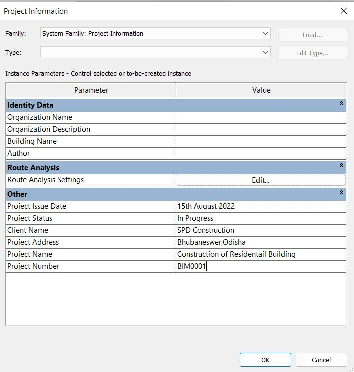
Step 3: Project settingsProject Information in the MANAGE TAB
- Go to manage tab.
- Select the option project information.
- Completely fill the information in detail
Step 4:Creating backups of the file
- Go to the file menu.
- Select save as option -----> project.
- A save as dialog box will be appearing on the screen.
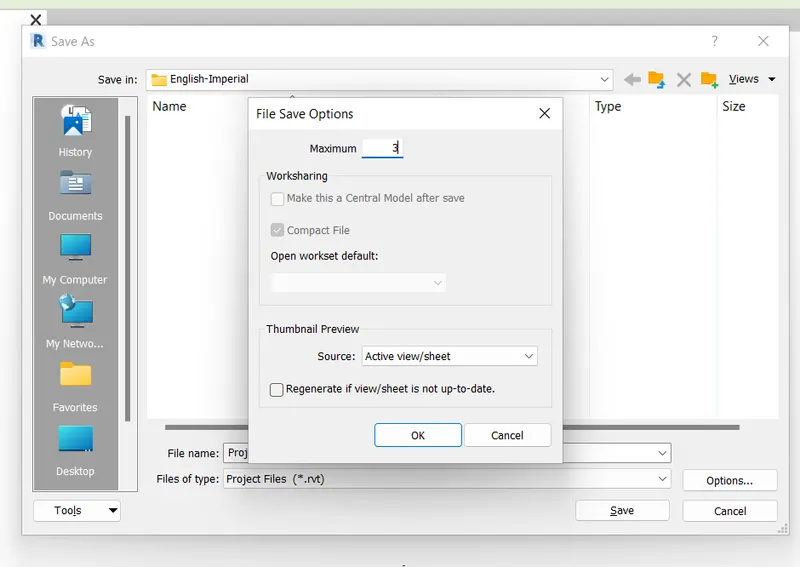
- Click on the OPTIONS TAB in left bottom of the dialog box -----> set the maximum backups as 3.
- The end is shown in the result
4) Understand the concept of Levels and Grids. Follow the naming and conventions. Create the following Levels: (Convert to metric equivalents if the metric is your units)
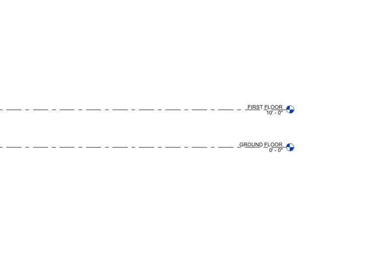
Ground Floor @ 0’
First Floor @ 10’
Second Floor @ 20’
Roof @ 30’
Grids Transverse Grids A, B,C, D, E @ 10’ spacing
Longitudinal Grids from 1 to 10 @ 20’ spacing
{A} AIM: To create levels and grids for standard layout
Procedure:
Step 1: Open REVIT
- Open Revit 2022.
- Open Architectural template and select project.
- A Revit screen will be opening.
Step 2:
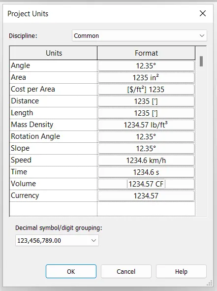
- Change the units from MM ----->Feet and Inches.
- Command UN
- Change the units to ----> Feet’s.
Step 3: creation of the different levels
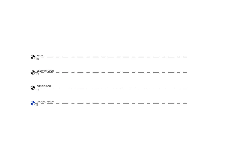
- Go to the view tab ------> Elevation.
- From the project browser section---------> Elevation------> East.
- Two basic levels will be displayed on the screen.
- Keep the bottom most level and delete the top level.
- Rename the bottom level as Ground Floor and rename the height as 0’
- Now go to the modify tab.
- Select copy command.
- Copy the levels to 10’, 20’, 30’.
- Rename the levels as ground floor, first floor, second floor and roof.
Step 4:Creating different grids line
- Go to Construction Tab -------> "Grid"
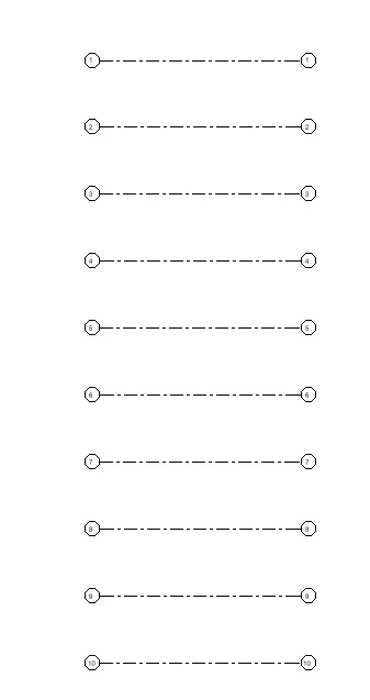
- Draw the Longitudinal Grids is already named as -----> 1.
- Copy the grid from the modify command and copy the grids at the interval of 20’ spacing 1---->10
- Draw the grid in the Transverse/vertical manner which is already named as -----> 11.
- Copy the grid from the modify command and copy the grids at the interval of 10’ spacing named as 11---->15.
- Draw the grids intersecting the Longitudinal grid and Rename 1,2,3,4,5 as A, B, C, D, E.
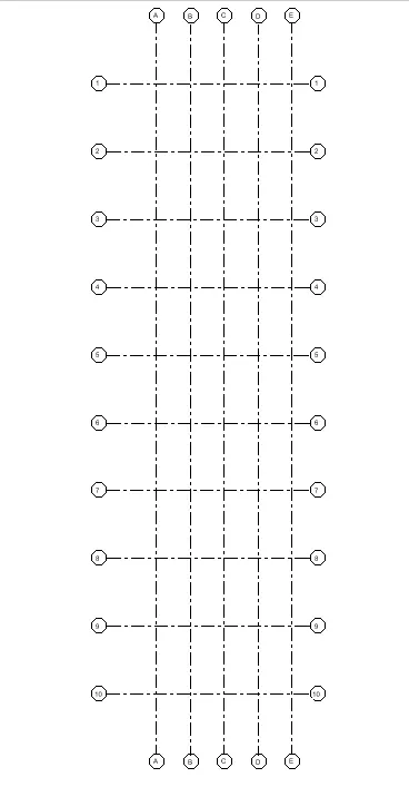
Result:
- The Levels and grids are created as required.
- Grids Transverse Grids A, B,C, D, E @ 10’ spacing
- Longitudinal Grids from 1 to 10 @ 20’ spacing
5) 3D modeling of the residential unit – From looking at your house / or a place you aspire. Create a conceptual layout of the residential unit. You can measure using tape or you can access your residential plan to create a similar layout.
A). AIM: To create 3D modeling of the residential unit
Procedure:
Step 1:
- Open Revit 2022 with architectural template.
- Enter UN command and set the dimensions to feet and inches.
Step 2:
- Set the level for the drawing.
- Creat 3 level.
- Ground Floor as Level.1
- First floor as Level.2
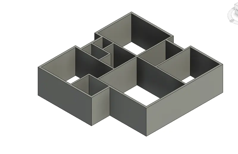
- Go to the wall option in the architectural tab.
- Set the hight as 10'.
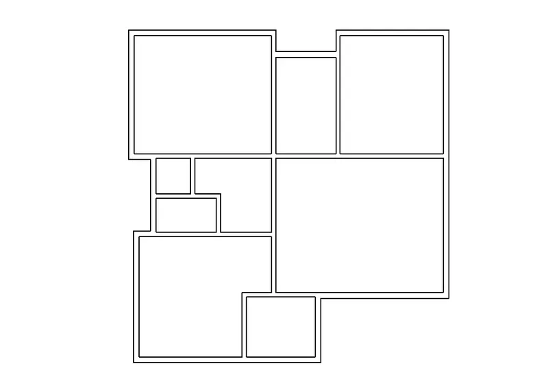
- Draw the external walls having thickness 8".
- Again, go to wall option and draw the internal walls by changing the wall thickness as 6".
- Plan Ready------->
- click on default 3D view from quick access toolbar
- from the View Cube ->click on SE corner to get into the view
- Clcik on visual style ->realistic view
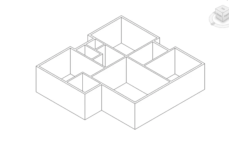
RESULT: We created a conceptual layout of the residential unit .
6) In the layout created draft the level of details you are planning to include – Dimensions of room, components you plan to add in the residential unit.
PROCEDURE:
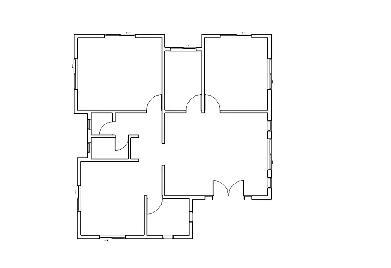
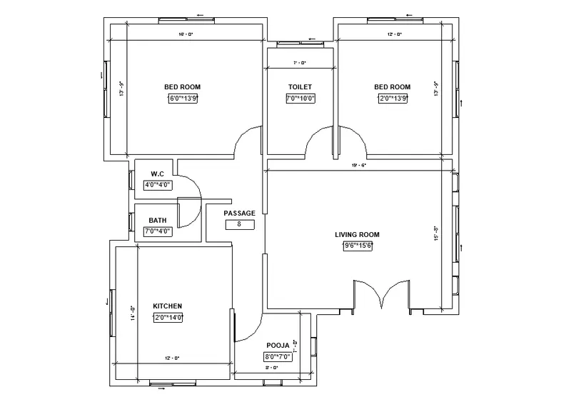
For Dimensions
STEP.1:
- OPen the file
- Go to Annotate TAb
- Click on "ALIGNED"
- Click on the inner walls for the inner dimensions of rooms
- Do it for every room of the plan to give dimension of the room
- For the Plan Size ,click on exterior side of the walls on both the farthest wallsof plan
- Do it for both vertical and horizontal direction
STEP.2:
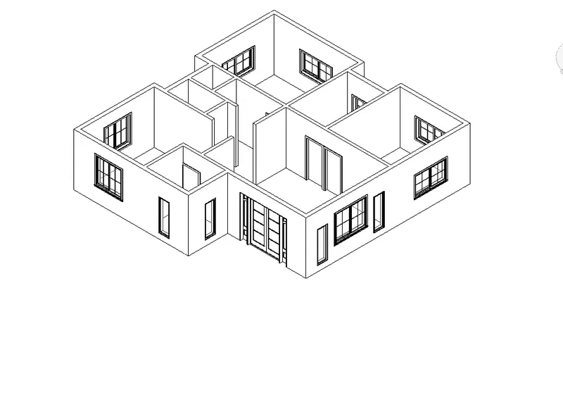
iNSERT dOOR AND WINDOW
- Go to floor plan
- Click on Insert Tab---->LOAD FAMILY
- A new window will open
- Select the family----->Click OK
- Go to the family folder uyou want to insert in the plan Ex:Doors,windows
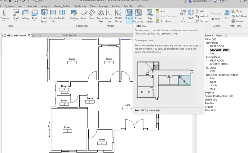
STEP.3:or Tagging room
- Go to Architectural tab
- Click on "ROOM" on the modify tab.
- move the cursor inside the room you want to give tag
- Click in the tag name to rename it.
STEP.4:
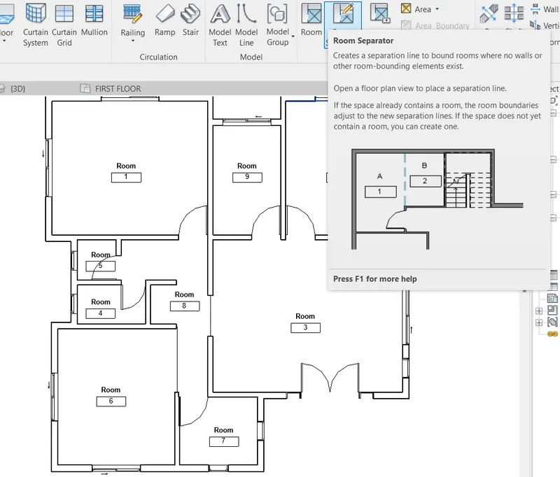
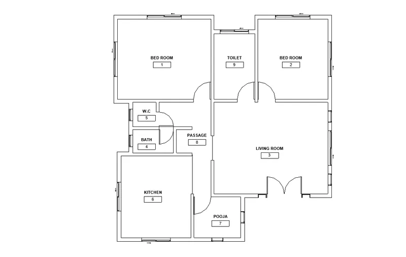
- If there is problem in tag the room then use Room separation for separate the room.
- Then use the room tag for tagging the remaining room.
STEP.5: Dimension Detail
Edit the room tag box to write the Dimension detail of the plan.
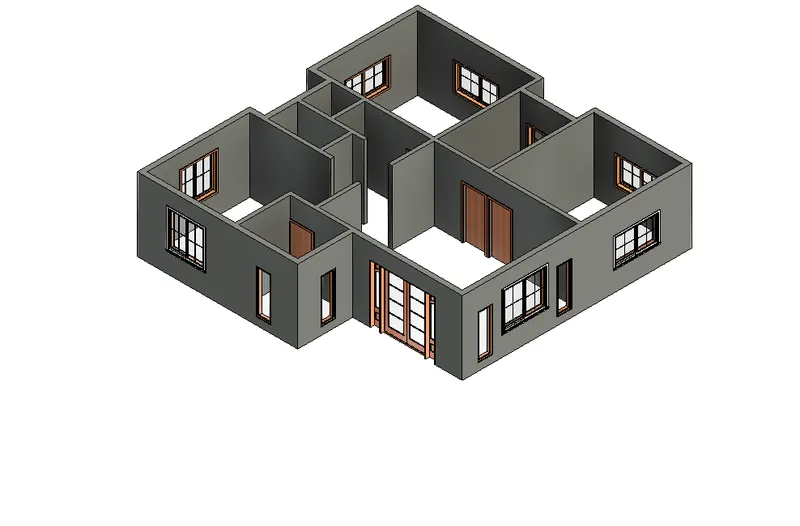
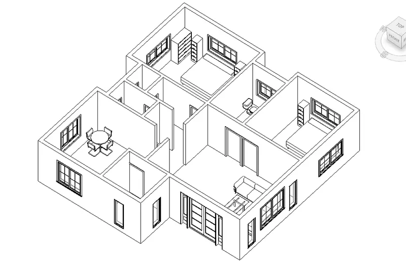
7. Identify the residential model elements such as Door, Windows, Tables, Chair, Couch, Bed, Lamps from the library and insert them to the model .
Continue from the previous question that we are craeted the Internal and External Wall
- Go to floor plan
- Click on Insert Tab---->LOAD FAMILY
- Creat Main Door
- A new main door will open
- Go to the family folder to insert in the plan Ex:Door, Windows.
- Select the family----->Click OK
In 3d Realistic view:-
- Similarly select the Tables, Chair, Couch, Bed, Lamps family To bring it on the project browser panel
- Go to project browser panel
- Go to family and expand it---->Go to certain family as show below
- Select the element like ->click the element and move cursor to plan and release the button
- Insert all the elemnt in the plan in appropriate place.
Realistic view :-
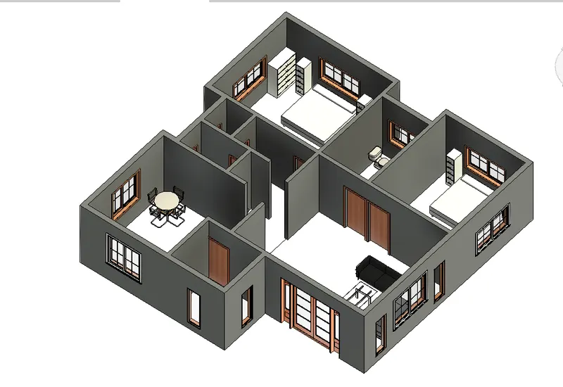
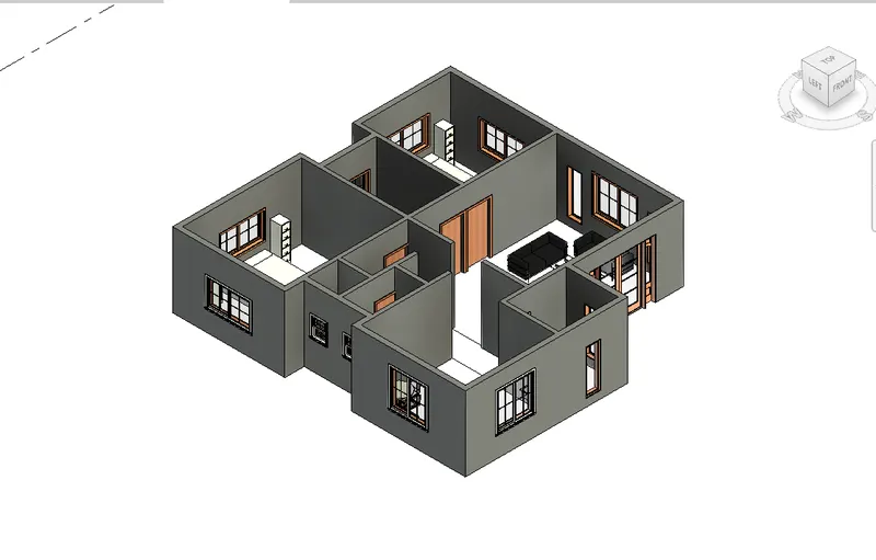
RESULT:
Hear I Design the residential model elements such as Door, Windows, Tables, Chair, Couch, Bed, Lamps from the library and insert them to the model in proper manner.