Creating various 3D Models like Furniture, Footing, Girder, Column drop with panel and Gable Wall in AutoCad
1. Aim: To draw the 3D wireframe model as shown in the figure.
Introduction:
- The 3Dwireframe model given is a furniture equipment in the house.
- The 3d wireframe model is drawn in different coordinate systems such as rectangular coordinate system, spherical coordinate system, relative coordinate system and cylindrical coordinate system.
Procedure:
- Open AutoCAD
- In Startup settings start from scratch select Imperial (Feet and Inches)
- Open grid and snap settingsClick on AutoCAD application and open this application
- In default setting click on use a wizard and in that advance setting and set unit as Architectural and precision as 0’0” and press Next
- Set Angle as Decimal Degree and precision as 0 and click next
- Set Angle Measure as EAST and press NEXT
- Set Angle Direction as Counter-Clockwise and press NEXT
- Set Area by providing Length as 50’ and Width as 50’
- Press finish
- Keep ortho, Object snap >ON
- Keep Snap and Grid > Off
- Un+enter
- Type > Architectural, Precision > 0’0”
- Units to scale inserted content > Inches
- Change the workspace setting of AutoCAD from ‘drafting and annotation’ to ‘3D Modeling’
Step 1:
- Creating Layers
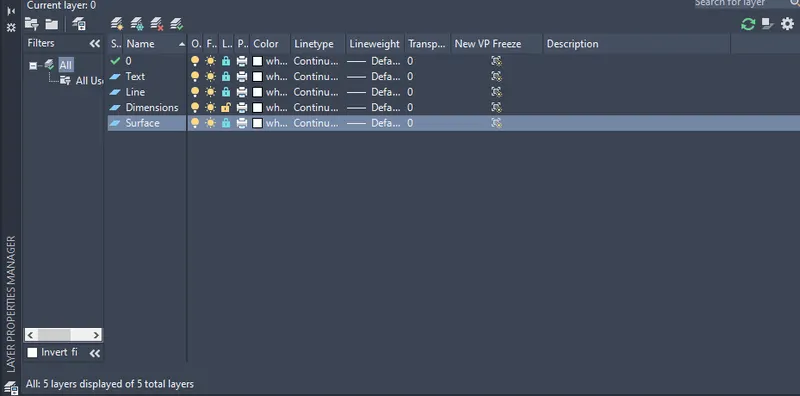
- Open Layer properties and create new layers by clicking on new layer or right click on any layer and select new layer to create new layer
- Layers are created as follows
Step 2:
- Select workspace switching > 3D Modelling
- Select Visual style control > 2D Wireframe
- Take 3D Orbit command
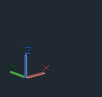
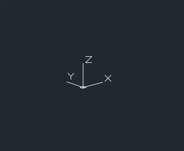
- Select view such as the UCS direction is as shown below
Step 3:
- Creating Top box view
- Take line command
- Select first point > Anywhere in the drawing
- Line specify next point > @0,0,2’6” > Enter (Relative coordinate system)
- Line specify next point > @0,3’,0> Enter(Relative coordinate system)
- Line specify next point > @0,0,-2’6” > Enter (Relative coordinate system)
- Line specify next point > @0,-2”,0 > Enter (Relative coordinate system)
- Line specify next point > @0,0,2’4” > Enter (Relative coordinate system)
- Line specify next point > @0,-2’8”,0 > Enter (Relative coordinate system)
- Line specify next point > @0,0,-2’4” > Enter (Relative coordinate system)
- Line specify next point > @0,-2”,0 > Enter (Relative coordinate system)
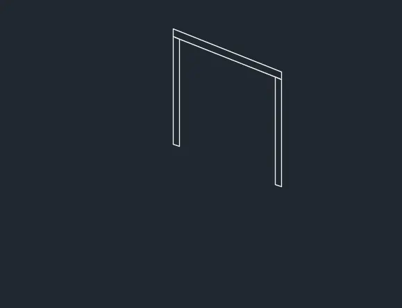
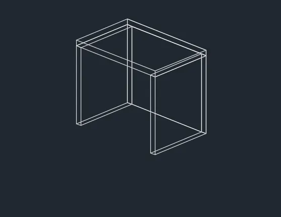
- It will shows the following result
Step 4:
- Take a rectangle command
- pecify first corner point > Click on top left corner point
- Click > Dimension
- Specify Length > 2’2”
- Specify width > 3’
- Enter
- Use line command to connect the rectangle as shown below
Step 5:
- Take 3D face command
- Specify all the four point of the top rectangle
- Enter > Hide > Enter
- Similarly do the 3D face command to all the faces of the drawing
- Click on ANNOTATION tab
- Click on Dimension
- Click > Manage dimension style
- New
- Style name > 3D
- Set the characteristics of dimensions as
- Select the yellow colour for the dimension style and extension line
- Select arrowhead size as 4”
- Select the text as green colour
- Then select linear dimensions
- Provide the linear dimension
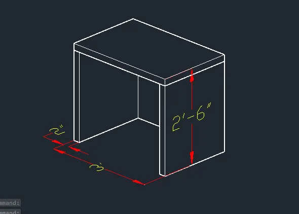
- It will shows the following result
Result:
- The 3d model of the furniture equipment is drawn in the above steps.
- The result consists of model assigned with layer.
- The model is drawn using all the coordinate systems.
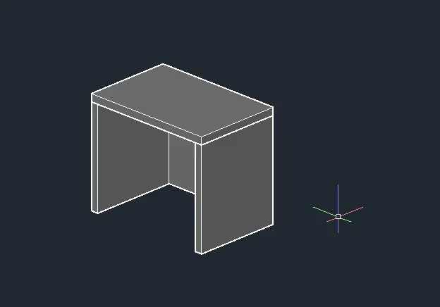
- 3DFACE command is used to draw surface to all the faces. Result is shown three different
- view style controls such as 2Dwireframe, Hidden, and shaded.
- All dimensions are in feet and inches
- 1. 2Dwireframe model
- 2. Hidden model
- 3. Shaded Model
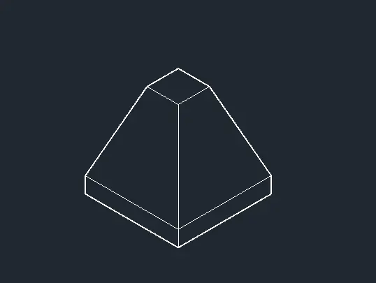
2. Aim: To draw the 3D wireframe model of an isolated footing as shown in the figure
Introduction:
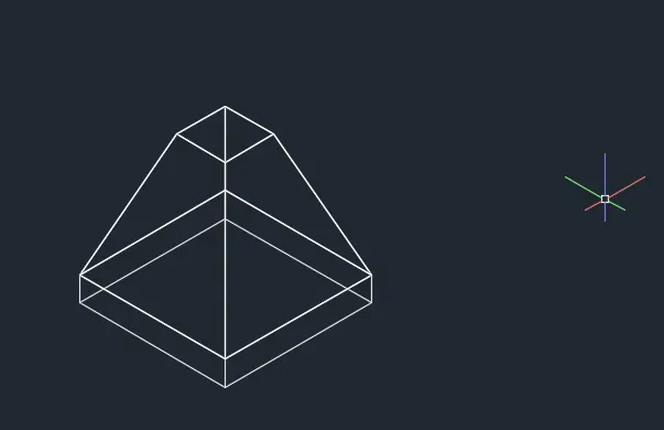
- The 3Dmodel given is an isolated footing. Isolated footing. An isolated footing is used to support a single column. Isolated footings are independent footings which are provided for each column.
- Because of its simplicity and economical nature, it is most commonly used reinforcement footing. This 3D model is of trapezoidal tapered isolated footing.
Procedure:
- Open AutoCAD
- In Startup settings start from scratch select Imperial (Feet and Inches)
- In default setting click on use a wizard and in that advance setting and set unit as Architectural and
- precision as 0’0” and press Next
- Set Angle as Decimal Degree and precision as 0 and click next
- Set Angle Measure as EAST and press NEXT
- Set Angle Direction as Counter-Clockwise and press NEXT
- Set Area by providing Length as 5’ and Width as 5’
- Press finish
- Keep ortho, Object snap >ON
- Keep Snap and Grid > Off
- Un+enter
- Type > Architectural, Precision > 0’0”
- Units to scale inserted content > Inches
- Enter
- Select workspace switching > 3D Modelling
- Select Visual style control > 2D Wireframe
Step 1: Creating Layers
- Open Layer properties and create new layers by clicking on new layer or right click on any layer and select new layer to create new layer
- Layers are created as follows
Step 2:
- Take 3D Orbit command
- Select view such as the UCS direction is as shown below
Step 3: Creating bottom surface
- Take rectangle command
- Specify corner point anyehere in the drawing
- Click > Dimension
- Specify Length > 3’
- Specify Width > 3’
- Enter
- Take rectangle command
- Specify corner point anyehere in the drawing
- Click > Dimension
- Specify Length > 1’
- Specify Width > 1’
- Enter
- By keeping object snap on
- Keep the small rectangle such as, both rectangle shows the same centre point
- Take move command
- Select object > Click on small rectangle
- Move it in a Z axis at a distance of 2’6”
- Take the line command
- Join all the corners of the both rectangle as shows below
Step 4:
- Take 3D face command
- Specify all the four point of the top rectangle
- Enter > Hide > Enter
- Similarly do the 3D face command to all the faces of the drawing
- Take the extrude command
- Select object > Click on the bottom rectangle
- Specify extrude height > 6”
- Enter
- Change the visual style control > Hidden
Step 5:
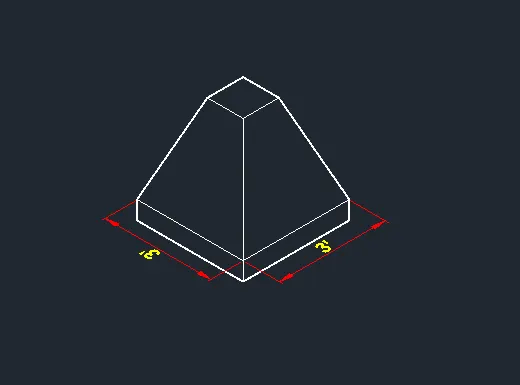
- Click on ANNOTATION tab
- Click on Dimension
- Click > Manage dimension style
- New
- Style name > 3D
- Set the characteristics of dimensions as
- Select the yellow colour for the dimension style and extension line
- Select arrowhead size as 4”
- Select the text as cyan colour
- Then select linear dimensions
- Provide the linear dimension
- It will shows the following result
Result:
- The 3d model of the Isolated tapered footing is drawn in the above steps.
- The result consists of model assigned with layers.
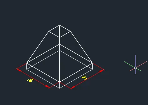
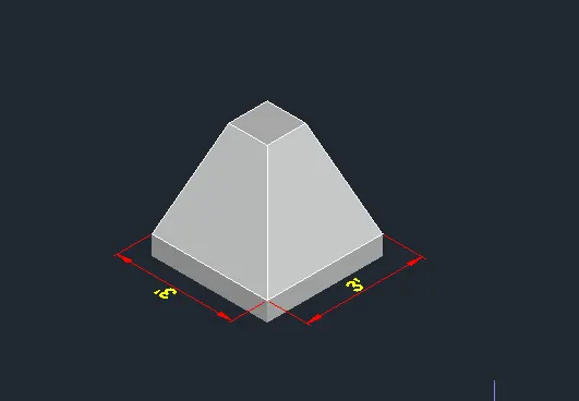
- The model is drawn using extrude command. Region command is used to draw surface to all the faces. Result is shown three different view style controls such as 2Dwireframe, Hidden, and shaded.
- All dimensions are in feet and inches
- 1. 2Dwireframe model
- 2.Hidden model
- 3. Shaded Model
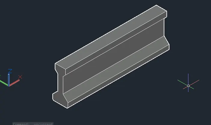
3. Aim: To draw the 3D wireframe model of an AASTHO Type Girder as shown in the figure
Introduction:
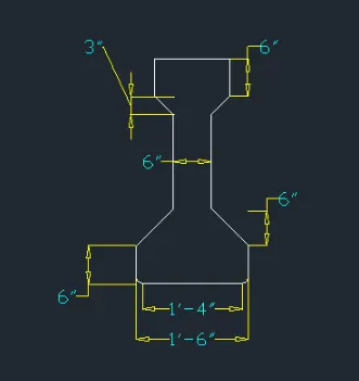
- The 3Dmodel given is an AASHTO Type Girder I section. AASHTO girders are classified into 5 different types depending on their dimensions of flange and web.
- Following figure shows the types of AASHTO-I beams at different dimensions. As per the dimensions of the given figure the AASHTO girder type is II.
Procedure:
- Open AutoCAD
- In Startup settings start from scratch select Imperial (Feet and Inches)
- Click on AutoCAD application and open this application
- Type QNEW in command bar and enter
- Select default setting as Imperial
- In default setting click on use a wizard and in that advance setting and set unit as Architectural and
- precision as 0’0” and press Next
- Set Angle as Decimal Degree and precision as 0 and click next
- Set Angle Measure as EAST and press NEXT
- Set Angle Direction as Counter-Clockwise and press NEXT
- Set Area by providing Length as 50’ and Width as 50’
- Press finish
- Keep ortho, Object snap >ON
- Keep Snap and Grid > Off
- Un+enter
- Type > Architectural, Precision > 0’0”
- Units to scale inserted content > Inches
- Enter
- Select workspace switching > 3D Modelling
- Select Visual style control > 2D Wireframe
- Select view control > Top
Step 1: Creating Layers
- Open Layer properties and create new layers by clicking on new layer or right click on any layer and select new layer to create new layer
- Layers are created as follows
Step 2:
- Take 3D Orbit command
- Select view such as the UCS direction is as shown below
Step 3: Creating AASTHO type girder
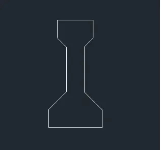
- Take line command
- Select first point > Anywhere in the drawing
- Line specify next point > 1’6” > Enter keeping curser right side
- Line specify next point > 6” > Enter keeping curser Up side
- Enter
- Take the offset command
- Specify distance as 6”
- Select object > Click on the horizontal line
- Similarly by using the line and offset command complete the plan as shown below
Step 3: Creating 3D beam section
- Take the fillet command
- Select fillet radius > 1”
- Select multiple
- Select the object which have to give the fillet command as per shown below
- Click on ANNOTATION tab
- Click on Dimension
- Click > Manage dimension style
- New
- Style name > 3D
- Set the characteristics of dimensions as
- Select the yellow colour for the dimension style and extension line
- Select arrowhead size as 4”
- Select the text as cyan colour
- Then select linear dimensions
- Provide the linear dimension
- It will shows the following result
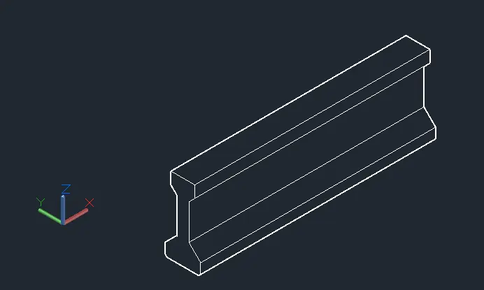
Result:
1. 2Dwireframe model
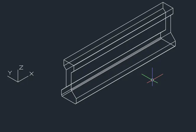
2. Hidden model
3. Shaded Model
4. Aim: To draw the 3D wireframe model of an Drop column as shown in the figure
Introduction:
- The 3Dmodel given is a drop column used for construction of flat slabs.
- A drop column is used when beam is not required in the design. Drop is a part of the slab around the column, which have greater thickness than the rest of the slab. The drop column not only eliminates the need of beam but also gives a plain ceiling and great appetence, better light diffusion, more open rooms.
- Flat slab is design by two methods
- 1. Direct Design Method.
- 2. Equivalent Frame Method
Procedure:
- Click on AutoCAD application and open this application
- Type QNEW in command bar and enter
- Select default setting as Imperial
- In default setting click on use a wizard and in that advance setting and set unit as Architectural and
- precision as 0’0” and press
- Next
- Set Angle as Decimal Degree and precision as 0 and click next
- Set Angle Measure as EAST and press NEXT
- Set Angle Direction as Counter-Clockwise and press NEXT
- Keep ortho, Object snap >ON
- Keep Snap and Grid > Off
- Un+enter
- Type > Architectural, Precision > 0’0”
- Units to scale inserted content > Inches
- Enter
- Select workspace switching > 3D Modelling
- Select Visual style control > 2D Wireframe
- Select view control > Top
Step 1: Creating Layers
- Open Layer properties and create new layers by clicking on new layer or right click on any layer and select new layer to create new layer
- Layers are created as follows
Step 2:
- Take 3D Orbit command
- Select view such as the UCS direction is as shown below
Step 2: Creating column top view
- Select view control > Top
- Take rectangle command
- Select first corner point > Anywhere in the drawing
- Click > Dimension
- Specify Length > 4’6”
- Specify width > 4’6”
- Enter
- Take a circle command
- Specify centre > anywhere
- Click > diameter
- Specify diameter > 3’6”
- Enter
- Take a circle command
- Specify centre > Same centre
- Click > diameter
- Specify diameter > 1’6”
- Enter
- Take move command
- Select object > Click the smaller circle
- Specify distance > 1’
- And move it along Z axis
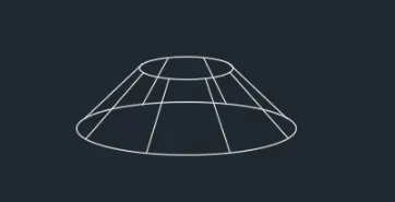
- Take the extrude command and extrude the smaller circle as per shown below
Step 3:
- Take a circle command
- Specify centre > anywhere
- Click > diameter
- Specify diameter > 1’6”
- Enter
- Make it region
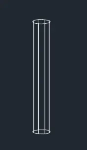
- Take extrude command
- Select object > Click on the latest circle drawn
- Specify Extrude height > 10’
- Enter
Step 4:
- Take region command
- Select object > Click on the rectangle
- Take extrude command
- Extrude object > Click the rectangle
- Extrude height > 6”
- Enter
- Take move command
- Move the above two diagram at the centre of rectangle by keeping object snap on
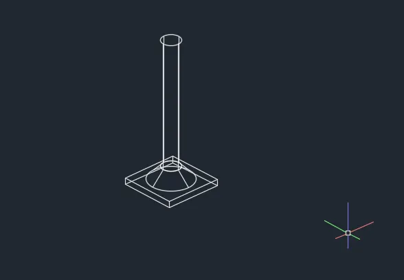
- It will shows following result
Result:
- The 3d model of a drop column is drawn in the above steps. The result consists of model assigned with layers.
- The model is drawn using extrude command. Region command is used to draw surface to all the faces.
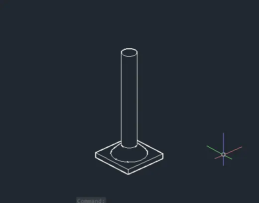
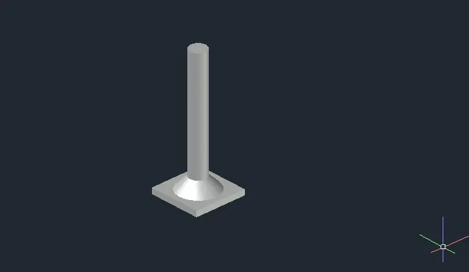
- Result is shown First the drop column plan view is drawn in 2D and then region is created and extruded.
- All dimensions are in feet and inches
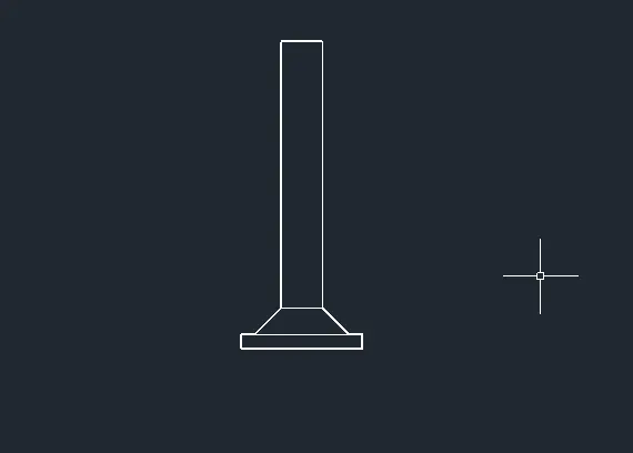
1. 2Dwireframe model
2. Hidden model Front view
3. Hidden model
4.Shaded Model
5. Aim: To draw the 3D wireframe model of a wall as shown in the figure.
Introduction:
- The 3Dmodel given is a wall with door opening.
- The 3d view of a wall is shown above with a door opening.
- The thickness of the wall is given 9” which is standard thickness of outer walls of a house.
- The dimension of the door opening is given as 3’X7’. The top of the wall is gable shape and is also known as gable wall.
Procedure:
- Open AutoCAD
- In Startup settings start from scratch select Imperial (Feet and Inches)
- In default setting click on use a wizard and in that advance setting and set unit as Architectural and
- precision as 0’0” and press
- Next
- Set Angle as Decimal Degree and precision as 0 and click next
- Set Angle Measure as EAST and press NEXT
- Set Angle Direction as Counter-Clockwise and press NEXT
- Set Area by providing Length as 50’ and Width as 50’
- Press finish
- Keep ortho, Object snap >ON
- Keep Snap and Grid > Off
- Un+enter
- Type > Architectural, Precision > 0’0”
- Units to scale inserted content > Inches
- Enter
- Select workspace switching > 3D Modelling
- Select Visual style control > 2D Wireframe
Step 1: Creating Layers
- Open Layer properties and create new layers by clicking on new layer or right click on any layer and select new layer to create new layer
- Layers are created as follows
Step 2:
- Take 3D Orbit command
- Select view such as the UCS direction is as shown below
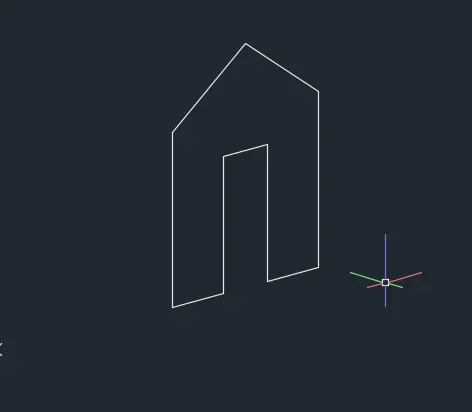
Step 3: Creating front view
- Take line command
- Select first point > Anywhere in the drawing
- Line specify next point > @3’6”,0,0 > Enter
- Line specify next point > @0,0,7’ > Enter
- Line specify next point > @3’,0,0 > Enter
- Line specify next point > @0,0,-7’ > Enter
- Line specify next point > @3’6”,0,0 > Enter
- Line specify next point > @0,0,9’ > Enter
- Line specify next point > @-10,0,0 > Enter
- Line specify next point > @0,0,-9’ > Enter
- From the bottom midpoint of the door
- Draw the line of 12’6”
- Join the corners of the top wall to top og the line drawn
- Erase the unwanted line
Step 3: Creating 3D view
- Take a Region command
- Select the object > Select whole diagram
- Enter
- Take extrude command
- Select the object > Select the object which is regioned
- Specify extrude height > 9”
- Enter by extruding it along Y-Axis
- It will shows the following results
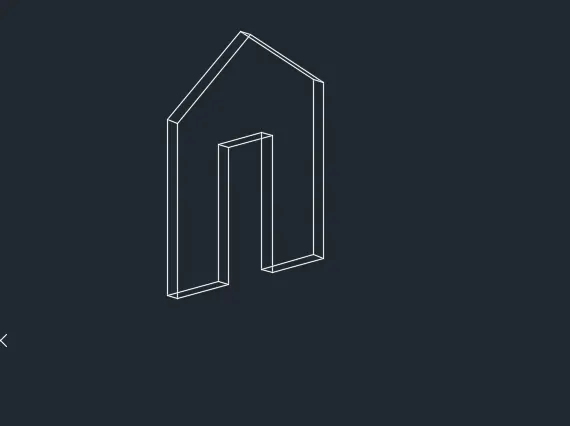
Result:
- The 3d model of a wall with a door opening is drawn in the above steps.
- The result consists of model assigned with layers.
- The model is drawn using extrude command.
- Region command is used to draw surface to all the faces.
- Result is shown three different view style controls such as 2Dwireframe, Hidden, and shaded.
- First the wall plan view is drawn with the door opening in 2D and then region is created and extruded with door opening.
1. 2Dwireframe model
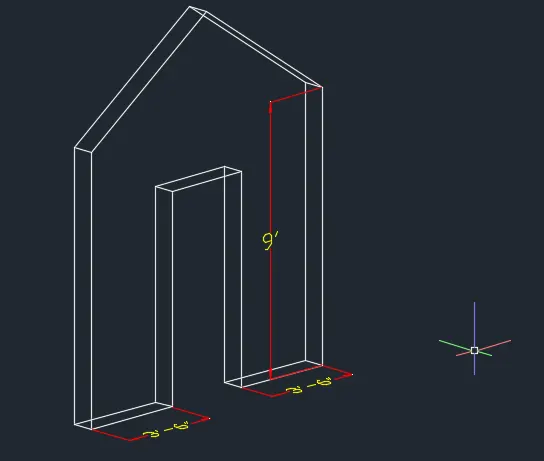
2. Hidden model
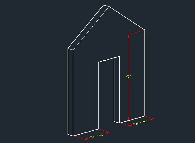
3. Shaded Model
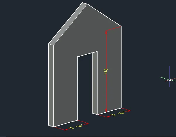
Final Result:1
Final Result:2
Final Result:3
Final Result:4
Final Result:5