Creating a Floor plan, Footing detail and Isometric view using AutoCad
AIM : To create Cross-Sectional View and Isometric View of some Engineering Drawing using AutoCAD.
Introduction:
(a)Cross-Section view :
- It is a typical or representative sample of a larger group.
- It is a surface or shape exposed by making a straight cut through something, especially at right angles to an axis.
- In geometry, a Cross Section is the non-empty intersection of a solid body in three-dimentional space with a plane, or the analog in higher-dimensional spaces.
- Cutting an object into slices creates many parallel cross-sections.
(b)Isometric View
- A 2D isometric View is a flat representation of a 3D isometric projection.
- This method of drawing provides a fast way to create an isometric view of a simple design.
- Distances measured along an isometric axis are correct to scale, but because we are drawing in 2D, we cannot expect to extract other 3D distances and areas, display objects from different viewpoints, or remove hidden lines automatically.
Commands used in this challenges
- Line
- Polyline
- Rectangle
- Trim
- Chamfer
- Offset
- Isometric Views
- Copy
Question 1: Drawing C1 figure in AutoCAD
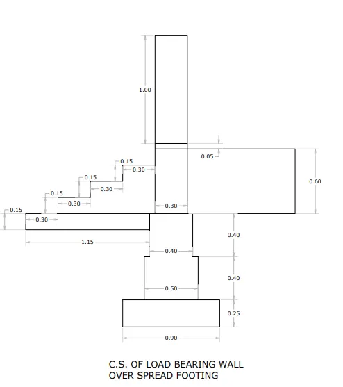
Aim: To draw the figure of a C.S. of load bearing wall over spread footing by using AutoCAD.
Introduction
- Wall footing is a type of footing which is used to support walls, both structural and non-structural.
- This footing takes load from walls of structure and transfer the loads to the soil below. The load is transferred such that the load bearing capacity of the soil does not get reduced.
- It also maintains sufficient safety against the overturning and sliding and also avoids excessive settlement.
Procedure
Step.1: Type ‘rec’ in command line or select rectangle from the draw tool bar
- Specify first corner point: let us assume first corner at (1,1) and press enter
- Specify other corner point: Type @0.9,0.25 and press enter
Step.2: Type ‘rec’ in command line or select rectangle from the draw tool bar
- Specify first corner point: Type (1.2,1.25) and press enter
- Specify other corner point: Type @0.5,0.4 and press enter
Step.3: Type ‘rec’ in command line or select rectangle from the draw tool bar
- Specify first corner point: Type (1.25,1.65) and press enter
- Specify other corner point: Type @0.4,0.4 and press enter
Step.4: Type ‘rec’ in command line or select rectangle from the draw tool bar
- Specify first corner point: Type (1.3,2.05) and press enter
- Specify other corner point: Type @0.3,0.6 and press enter
Step.5: Type ‘rec’ in command line or select rectangle from the draw tool bar
- Specify first corner point: Type (1.3,2.65) and press enter
- Specify other corner point: Type @0.3,0.05 and press enter
Step.6: Type ‘rec’ in command line or select rectangle from the draw tool bar
- Specify first corner point: Type (1.3,2.65) and press enter
- Specify other corner point: Type @0.3,1 and press enter
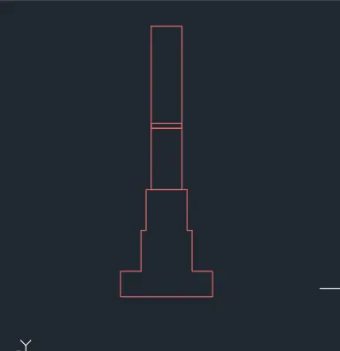
Step.7 :Type ‘trim’ in command line
- Remove the middle line.
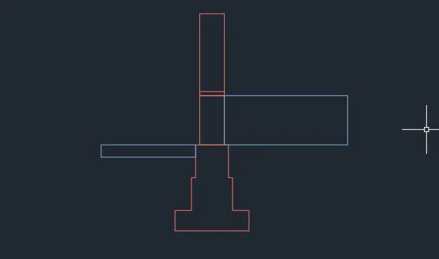
Step.7: Type ‘rec’ in command line or select rectangle from the draw tool bar
- Specify first corner point: Type (1.6,2.05) and press enter
- Specify other corner point: Type @1.5,0.6 and press enter
Step.8: Type ‘rec’ in command line or select rectangle from the draw tool bar
- Specify first corner point: Type (1.25,2.05) and press enter
- Specify other corner point: Type @-1.15, -0.15 and press enter
Step.9: Type ‘pl’ in command box or select polyline from the draw tool bar
- Specify start point: On snap or click F3 and click on the top edge of the rectangle and type @0.3,0 and press enter
- Specify next point: Type @0,0.15 and press enter
- Specify next point: Type @0.3,0 and press enter
- Specify next point: Type @0,0.15 and press enter
- Specify next point: Type @0.3,0 and press enter
- Specify next point: Type @0,0.15 and press enter
- Specify next point: Type @0.3,0 and press enter
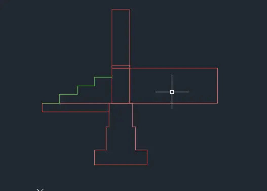
Result:
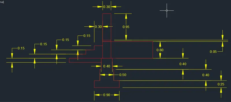
- All dimensions are in meter.
- Footing Drawing – Red Colour
- Dimensions – Yellow Colour
Question 2: Drawing of C.S. of Isolated Footing figure by using AutoCAD
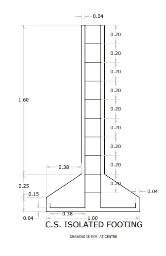
Aim: To draw the figure of C.S. of Isolated Footing
Introduction:
- Isolated footing is a type of footing which is placed at shallow depths and supports one column of the building.
- It is an independent footing designed to support an independent column.
- The shape of column can be rectangular, square or circle. Based on the crosssectional shape they are classified as Pad footing, Stepped footing and Sloped footing.
Procedure:
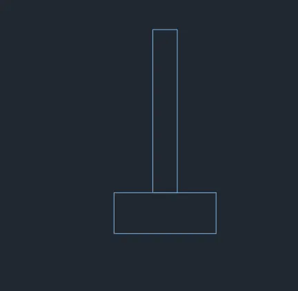
Type ‘rec’ in command line or select rectangle from the draw tool bar
- Specify first corner point: let us assume first corner at (1,1) and press enter
- Specify other corner point: Type @1,0.4 and press enter
Type ‘rec’ in command line or select rectangle from the draw tool bar
- Specify first corner point: Type (1.38,1.4) and press enter
- Specify other corner point: Type @0.24,1.60 and press enter
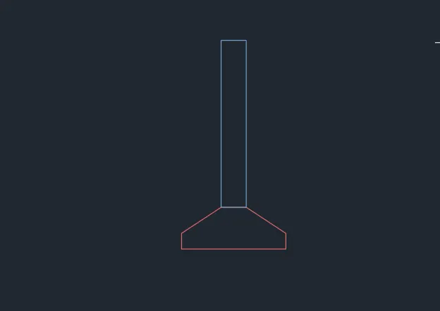
Type Chamfer in command box or select chamfer from the modify tool bar
Left side chamfering
- Type Chamfer And from options select distance
- Specify first chamfer distance for X axis: Type 0.38 and press enter
- Specify Second chamfer distance for Y axis: Type 0.25 and press enter
- Select first line: select top left horizontal part of the bottom rectangle
- Select second line: select top left vertical part of the bottom rectangle
- Press Enter
Right side chamfering
- Type Chamfer And from options select distance
- Specify first chamfer distance for X axis: Type 0.38 and press enter
- Specify Second chamfer distance for Y axis: Type 0.25 and press enter
- Select first line: select top right horizontal part of the bottom rectangle
- Select second line: select top right vertical part of the bottom rectangle
Type ‘pl’ in command box or select polyline from the draw tool bar
- Specify start point: Type 1.04,1.09 and press enter
- Specify next point: Type @0, -0.05 and press enter
- Specify next point: Type @0.38,0 and press enter
- Specify next point: Type @0,1.96 and press enter
- Specify next point: Type @0.16,0 and press enter
- Specify next point: Type @0,1.96 and press enter
- Specify next point: Type @0.38,0 and press enter
- Specify next point: Type @0,0.05 and press enter
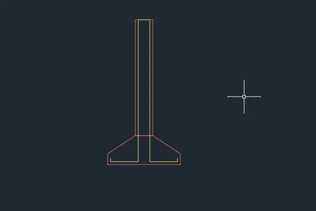
Type L or line and press enter
- Specify start point: Type 1.42,3 and press enter
- Specify next point: Type @0.16,0 and press enter
Type ‘o’ and press enter or click offset from the modify tool bar
- Specify offset distance: Type 0.2 and press enter
- Select object to offset: Select the line at the top and bring curser down and click to offset that line
- Select the last offset line and bring curser down and click to offset that line continue this process upto 9 time.
- Press esc to close or end the offset command
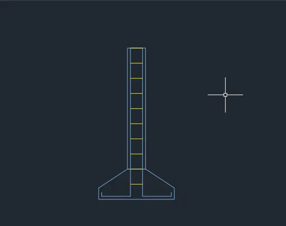
Result:
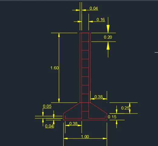
- All dimensions are in meter.
- Footing Drawing – Red Colour
- Dimensions – yellow
Question 3: Drawing the line diagram of a two room bed room building figure in AutoCAD.
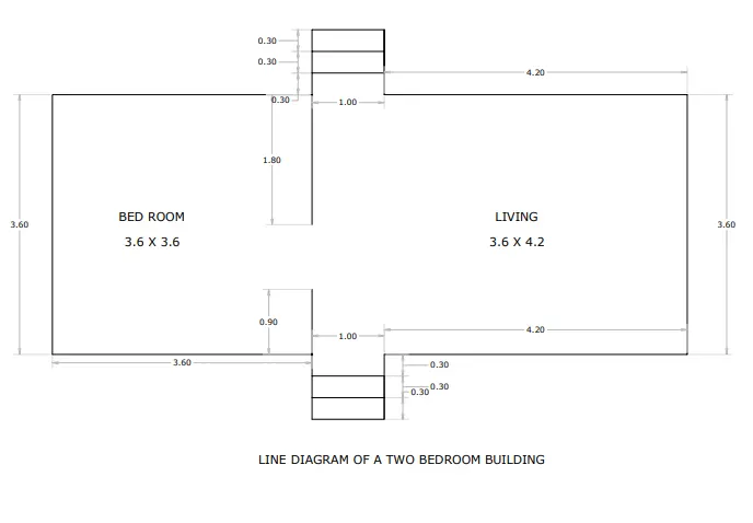
Aim: To draw the figure of C.S. of Line diagram of a two-bedroom building using Auto CAD.
Introduction:
- Line drawings are drawings with details of dimensions and components of building.
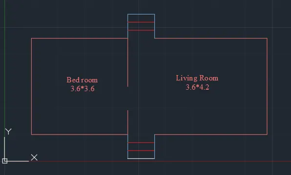
- Two-bedroom building consists of 1x Bedroom, 1x living room and steps in both directions.
Procedure :
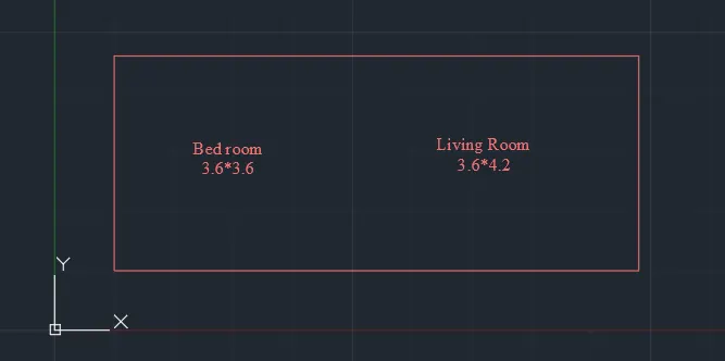
Step.1: Type ‘rec’ in command line or select rectangle from the draw tool bar
- Specify first corner point: let us assume first corner at (1,1) and press enter
- Specify other corner point: Type @8.8,3.6 and press enter
Step.2: Type ‘L’ in command line or select line from the draw tool bar
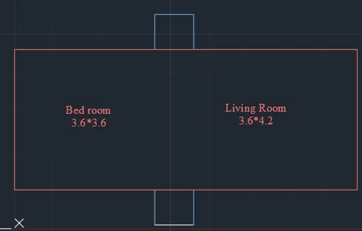
- Specify first point:Type (4.6,1) and press enter
- Specify next point:Type @0, -0.9 and press enter
- Specify next point:Type @1,0 and press enter
- Specify next point:Type @0,9 and press enter
- Press enter to finish the command
Step.3: Type ‘L’ in command line orselect line from the draw tool bar
- Specify first point:Type (4.6,4.6) and press enter
- Specify next point:Type @0, 0.9 and press enter
- Specify next point:Type @1,0 and press enter
- Specify next point:Type @0,-9 and press enter
- Press enter to finish the command
Step.4: Type ‘L’ or line in command line or select line from the draw tool bar
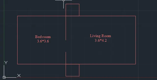
- Specify first point: Type (4.6,1) and press enter
- Specify next point: Type @0,0.9 and press enter
- Press enter to finish the command
Step.5: Type ‘L’ or line in command line or select line from the draw tool bar
- Specify first point: Type (4.6,4.6) and press enter
- Specify next point: Type @0,-1.8 and press enter
- Press enter to finish the command
Step.6:Type ‘O’ and press enter or click offset from the modify tool bar
- Specify offset distance: Type 0.3 and press enter
- Select object to offset: Select the line at the bottom right edge of bedroom and bring curser up an click to offset that line
- Select the last offset line and bring curser up and click to offset that line
Step.7:Type ‘O’ and press enter or click offset from the modify tool bar
- Specify offset distance: Type 0.3 and press enter
- Select object to offset: Select the line at the top right edge of bedroom and bring curser down and click to offset that line
- Select the last offset line and bring curser down and click to offset that line
- Trim the unwanted Drawing.
Result:
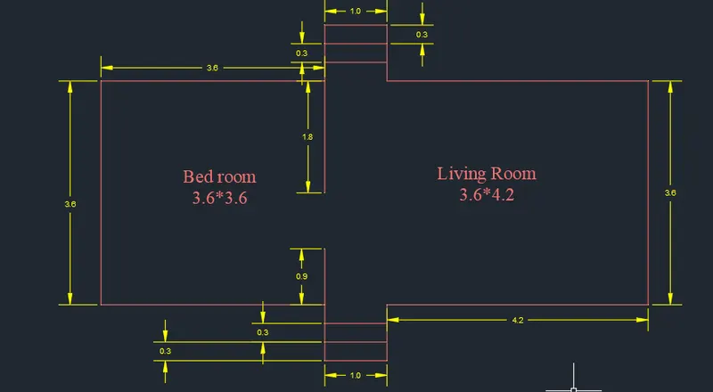
- All dimensions are in meter.
- Dimensions – yellow Colour
Question 4: Drawing C.S of load bearing wallshowing fundamental detail in AutoCAD
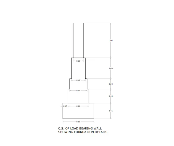
Aim: To draw the figure of C.S. of load bearing wall showing foundation details
Introduction:
- Load bearing wall are walls which take loads from the beams, columns and slab and transfers them to foundation below them.
- Above picture is foundation diagram of a load bearing wall.
Procedure :
Type ‘rec’ in command line or select rectangle from the draw tool bar
- Specify first corner point: let us assume first corner at (1,1) and press enter
- Specify other corner point: Type @0.9,0.45 and press enter
Type ‘rec’ in command line or select rectangle from the draw tool bar
- Specify first corner point: Type (1.15,1.45) and press enter
- Specify other corner point: Type @0.6,0.4 and press enter
Type ‘rec’ in command line or select rectangle from the draw tool bar
- Specify first corner point: Type (1.2,1.85) and press enter
- Specify other corner point: Type @0.5,0.3 and press enter
Type ‘rec’ in command line or select rectangle from the draw tool bar
- Specify first corner point: Type (1.25,2.15) and press enter
- Specify other corner point: Type @0.4,0.6 and press enter
Type ‘rec’ in command line or select rectangle from the draw tool bar
- Specify first corner point: Type (1.3,2.75) and press enter
- Specify other corner point: Type @0.3,1.0 and press enter

Type “tr” or trim in command box or select trim in modify tool bar and press enter
- Select objects: Press enter to select all object
- Trim: Select the objects to be trimmed off from the figure (Select the middle portion of bottom second and third layer of the
footing)
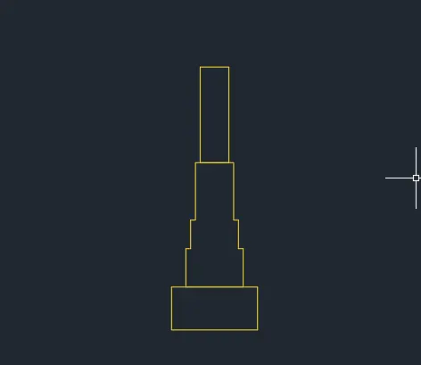
Result:
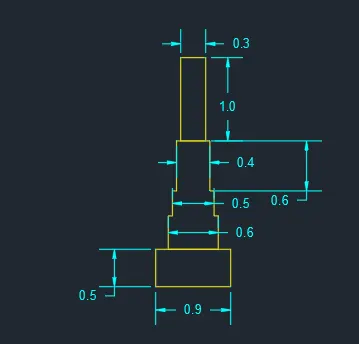
All dimensions are in meter.
Footing Drawing – yellowColour
Dimensions – Cyan Colour
Question 5: Drawing Isometric view of STEPS in AutoCAD
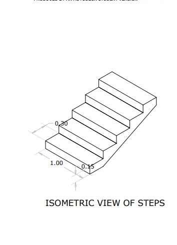
Aim: To draw the figure C5 of Isometric view of steps
Introduction:
- Steps or stairs is a component of a building, which are used to connect different floors or floor at higher level.
- It has a horizontal component called thread and a vertical component called rise. A series of threads and rises form a staircase.
Procedure:
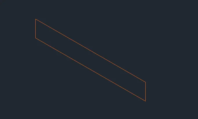
- Go to grid and snap settings and turn on Isometric view.
- Press F5 to change the direction of the isometric view to Isoplane left or change direction in status bar to isoplane left
- Turn on ‘orthomode’
Type ‘L’ or line in command box and press enter
- Specify first point: Type 1,1 and press enter
- Specify next point: Place the cursor to the right of first point and type 1 and press enter
- Specify next point: Place the cursor to the top of last point and type 0.15 and press enter
- Specify next point: Place the cursor to the left of last point and type 1 and press enter
- Specify next point: Place the cursor to the bottom of last point and type 0.15 and press enter or press
- close to the close the rectangle
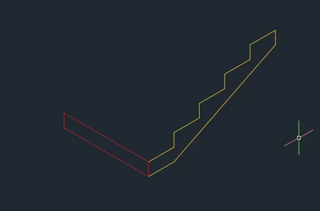
Press F5 to change the direction of the isometric view to Isoplane right or change direction in status bar to isoplane right
Type ‘L’ or line in command box and press enter
- Specify first point: Turn on snap and select the top right edge of the first rise drawn
- Specify next point: Place the cursor to the right of first point and type 0.3 and press enter
- Specify next point: Place the cursor to the top of last point and type 0.15 and press enter
- Specify next point: Place the cursor to the right of first point and type 0.3 and press enter
- Specify next point: Place the cursor to the top of last point and type 0.15 and press enter
- Specify next point: Place the cursor to the right of first point and type 0.3 and press enter
- Specify next point: Place the cursor to the top of last point and type 0.15 and press enter
- Specify next point: Place the cursor to the right of first point and type 0.3 and press enter
- Specify next point: Place the cursor to the top of last point and type 0.15 and press enter
- Specify next point: Place the cursor to the right of first point and type 0.3 and press enter
- Specify next point: Place the cursor to the bottom of last point and type 0.15 and press enter
Press enter twice restart the line command
- Specify first point: Turn on Osnap and select the bottom right edge of the first rise drawn
- Specify next point: Place the cursor to the right of first point and type 0.3 and press enter
- Specify next point: Turn on Osnap and select the bottom right edge of the top step raiser.
Type ‘co’ or copy in the command box or select copy from the modify tool bar
Keep isoplane right turned on
- Select objects: Select all the treads and raisers drawn in the last step and press enter
- Specify base point: Turn on Osnap and select the top right edge of the first rise drawn
- Specify second point: Select the top left edge of first raiser drawn
- Press esc to close the copy command
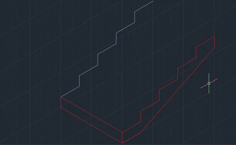
Type ‘co’ or copy in the command box or select copy from the modify tool bar
- Select objects: Select two line connecting the bottom most raiser drawn in first step and press enter
- Specify base point: Turn on Osnap and select the bottom right edge of the first rise drawn
- Specify second point: Select the bottom right edge of second raiser line
- Specify second point: Select the bottom right edge of next raiser line
- Specify second point: Select the bottom right edge of next raiser line
- Specify second point: Select the bottom right edge of next raiser line
- Press esc to close the copy command
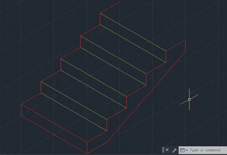
Type ‘L’ or line in command box and press enter
- Specify first point: Turn on Osnap and select the top right edge of the last thread drawn
- Specify next point: Turn on Osnap and select the top left edge of the last thread drawn
- Press esc to close line command
Result:
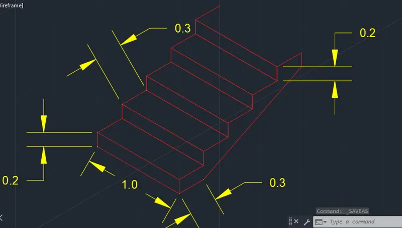
Final end result is as follows
- All dimensions are in meter.
- Steps Drawing – Red Colour
- Dimensions – Yellow Colour
- Threads – 300mm, No- 5
- Raisers – 150mm, No- 5
Question 6: Drawing iSOMATRIC VIEW of GABLE WALL by using AutoCAD.
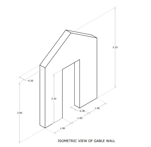
Aim: To draw the figure C6 of Isometric view of Gable Wall
Introduction:
- A wall with triangular portion between the intersecting edges of roof pitches is called gable wall.
- The shape of the gable and how it is detailed depends on the structural system used, which reflects climate, material availability, and aesthetic concerns.
- The combination of wall and the gable at the top is referred to as the gable wall or gable end. While a front-gabled building faces the street with its gable, a side-gabled building faces it with its gutter, meaning the ridge is parallel to the street.
Assumption: As for 3.25 height the slope of gable is very less. Height is assumed as 4
Procedure:
Go to grid and snap settings and turn on Isometric view.
Press F5 to change the direction of the isometric view to Isoplane right or change direction in status bar to isoplane right
Turn on ‘orthomode’
Type ‘L’ or line in command box and press enter
- Specify first point: Type 1,1 and press enter
- Specify next point: Place the cursor to the right of first point and type 3 and press enter
- Specify next point: Place the cursor to the top of last point and type 4 and press enter
- Specify next point: Place the cursor to the left of last point and type 3 and press enter
- Specify next point: Place the cursor to the bottom of last point and type 4 and press enter or press close to the close the rectangle
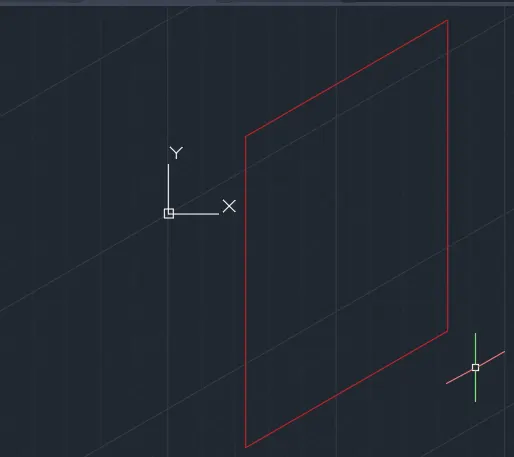
Type Chamfer in command box or select chamfer from the modify tool bar And from options select distance
- Specify first chamfer distance: Type 1.5 and press enter
- Specify Second chamfer distance: Type 1 and press enter
- Select first line: select top left horizontal part of the rectangle
- Select second line: select top left vertical part of the rectangle
Press enter and
- Select first line: select top right horizontal part of the rectangle
- Select second line: select top right vertical part of the rectangle
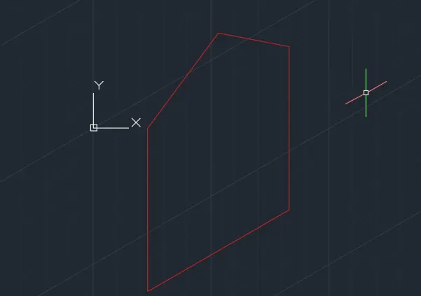
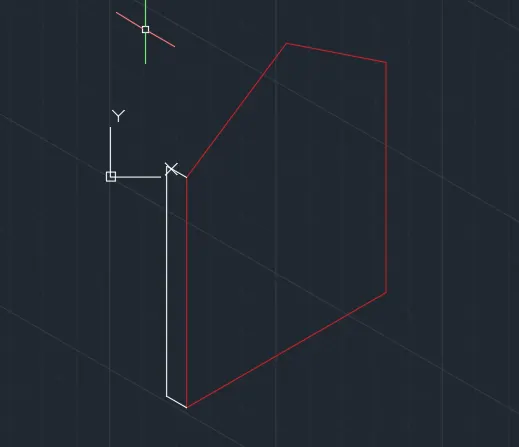
Press F5 to change the direction of the isometric view to Isoplane left or change direction in status bar to isoplane left
Type ‘L’ or line in command box and press enter
- Specify first point: Turn on snap and select the bottom left edge of the rectangle
- Specify next point: Place the cursor to the left of first point and type 0.3 and press enter
- Specify next point: Place the cursor to the top of last point and type 3 and press enter
- Specify next point: Place the cursor to the right of first point and type 0.3 and press enter
- Press esc to close the line command
Press F5 to change the direction of the isometric view to Isoplane top or change direction in status bar to isoplane top
Type ‘L’ or line in command box and press enter
- Specify first point: Turn on snap and select the top point of the gable
- Specify next point: Place the cursor to the top of first point and type 0.3 and press enter
- Specify next point: Turn on snap and select the left side of wall back top end of the wall
Press enter and
- Specify first point: Turn on snap and select the right side of gable end of the wall
- Specify next point: Place the cursor to the top of first point and type 0.3 and press enter
- Specify next point: Turn on snap and select the wall back gable end of the wall
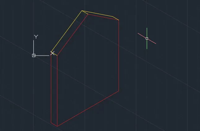
Press F5 to change the direction of the isometric view to Isoplane right or change direction in status bar to isoplane right
Turn on ‘orthomode’
Type ‘L’ or line in command box and press enter
- Specify first point: Type 1,1 and press enter
- Specify next point: Place the cursor to the right of first point and type 1 and press enter
- Specify next point: Place the cursor to the top of last point and type 2.42 and press enter
- Specify next point: Place the cursor to the right of last point and type 1 and press enter
- Specify next point: Place the cursor to the bottom of last point and type 2.42 and press enter
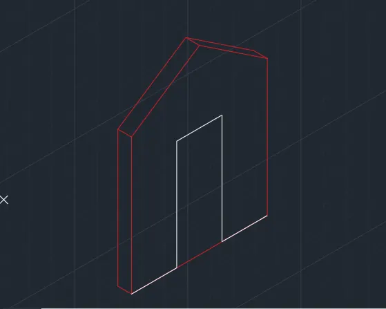
Press F5 to change the direction of the isometric view to Isoplane left or change direction in status bar to isoplane left
- Specify next point: Place the cursor to the left of last point and type 0.3 and press enter
- Specify next point: Place the cursor to the top of last point and type 2.42 and press enter
Type “tr” or trim in command box or select trim in modify tool bar and press enter
- Select objects: Press enter to select all object
- Trim: Select the objects to be trimmed off from the figure (Select the extended wall line at the back of the door and line at the bottom of the door)
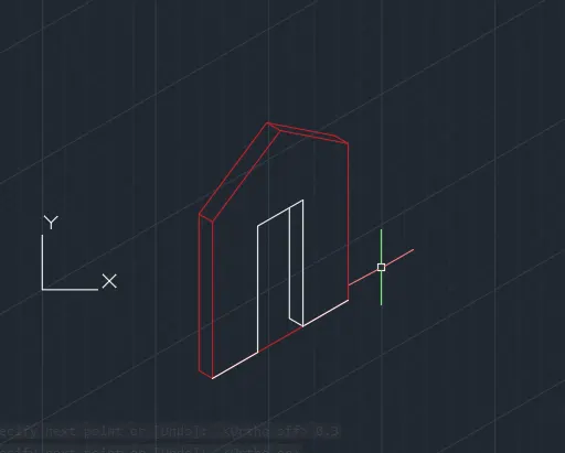
Result:
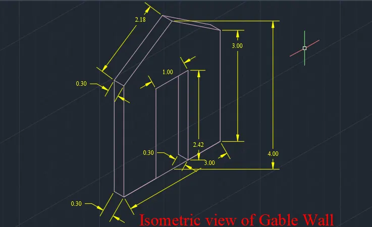
Final end result is as follows
All dimensions are in meter.
Wall Drawing –Blue Colour
Dimensions – Yellow Colour