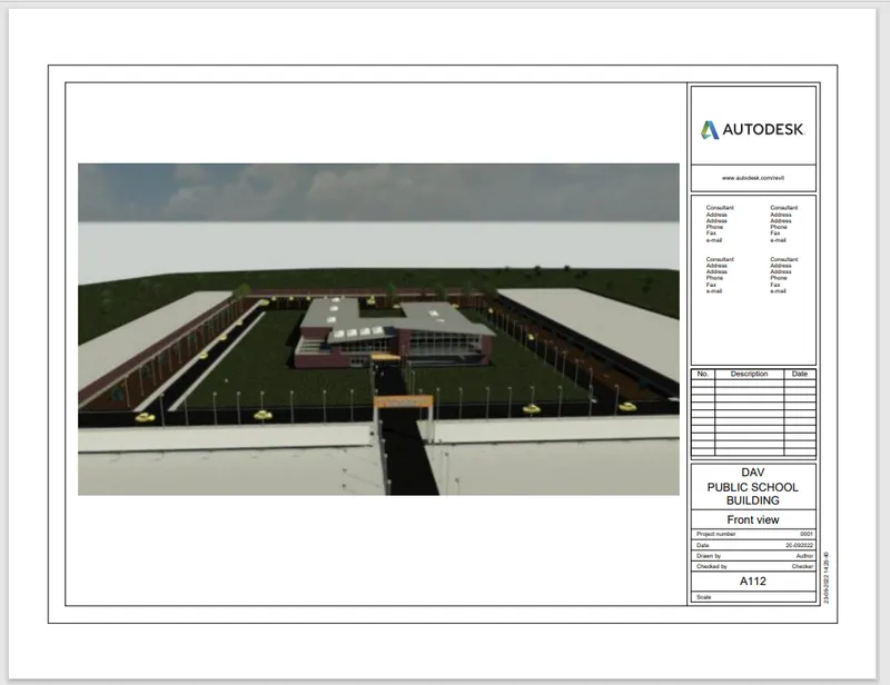
Creating Architectural and Structural model with 3D rendering using REVIT
1) Select the type of structure you want to build from one of the three below:
a. Multi-Unit Residential Apartment
b. Office Buildings
c. School
Aim : To select a structure for modelling in the Revit software.
Procedure :
- Type of structure from above three is school building which is classified as educational building for every 5000 population as per national building code 2016.
- It is G+1 educational building.
Result :
Therefore type of structure is selected as elementary school building for modelling in the Revit
2) Assume reasonable assumptions for geographic and location details for your project modeling. Based on assumptions and type of structure selected identify the modeling requirements from NBC
Aim : To assume reasonable assumption and location details for the project and identify the modelling requirement from NBC.
Introduction :
- National building code provides the standards which should be followed while designing any type of the model.
- It provides minimum standards which should be provided for different type of structure for different locations so that it serves its functionality optimistically without violating environmental and safety measures.
- Likewise for school building NBC provides the minimum standards for area, height, thickness of wall etc.
Procedure :
NBC 2016 requirement for project modelling are as follows
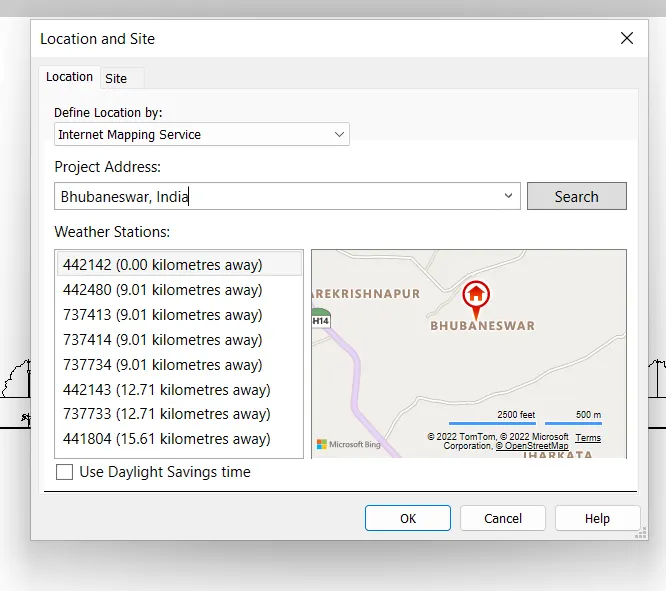
Assume geographic location for project model is Bhubaneswer,odisha India
As per National Building Code ------------->
- Minimum land area per school -----------> 0.4 ha.
- Minimum school building area ----------->0.2 ha.
- Minimum play field area inclusive of the limited parking ------>0.2 ha.
- Minimum ceiling height for educational building ------->3.6 m which is 12’.
- Minimum width provided for staircase [Fire and Life Safety code] -------> 1.5 m
- As the total height of building ----------> 40’6” I e 12.3 [less than 15 m so there is no need to provide the lift.]
Geographic and Location details
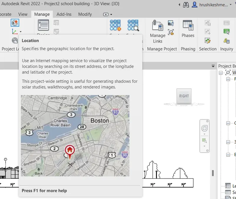
- In Revit software we can set the location go to ----->manage tab ------>location tool of the project location panel.
- By clicking it we can search the area and set the location for the project.
Result :
Therefore, location for building is Set as Bhubaneswer,India.
3) Using the structural model, include the following components based on the type of structure selected
a. Foundation – Isolated / Wall/Matt Foundation
b. Columns
c. Beams Connected to Columns
d. Roof Framing/ Truss
e. Floor / Decks
f. Floor Openings for Elevators and Stairs
Aim : To include the Foundation,Columns,Beams,Roof framing, Floor, Floor opening in structural model in Revit software.
Introduction :
- The components such as foundation, columns, beams, floors are the structural elements of the model which carry various kinds of loads coming on the structure.
- Such structural framing elements can be added in the model using the structural template in the Revit software.
Procedure :
Step 1 :- Architectural Template open
- Open Revit software, select the architectural template.
Step 2 :-Grid creation
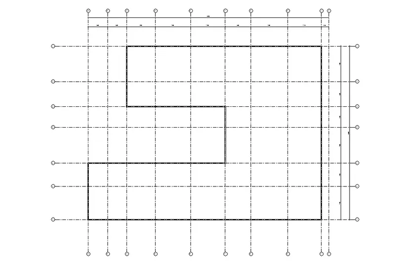
- For making the grid we just creat a rough view of our plan.
- Creation of Grid line as per our plan approximately by selecting the Grid option which is at the top right most side of the software.
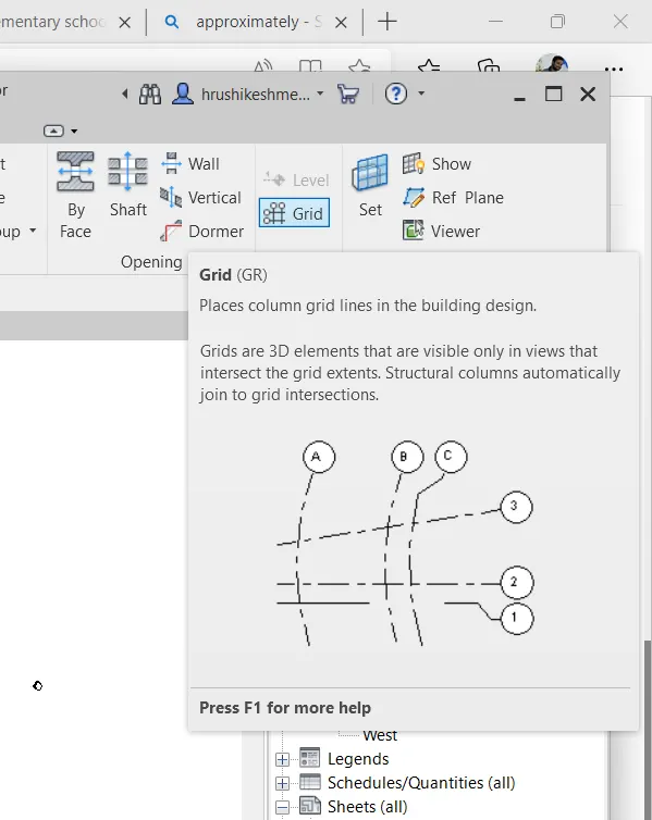
- Now, draw the grid lines as per the approximate plan.
- Grid created----->
- Copy the grid line from Architectural Template to the Structural Template.
- collaborate the project-----> collaborate tab-------->collaborate.----->Within the network------>Save the file as a central file.
- Creat structural Template -->collaborate tab-------->collaborate.----->Within the network------>Save the file as a central file.
- Now, go to Insert option ----> insert the architecture model link into the structural model
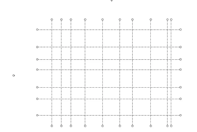
- In the structural template------> collaborate tab ------> copy monitor to copy the grids.
- Choose select link option -------> select link in the window-----> copy the grids both horizontal and vertical.
Step 3:-Grid coordinates Setup
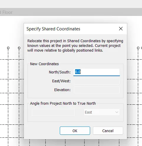
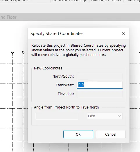
- Now, go to Manage tab------------>select coordinates---------->specify coordinates at a point.

- Then, choose the horizontal grid an then specify the shared coordinate for north/south as 0.
- Similarly specify the shared coordinates for the vertical grid too and set coordinate for East/West as 0.
- Grid creation complited.
Step:-4 Foundation [Isolated] Drawing
- Go to --->site plan view-------> select isolated footing from foundation panel of structure tab------>Placed at the location based on the plan view.
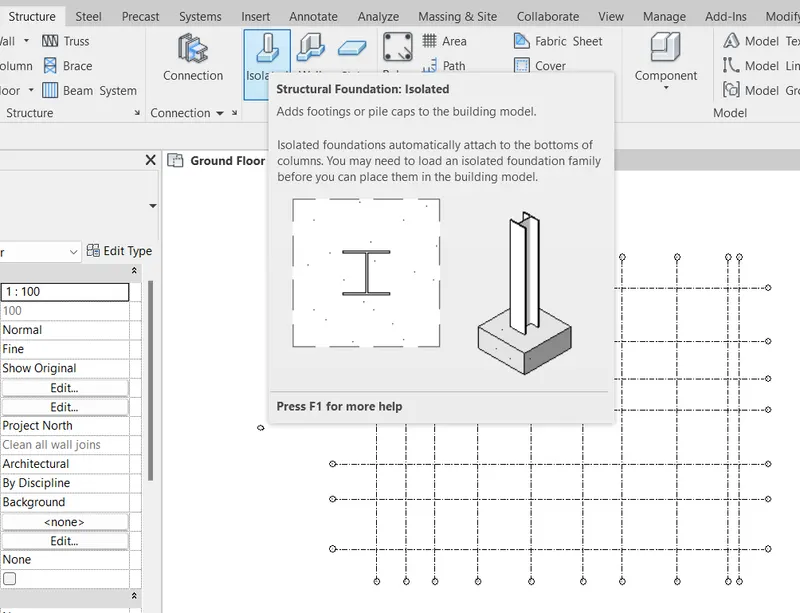
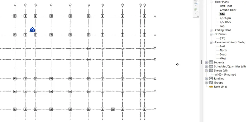
- Foundation creation complited.
Step:-5 Columns Drawing
- Place the columns above each footings.
- Go to Structure-->click on Column---->Place it above the Foundation.
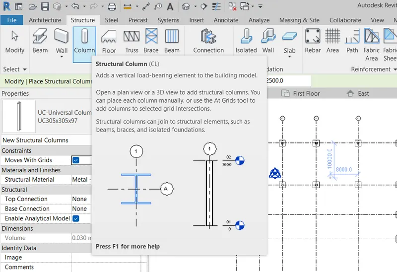
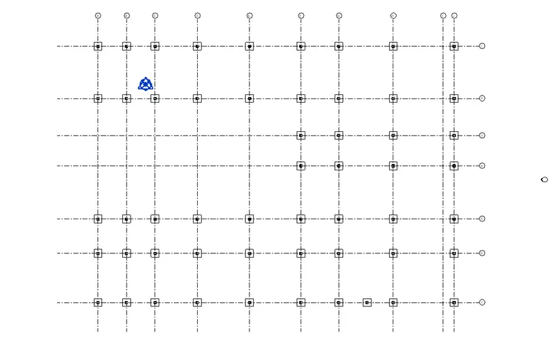
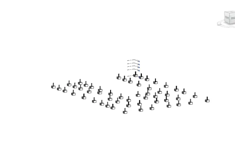
- Column creation complited.
Step:-5 Beams Connected to Columns drawing
- Go to structure tab------> select beam tool----->select concrete beam from property window
- choose beams connect to the column
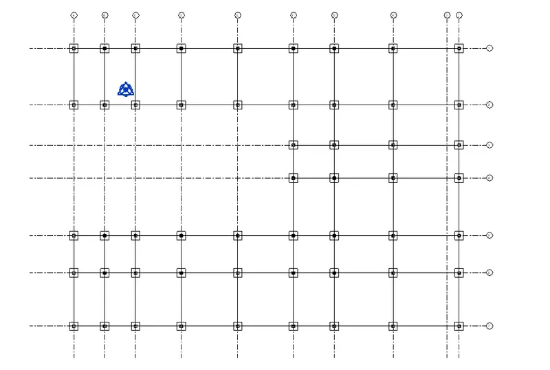
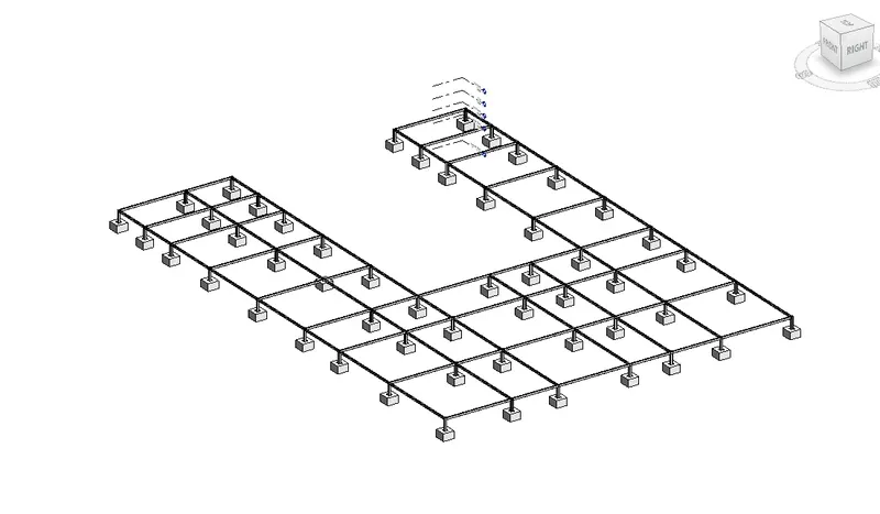
- Beams Connected to Columns creation complited.
Step:-6 Increse the hightof column to the Top level
- Go to the site view .
- Select all by scrolling the mouse.
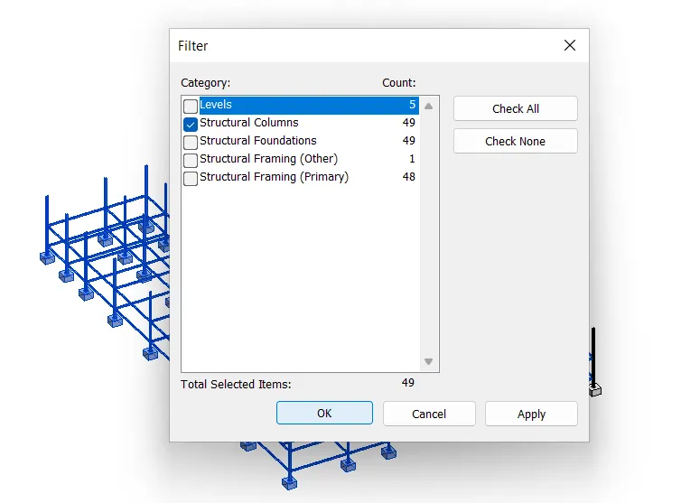
- Go to the filter-------> Select the column only and pess enter.
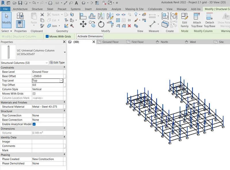
- Change its Top level to ------> TOP from the Property Browser.
- The level of the column changes to TOP.
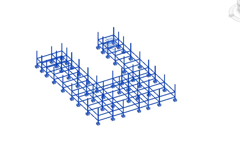
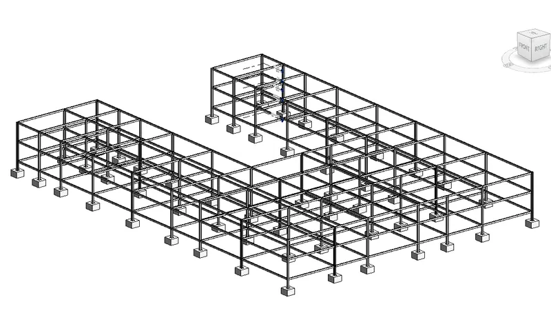
- Creat the Bean for the respective level attach to the column [Top level].
Step:-7 Roof Framing/ Truss creating & Creation of Floor
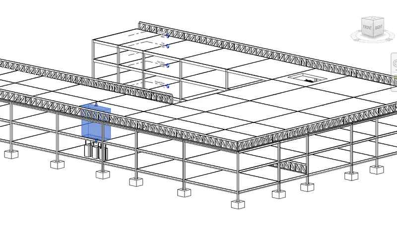
- Creation of Roof
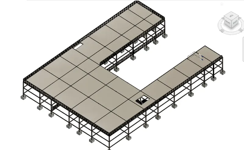
- First to draw the Roof--->go to First Floor plan------->select the Roof tool from structure tab--->select rectangle tool from draw panel and creat the Roof.
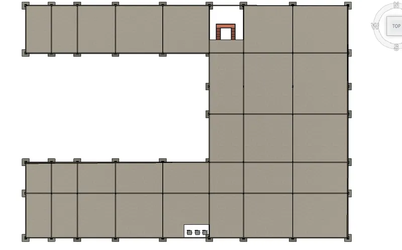
- Creation of Floor
- First to draw the floors--->go toGround Floor plan------->select the floor tool from structure tab--->select rectangle tool from draw panel .
- Draw the roof as shown below by changing the height offset of roof as 4”.
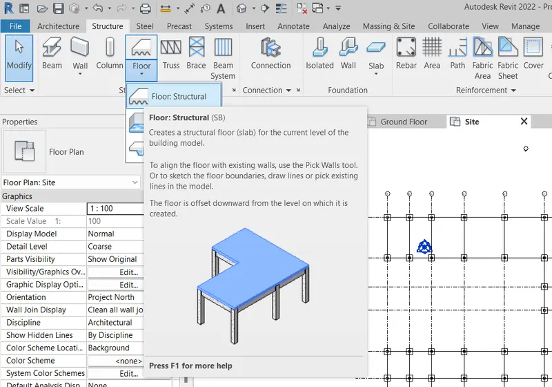
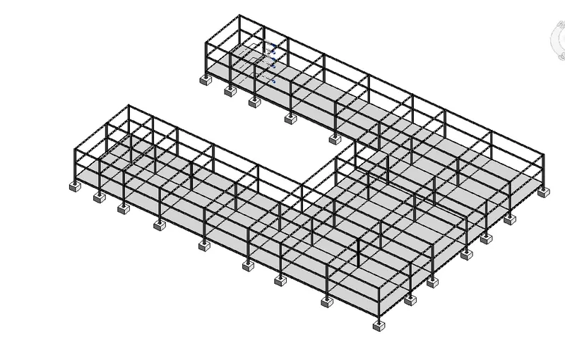
- Similarly we creat the floor for the rest of the level.
- Lets creat the floor for the first floor level.
- Ground Floor Roof:-
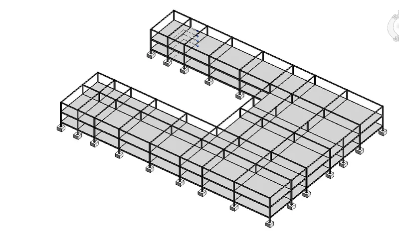
- Hidden View
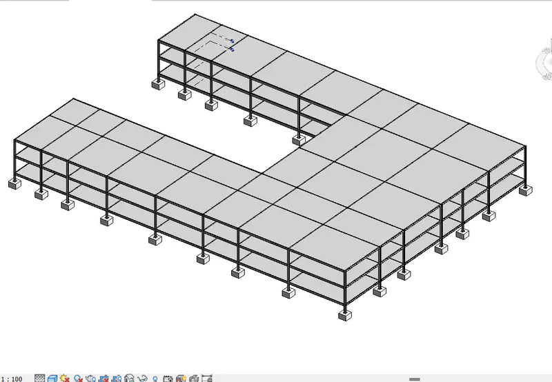
Realistic View :-
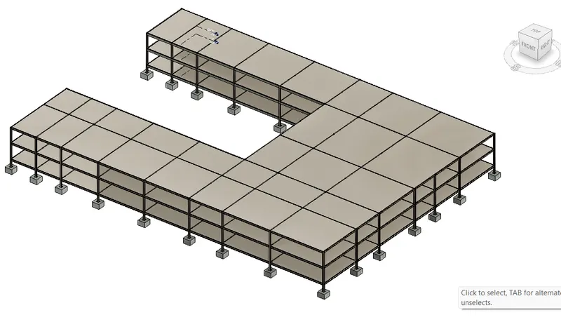
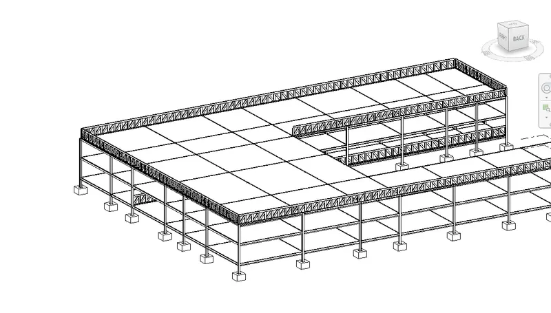
Truss creating
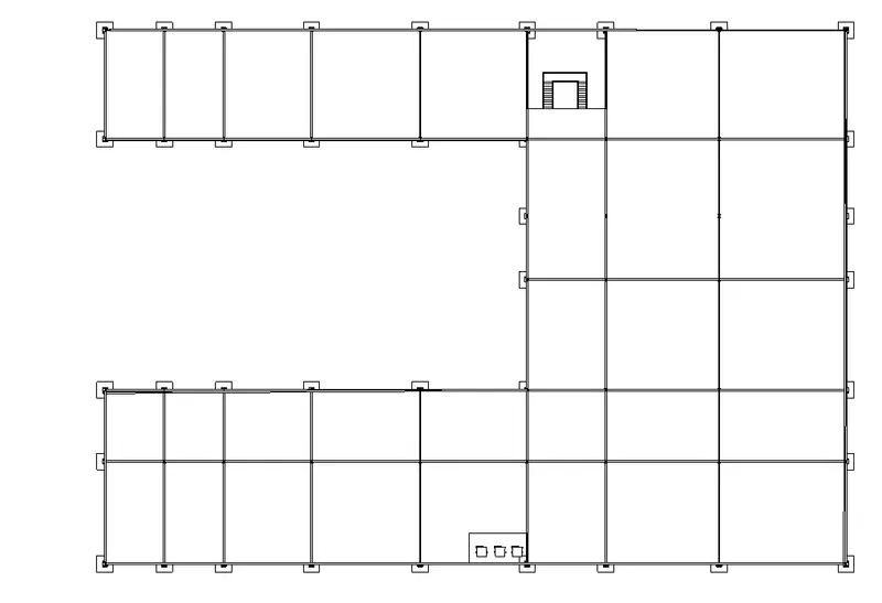
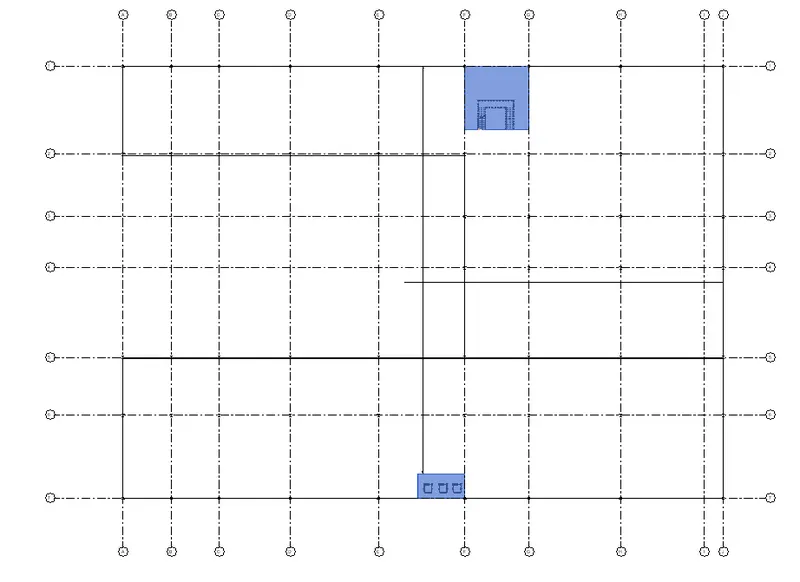
Step:-7 Floor Openings for
- Stairs Floor Openings
- Open the architectural ---->select stair tool -------->select the run and draw .
- Elevators Floor Openings
- Go to insert---->Load Family----->click on Elevator
- Elevators and Stairs creation
- Shaft creation
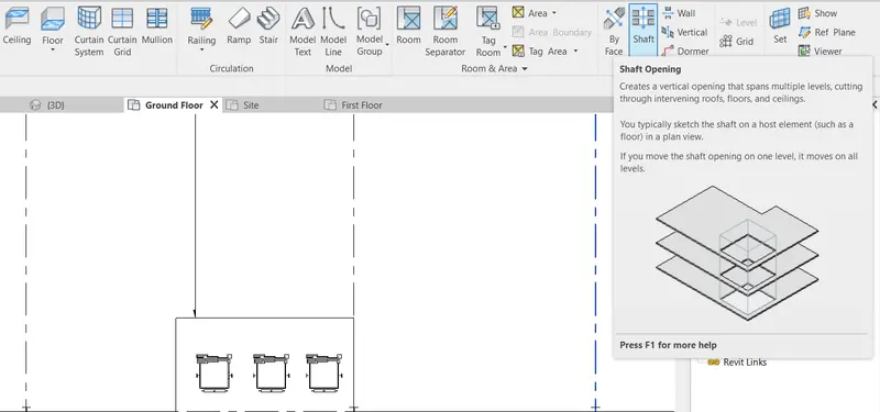
- Shaftt created:-
4) Using the architectural model, include the following components based on the type of structure selected
a. Wall Layout with appropriate material and finishing
b. Exterior facade with fancy finish
c. Interior partition walls to size rooms
d. Components to add details to a room ( Desk, Chair, Lighting, Plumbing fixtures)
e. Add components such as stairs Elevators
f. Have at-least one side of the building with curtain walls and glass panels
g. Include interior and exterior lighting fixtures
h. Place proper topographic components from outside ( Trees, Parking, Plants) to add details to the model
Aim : To include the architectural components such as walls, exterior facade with fancy finish, partition walls, components adding details to the model, stairs, interior and exterior lighting fixtures, topographical components outside the model in the Revit software.
Introduction
- Architectural elements such as walls, doors, windows etc., can be added in the model using the architectural template.
- Revit is a BIM software where we can add the minor details to make the model more realistic to utilize or make more efficient space management without making any compromises in the future.
- Such details may include desk, chairs, lighting etc.
- In Revit we can also add the topographical features which can be helpful to estimate the excavation or cutting cost even before starting the project.
Procedure :
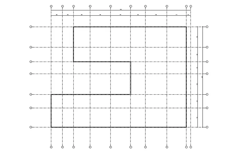
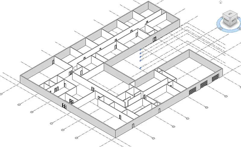
Step 1 Ground Floor Creation{ Creation of Extetior wall }
- Open the architectural file from home page of Revit software to add the architectural components.
- Select the walls tool from architecture tab--------->select wall type generic 12” [property window]
- Edit Type----->Exterior wall---->draw the walls at required position to creat the ground floor.
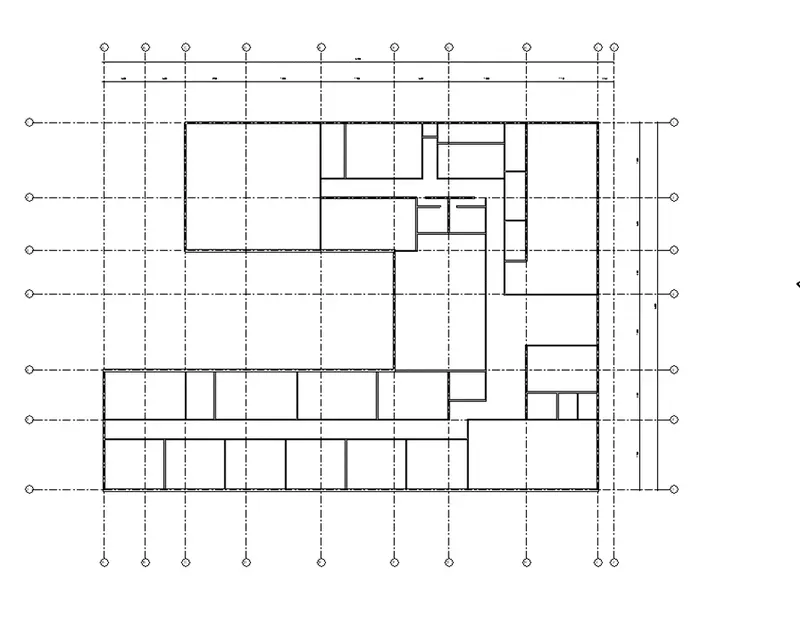
Step 2 Creation of Interior [Partition] wall
- Select the wall--------->Select Wall Generic 8 "
- go to edit type from properties window----->duplicate wall type
- Rename as Partition wall------> and select the wall material as brick common------> select ok
Step 3 Creation of Dooor
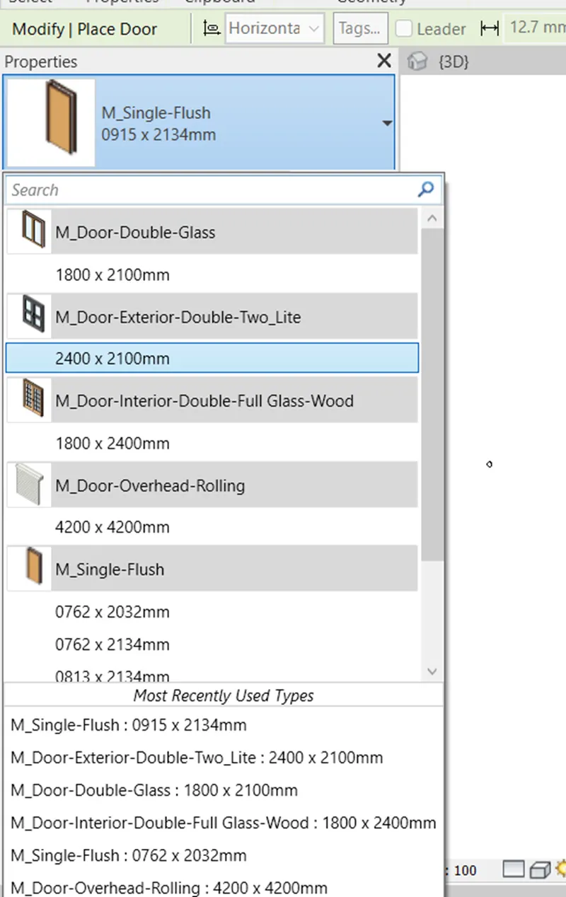
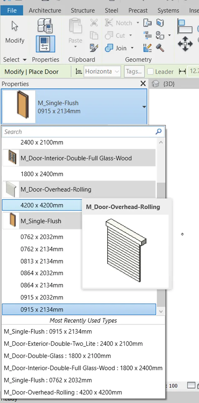
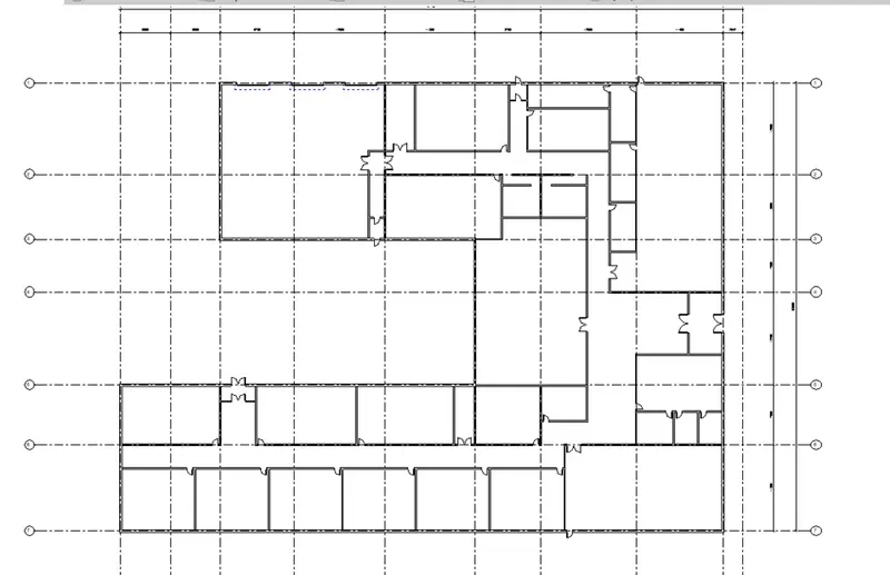
- Go to architecture tab-----> select door tool from build panel---->select load family from mode panel of place door tab and place the doors at required position as shown below.
- Also use a overehead Rolling Placed at the playground for going outside.
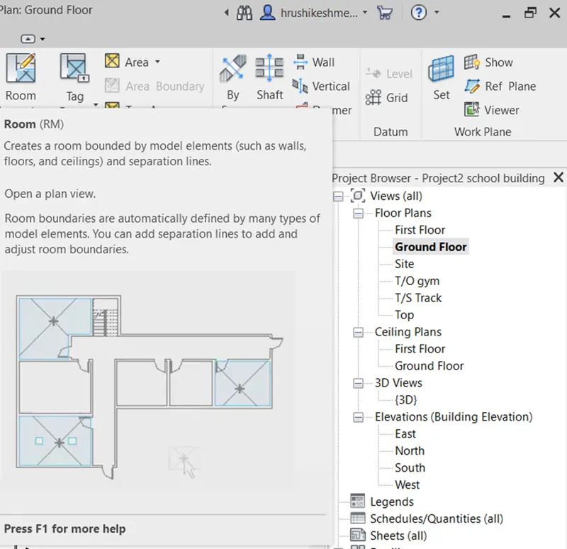
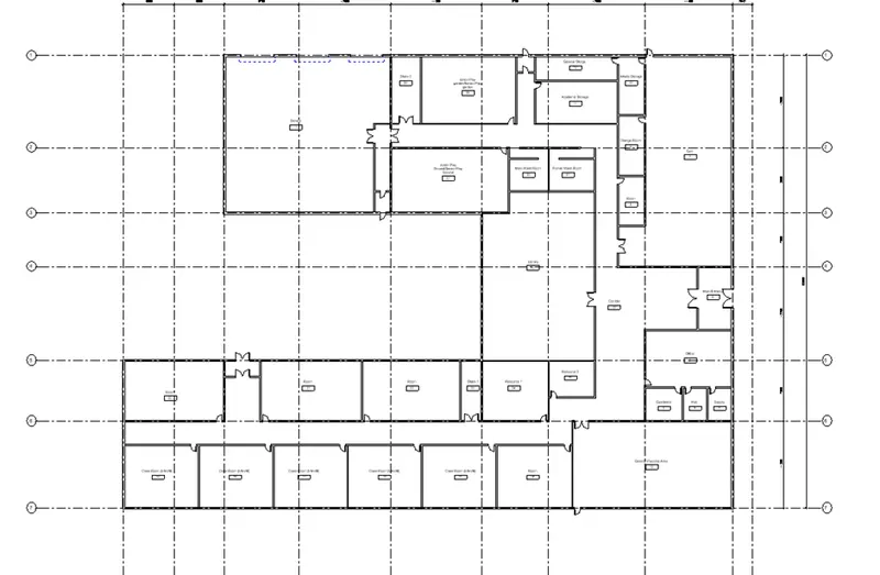
Step 6 Taging Room
- Go to Structure------>Click on Room------>Tag alll the Room in the Ground Floor
Step 7 Creating First Floor
- Creation ofExterior wall
- Open the architectural file from home page of Revit software to add the architectural components.
- Select the walls tool from architecture tab--------->select wall type generic 12” [property window]
- Edit Type----->Exterior wall---->draw the walls at required position to creat the first Floor.
- Creation of Interior [Partition] wall
- Select the wall--------->Select Wall Generic 8 "
- go to edit type from properties window----->duplicate wall type
- Rename as Partition wall First floor------> and select the wall material as brick common------> select ok
- Insert Door
- Go to architecture tab-----> select door tool from build panel---->select load family from mode panel of place door tab and place the doors at required position as shown below.
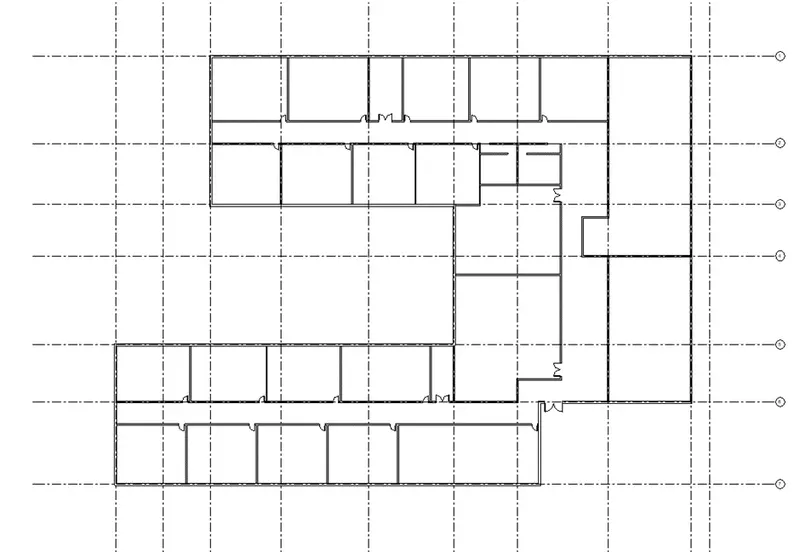
Taging Room in the first floor
- Go to Structure------>Click on Room------>Tag alll the Room in the Ground Floor
Step 8 Components addition
- For adding the components such as desk, go to architecture tab, select the component tool from build panel, select load family option and load the desk and add it in the model at required position as shown below.
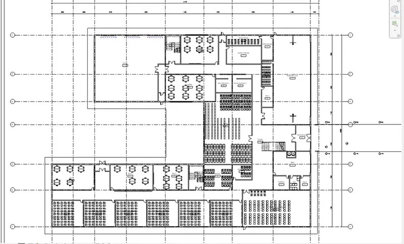
- Also add component for the first floor.
Step 9 Creation of stair case and Elevator
- Go to Architecture tab--------->click on stair----->Creat it at the Stair case 1 and Stair case 2 room that we created.
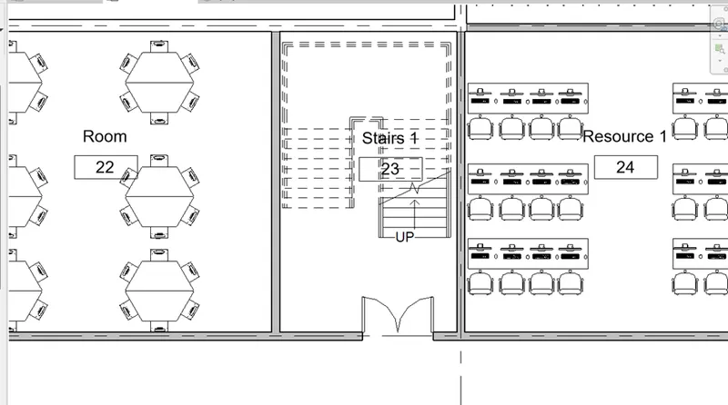
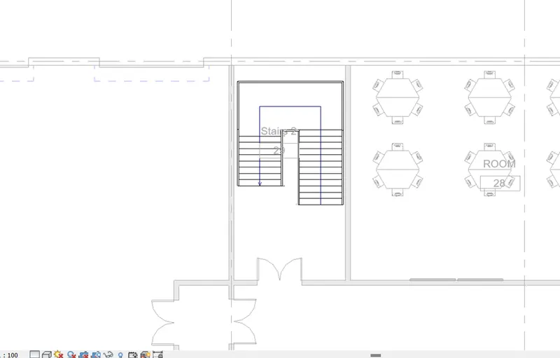
- Another Stair case placed at the entrance of the School.
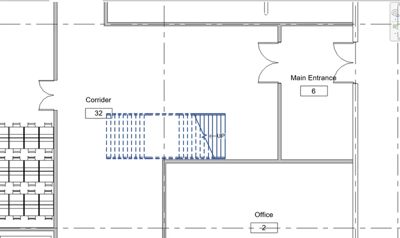
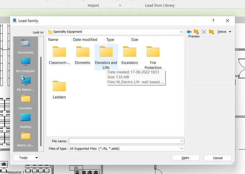
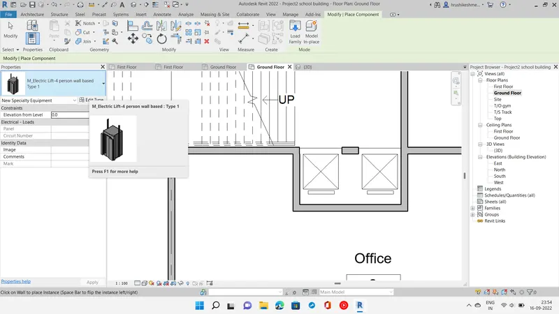
- Insert Elevator
- Go to Insert------------>Load Family--------->insert elevator
- Insert eleveator in the elevator Room
Step 9 Creation of Floor for both ground floor and First floor
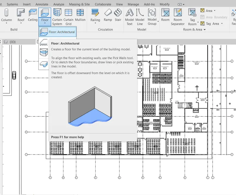
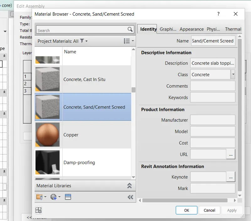
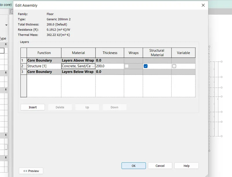
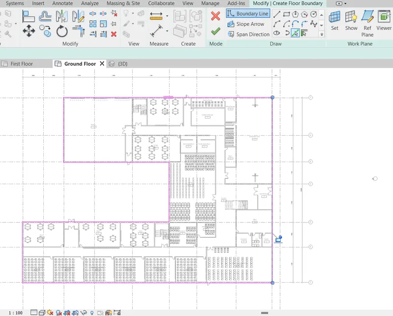
- Go to Architectural ---------->Select Floor
- Click on Edit type command--------->edit material
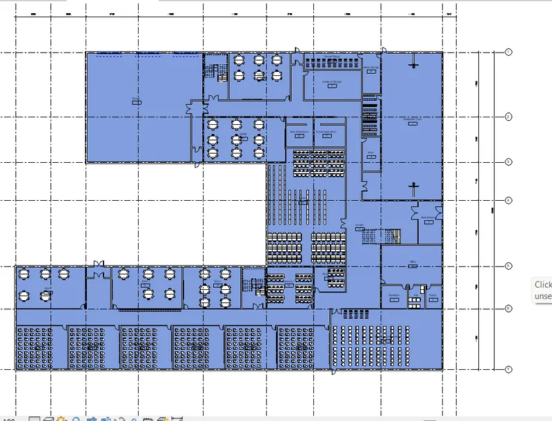
- click pick line option---->Draw the outer Floor line and Creat the Floor.
- Floor creation for ground Floor
- Floor creation for First Floor
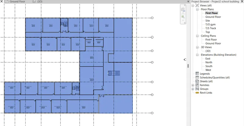
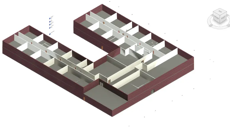
Realistic view:-
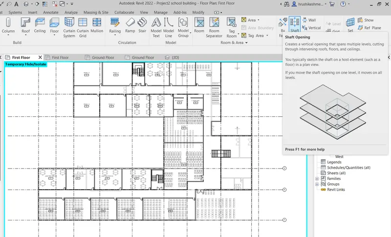
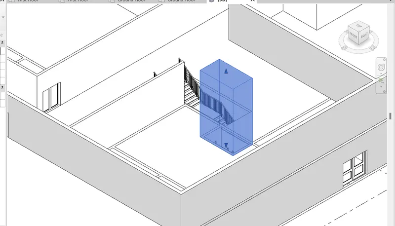
Step 9 Creation of Shaft
- Go to Architecture ------->Select Shaft
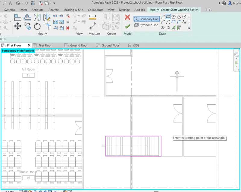
- Then go to modift tab and select rectangle component and Draw the shaft
- Shaft Draw for Main entrance Stair case
- Shaft Draw for Staie case 1
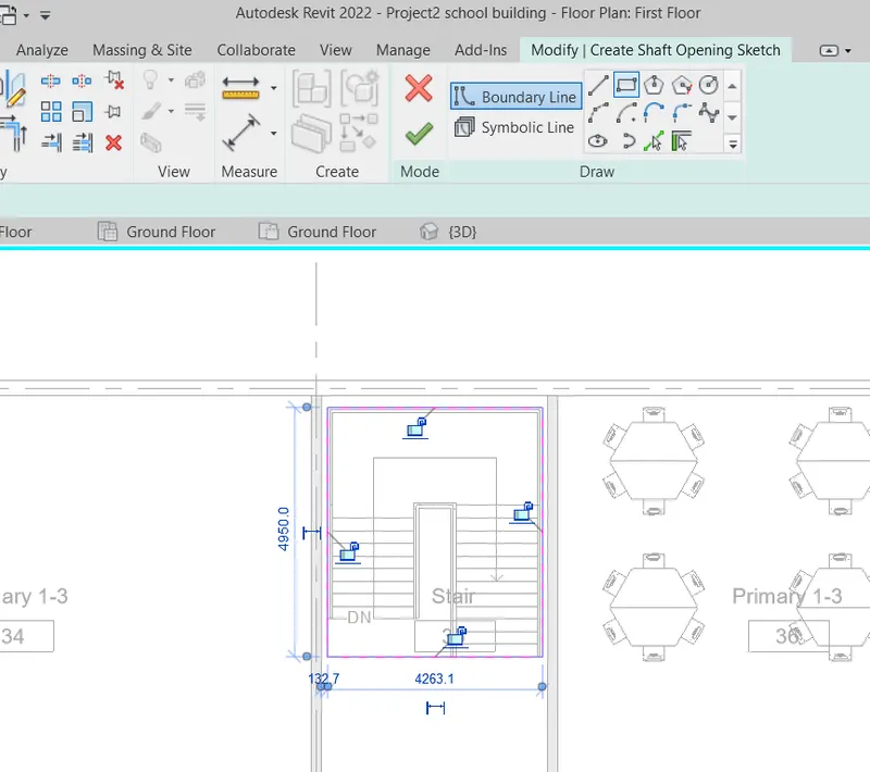
- Shaft Draw for Staie case 2
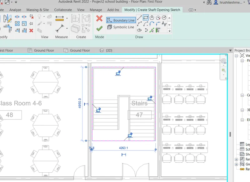
- Shaft draw for Elevator
Step 10 Creation of Roof
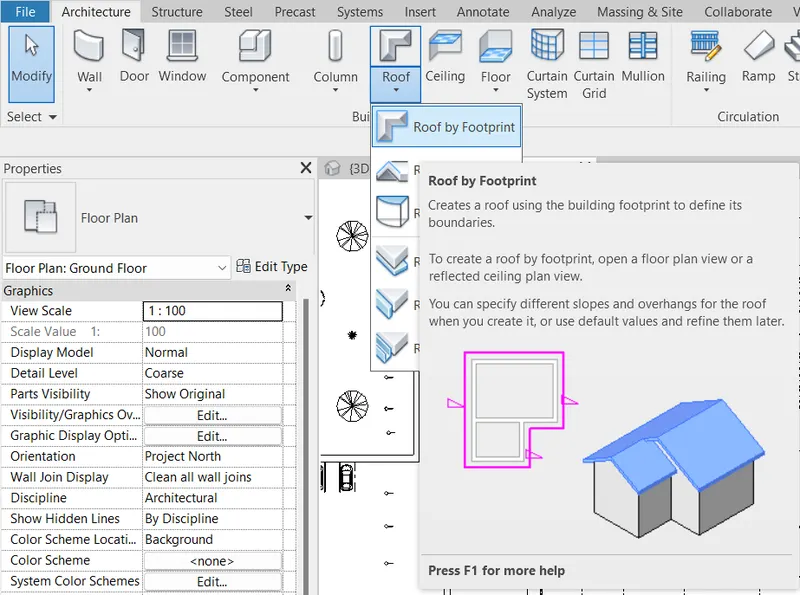
- go to First Floor plan
- Go to Architecture--------->Roof
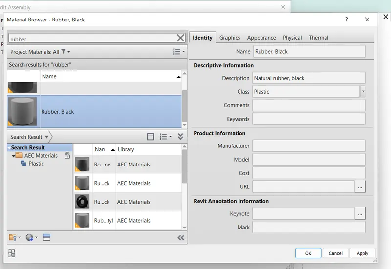
- Edit Type------->Choose the Material -------->Roof by Foot print
- Go to modify-------->Select pick line option------>Select all the boundary line -------->Click on Finish
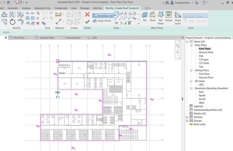
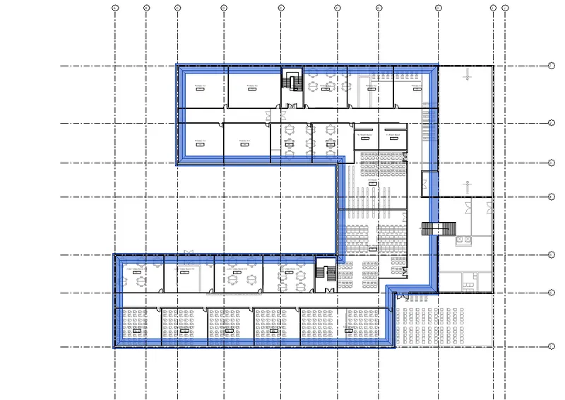
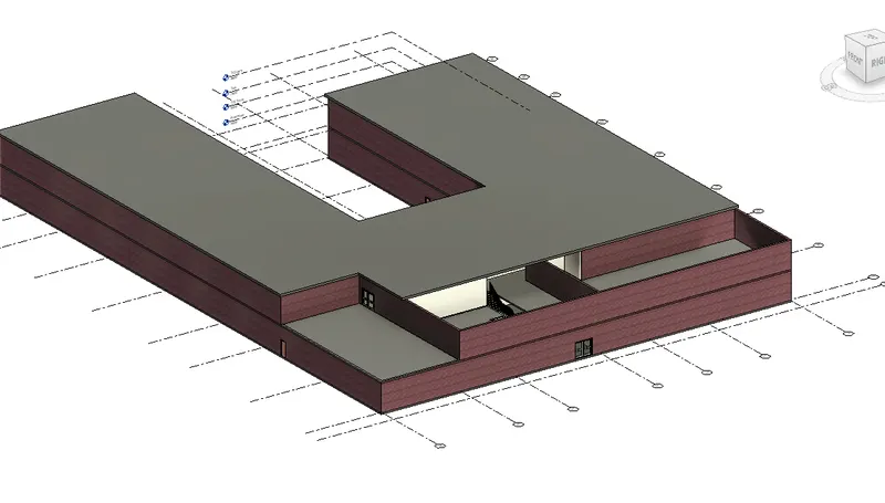
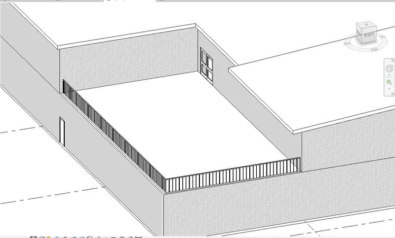
Step 11 Creating the Railing For the Garden
- Creating Railing for the Garden which are created at the first floor
- Go to Architecture------->Railing------->go to modify---->Select line
- Draw the Line at the required place.
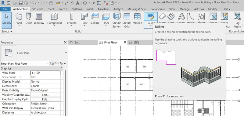
Step 12 Creating the curtain wall
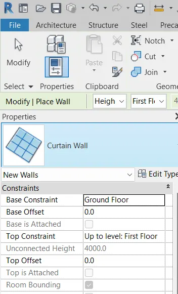
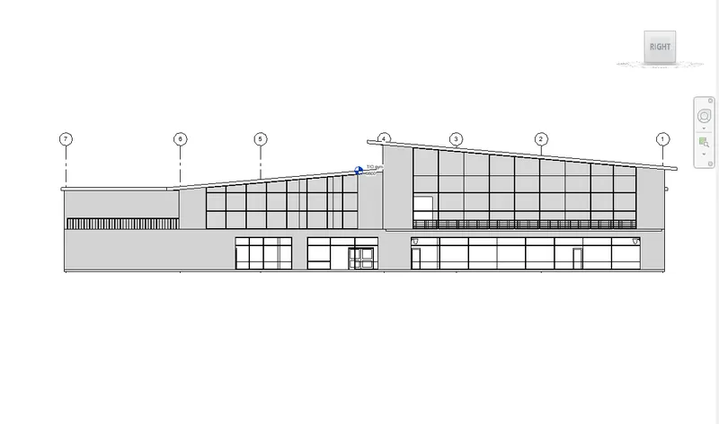
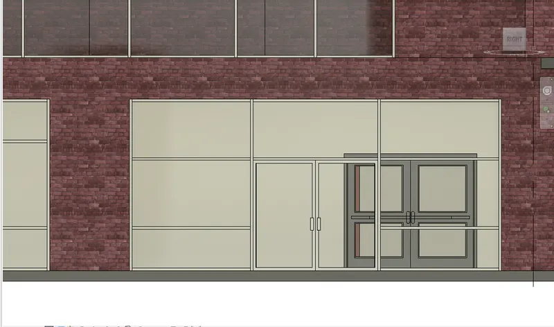
- For adding the curtain system, select the front wall which is required to make as curtain wall, select drop down of basic wall type, and change the wall type toCourtain wall as shown below.
- Select the First floor level--->Select the wall where the curtain wall required------>go to modify--->cut--->make the Curtain wall.
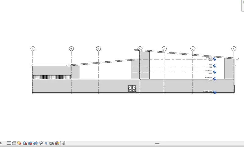
- Select the curtin grid and make the opening Perfect
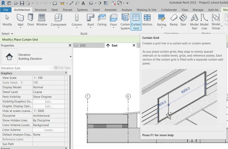
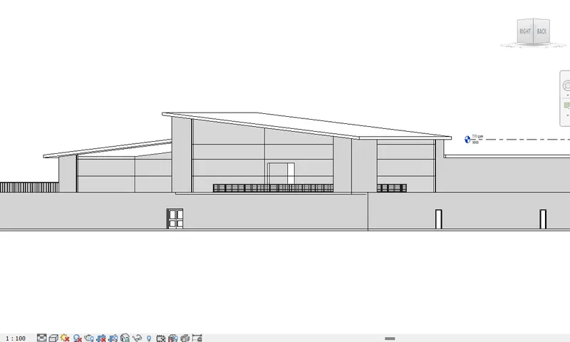
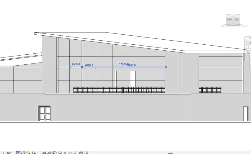
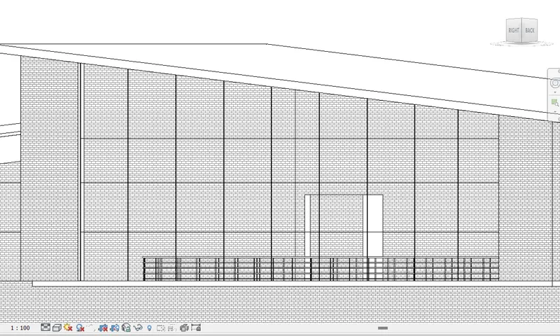
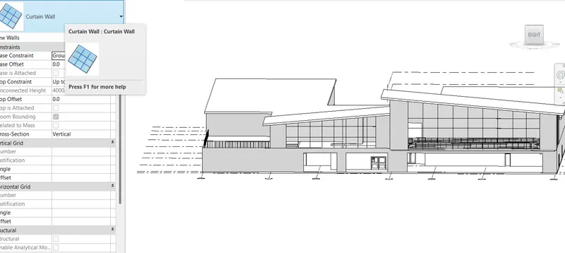
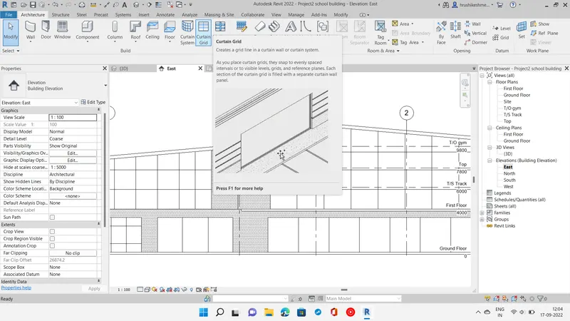
- Then click on Mullion.click all the cunter grid.
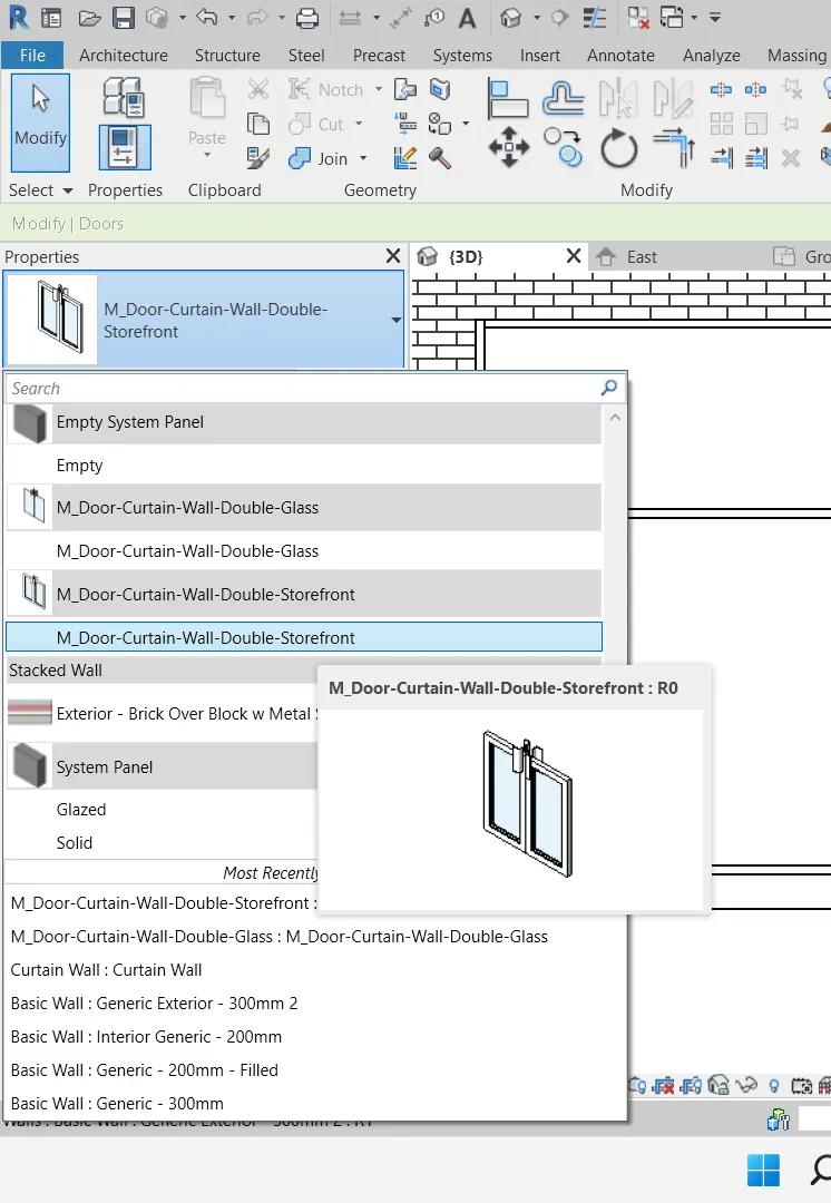
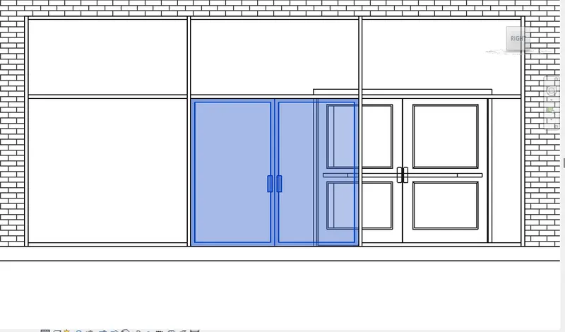
- Insert the Main Door in the curtain wall.
- Realastic View
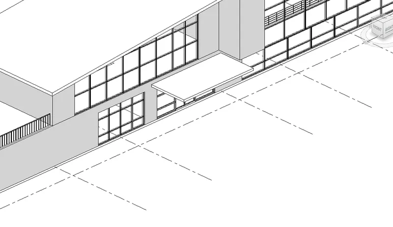
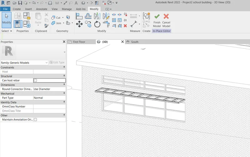
Step 12 Creat a model for Cantiliver chaja above the Main door
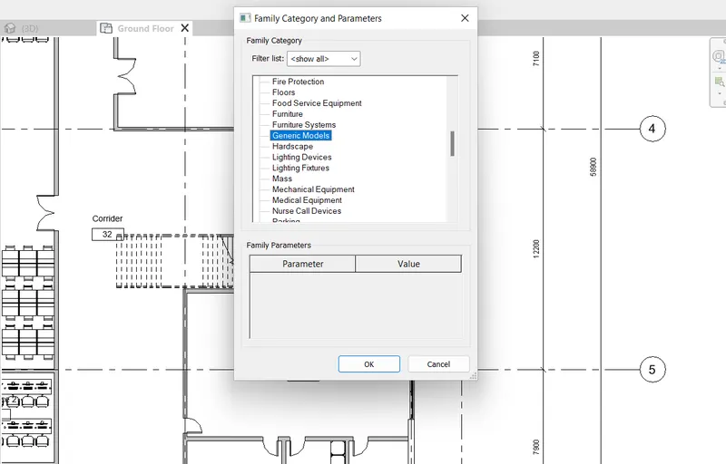
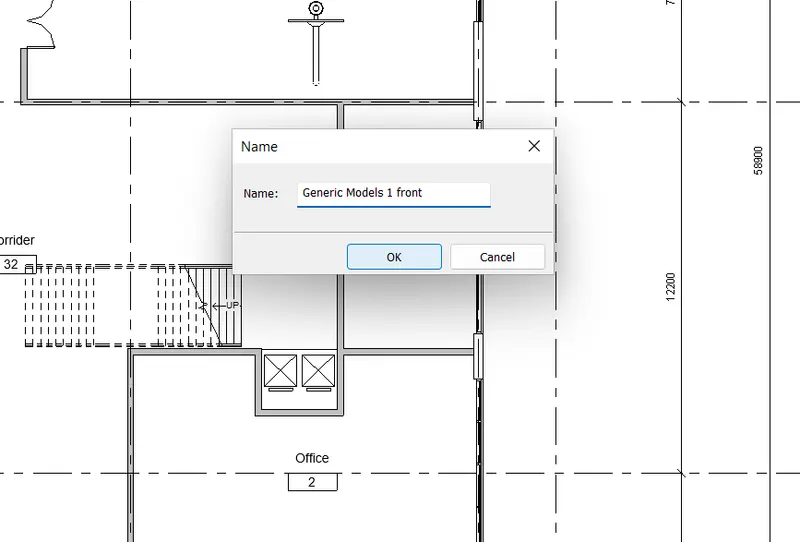
- Go to the Component----->then select Made in place--->Select the Generic model--------->Creat model
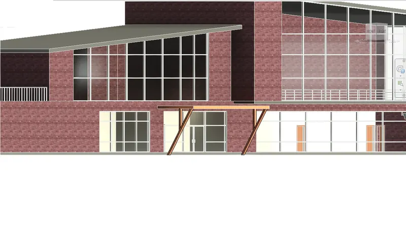
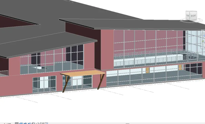
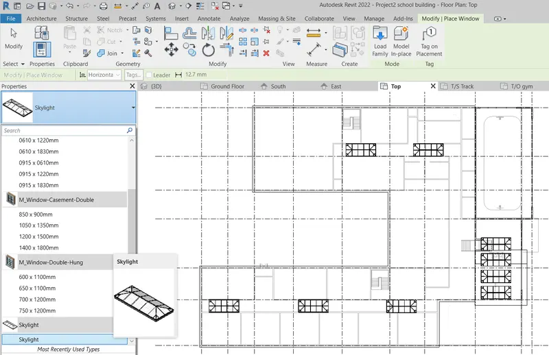
Step 13 Creat skylight
- Go to Insert-------->load family----->Select skylight type-----> Placed as per the requirment
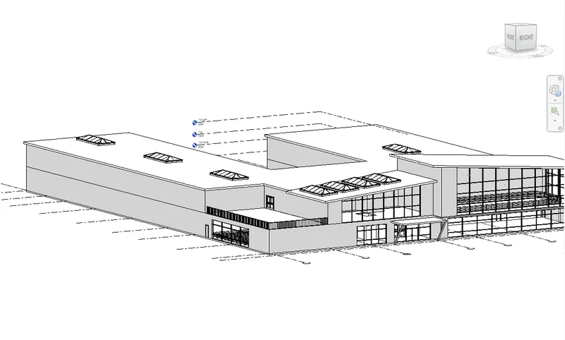
Step 13Creat curtain wall for window
- Go to architecture--------->Wall --------->Select Curtain wall------------>Draw the wall at required window
- Draw all the curtain wall at required place.
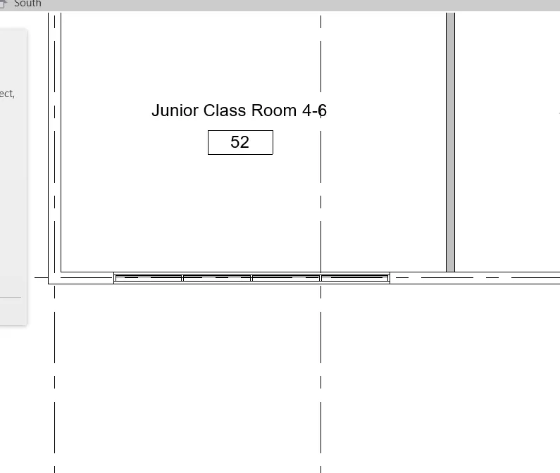
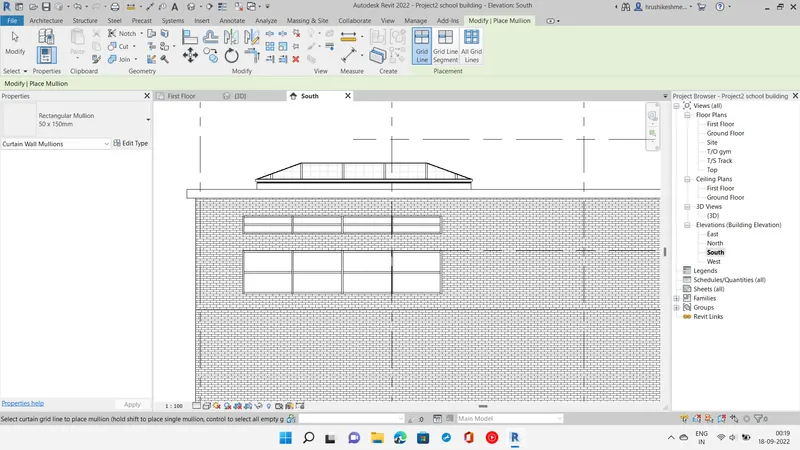
- Creat a model space for the chaja over all the curtain wall creating.
- Change Edit type-------->Change the material as copper.
- Set the model.
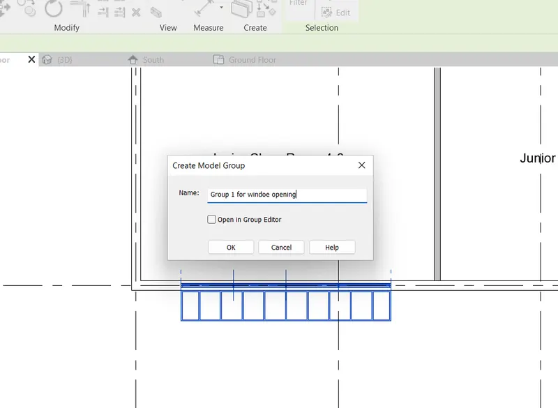
- Creat the Group.
- Draw Group as per requirment.
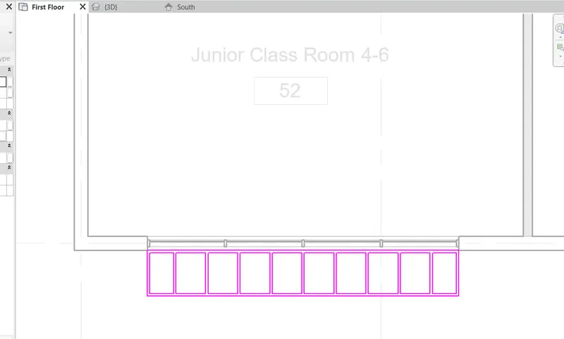
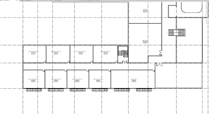
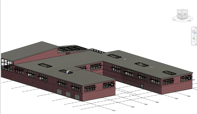
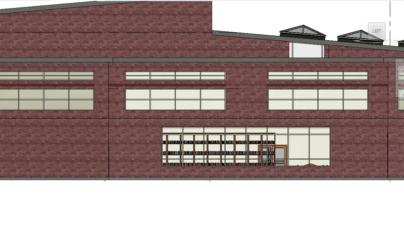
- Also creat the curtain wall for ground floor.
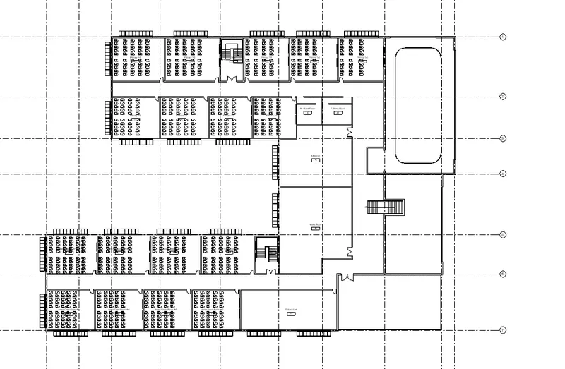
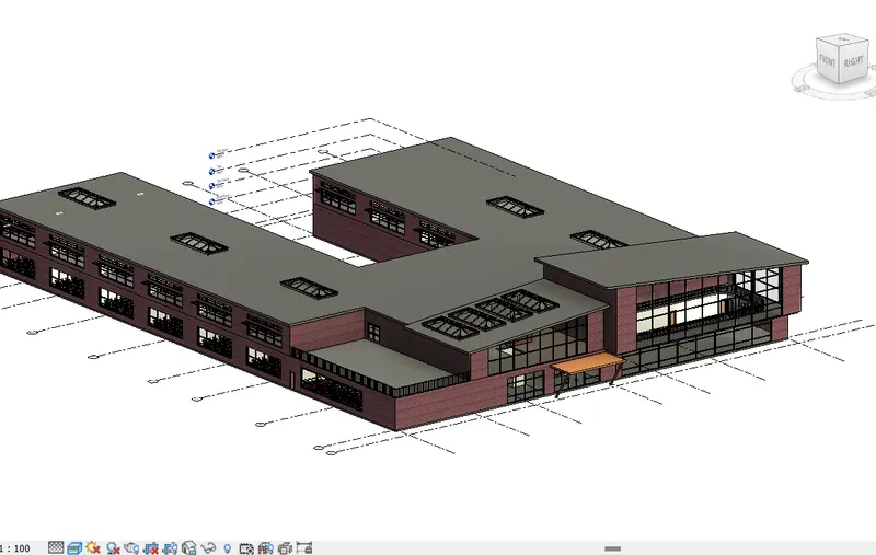
Step 14 Creation of Toposurface
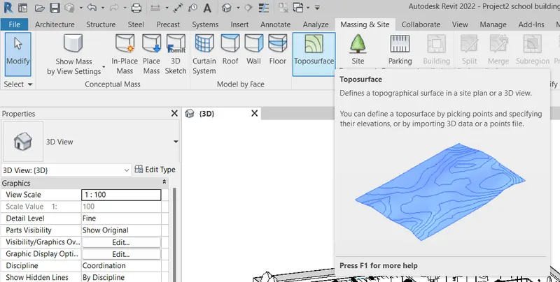
- For adding the topographical components, go to massing and site tab, select the Topo surface
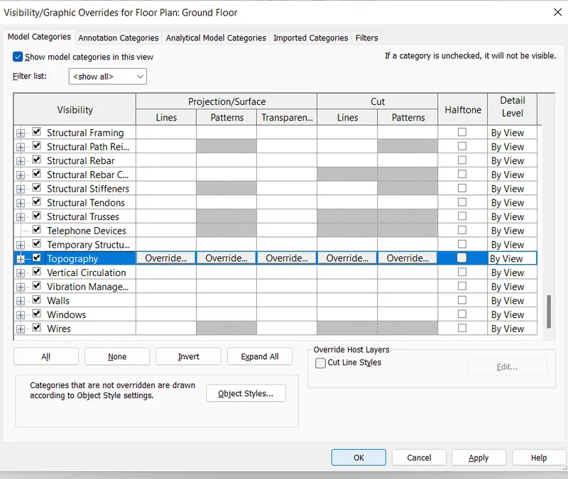
- If the TopoGraphic elements are not visible then --------->Click on Vg----->tik mark on topography to visible
- Change Edit type and chane the Material as Grass.
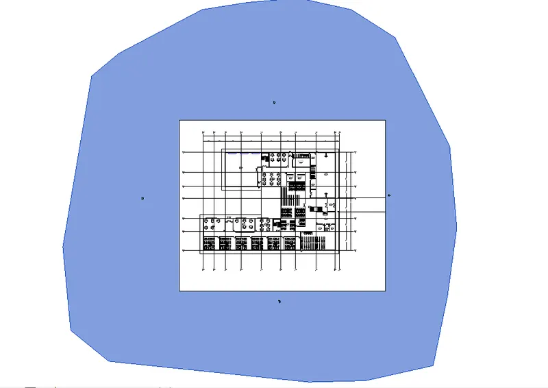
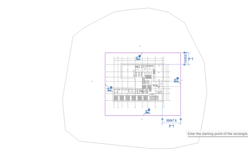
- For drawing the building pad, select the building pad tool from modify massing and site tab, select rectangle tool from draw panel and draw the rectangular building pad as shown below.
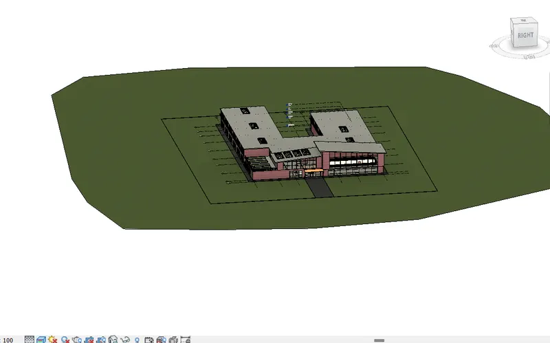
Step 15 Creat Street
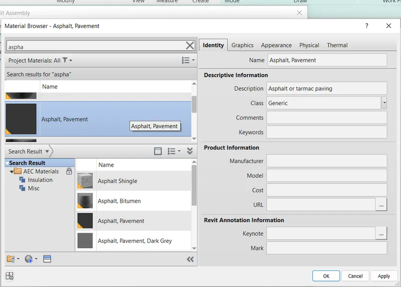
- Select the Floor to creet the Street.
- Select Edit type and change the meterial as Asphalt.
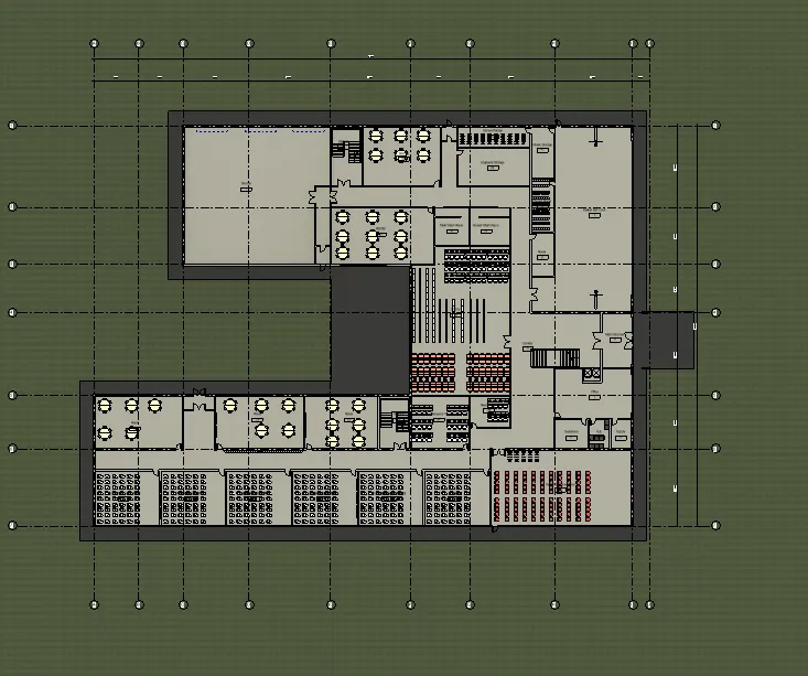
- Select floor--->change material to Earth------>then creat the outer boundary.
- Go to load family----------->Add Plant
- Goto Add component-------->Add Plant at required place
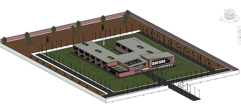
Step 16 Creat Faculty Parking
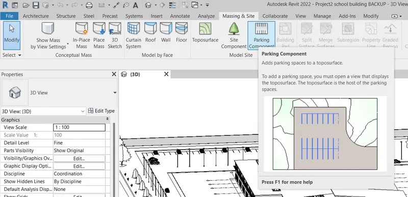
- Creat main Gate and Parking facility
- Go to Massing and side----------->Click on Parking ------->Draw the parking facility at the respective place as showing below
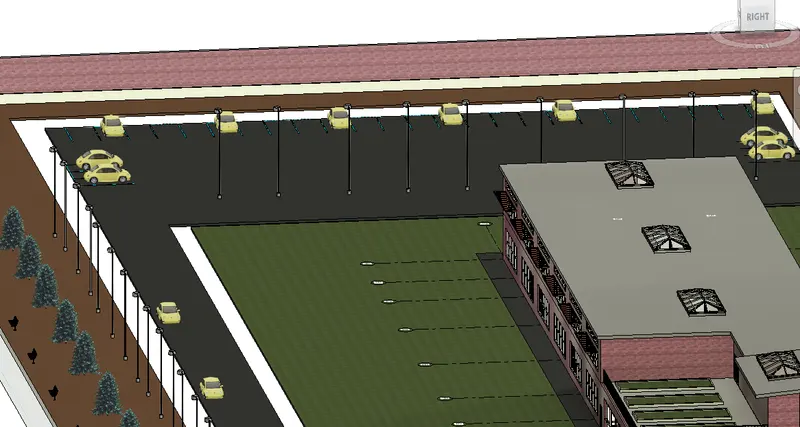
- Creat main Gate
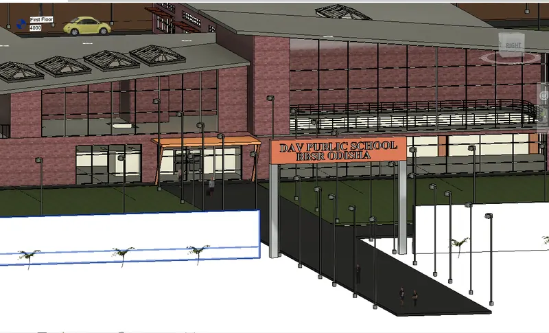
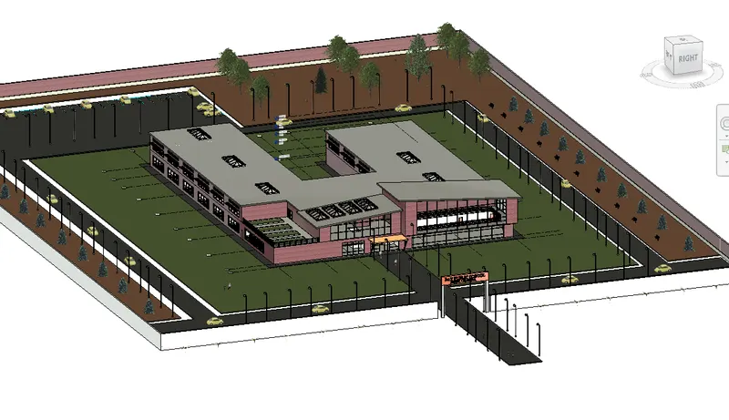
Final Result:-
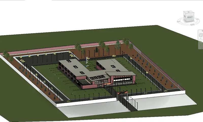
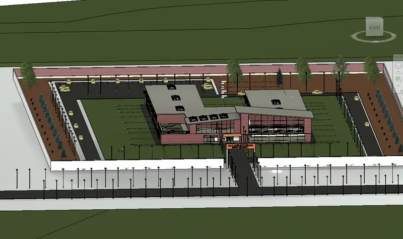
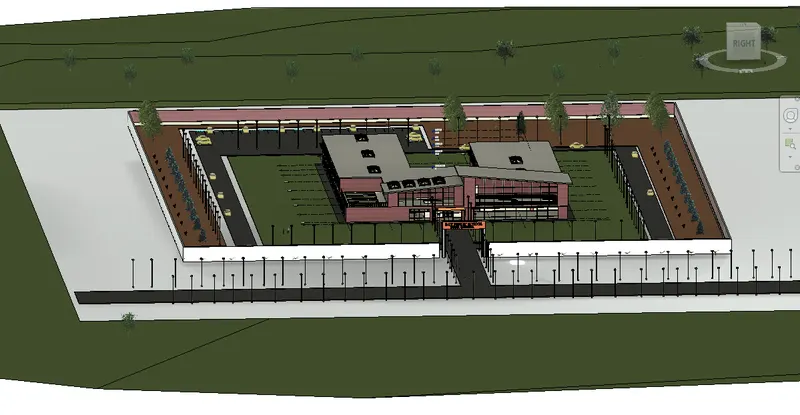
5) Provide a set of drawings in an architectural and structural model to list the following details with categories and appropriate sheet templates included
a. Floor Plans with Annotations
b. Elevations
c. Sections
Aim : To provide set of drawings in structural and architectural model to list the floor plans with annotations, elevations and sections details in sheet template in Revit software.
Introduction :
- To communicate with the help of drawing with the workers who actually execute the construction of the project on site the annotations such as dimensions are provided and rooms are tagged with their respective names so that it will be executed as per the designed plan.
- In Revit dimensions of lines are measured with help of the aligned or horizontal tool of the annotate tab.
Procedure :
Step 1 Room tag
- Open the architectural template file to give annotation ---->dimensions to the plan
- Go to annotation tab----->select linear or aligned tool ----->Give dimensions to the plan view
- Room tagging
- Go to room tool from room and area panel of architecture tab------->give room tags to each room
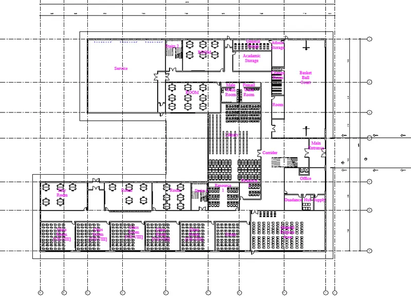
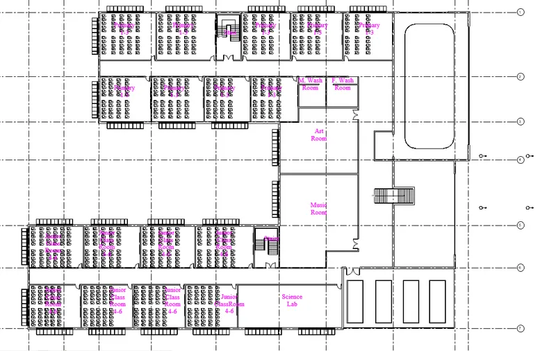
Step 2 Creating the section view
- Go to view tab----------->select section tool from create panel
- Draw the section at the required position
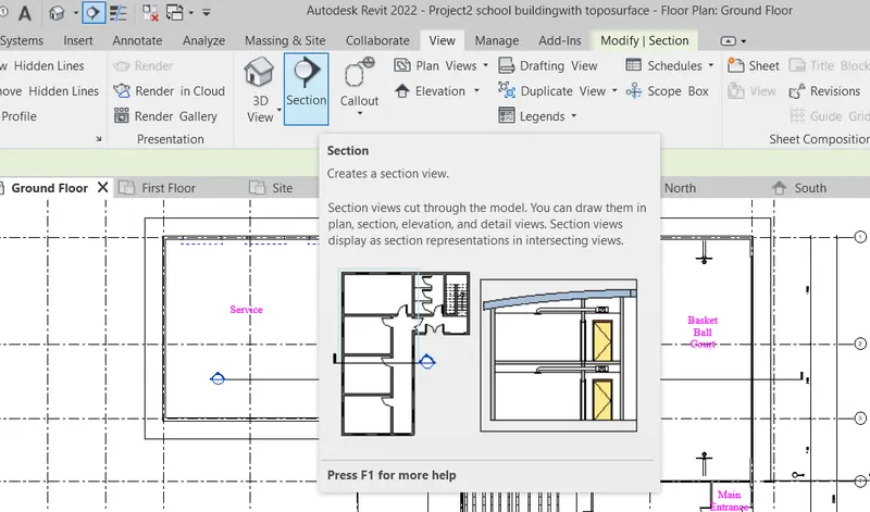
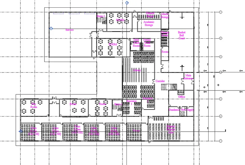
Step 3 creating the floor plan [Architectural]
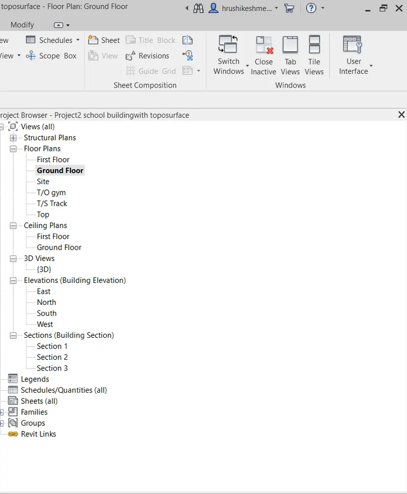
- If the Floor plan is created then it shows at the Project Browser if not show then do the following process.
- Go to view tab------->select plan views tool from create panel----->select floor plan --->select ok.
- Create floor plans for each level.
- Similarly create the structural plans, by selecting the structural plan instead of the floor plan.
Step 4 Sheet Creation
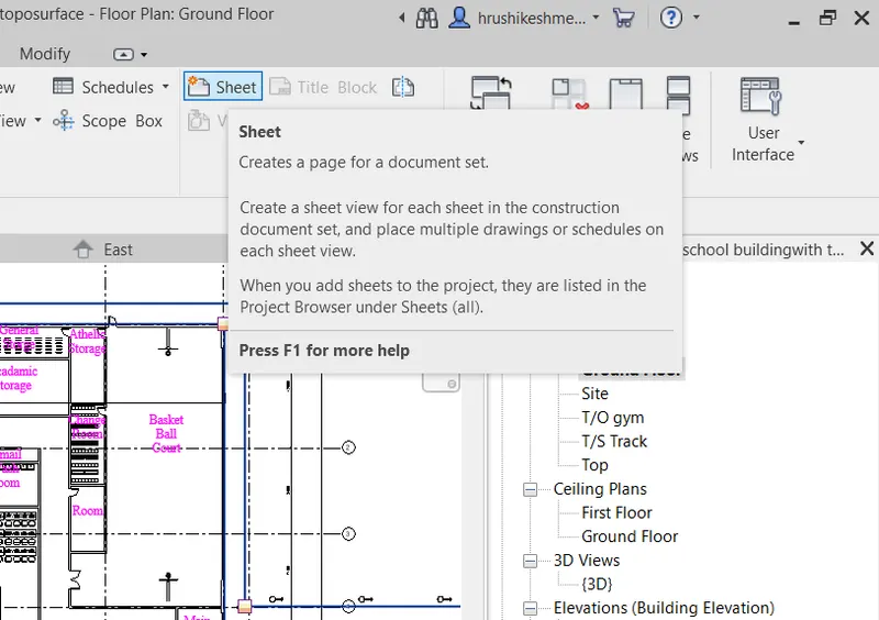
- Go to view tab------>select the sheet tool from sheet composition panel.
- It will open the new sheet dialog box.
- Select the sheet paper size from dialog box.
- It will open the created sheet template as shown below.
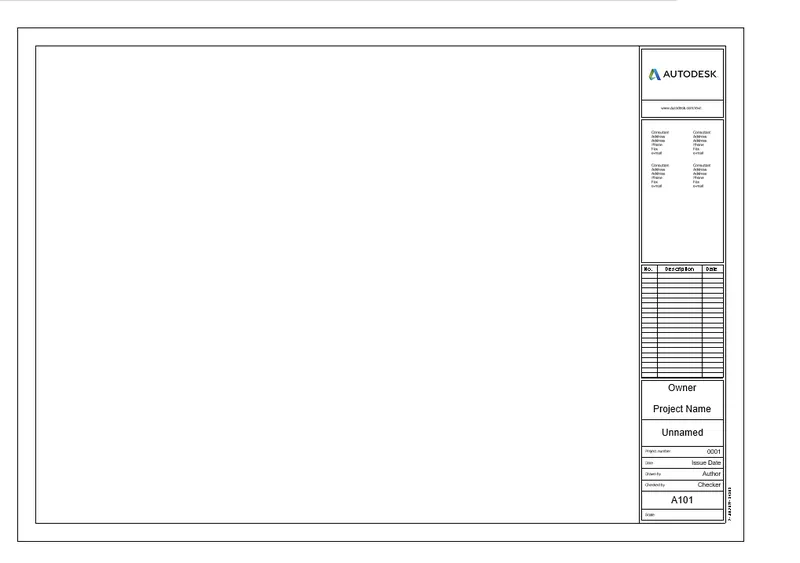
- To adjust the parameters on the sheet double click on the parameter .
- Change all the parameter as per the required value.
Step 5 Sheet Creation Architectural view
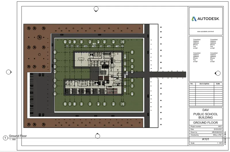
Ground Floor Sheet Creation
- For adding the floor plans in the view, select the ground floor view from project browser and drag the view into sheet as shown below.
- Adjust the scale of view as per requirement using properties window.
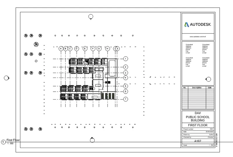
First Floor Sheet Creation
- For adding the floor plans in the view, select the First floor view from project browser and drag the view into sheet as shown below.
- Adjust the scale of view as per requirement using properties window.
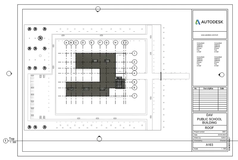
Top/Roof Sheet Creation
- For adding the floor plans in the view, select the Top view from project browser and drag the view into sheet as shown below.
- Adjust the scale of view as per requirement using properties window.
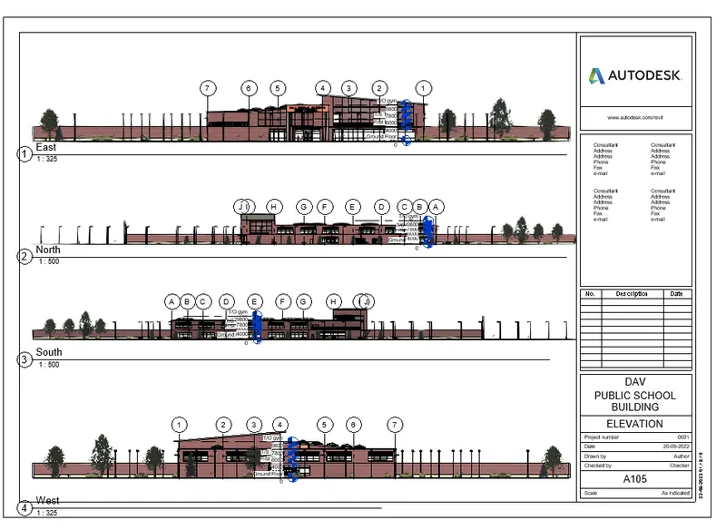
Sheet Creation for Elevation view [EAST,WEST,NORTH,SOUTH Elevation]
- For adding elevation vies in the sheet, select elevation views from project browser and drag the views into the sheet after creating new sheet using sheet tool of view tab.
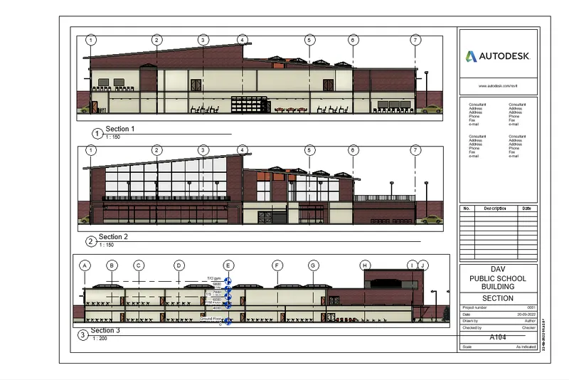
Sheet Creation for created Section view
- Similarly insert the section views into new sheet by dragging the views from the project browser as shown below by adjusting the scale of the view using properties window so that the view fits inside the sheet
Step 6 Sheet Creation structural view
- Open structural template file.
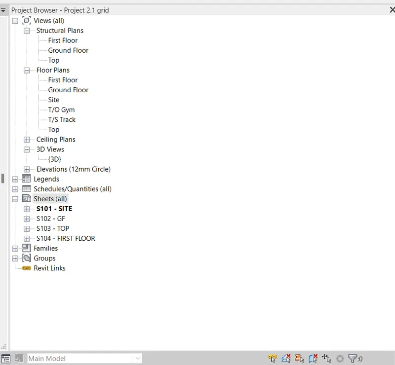
- For creating structural plan
- Go to view tab------>select the plan view tool from create panel----->select the structural plan option
- Select the 1.site view 2.fist floor, 3.Ground Floor,4.Top option and select ok
- Project Browser window the structural plan for Ground Floor,first floor,top is created
Sheet Creation for siteview
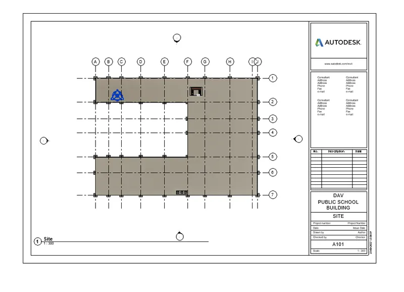
- For adding the floor plans in the view, select the site view from project browser and drag the view into sheet as shown below.
- Adjust the scale of view as per requirement using properties window.
Sheet Creation for Ground floor
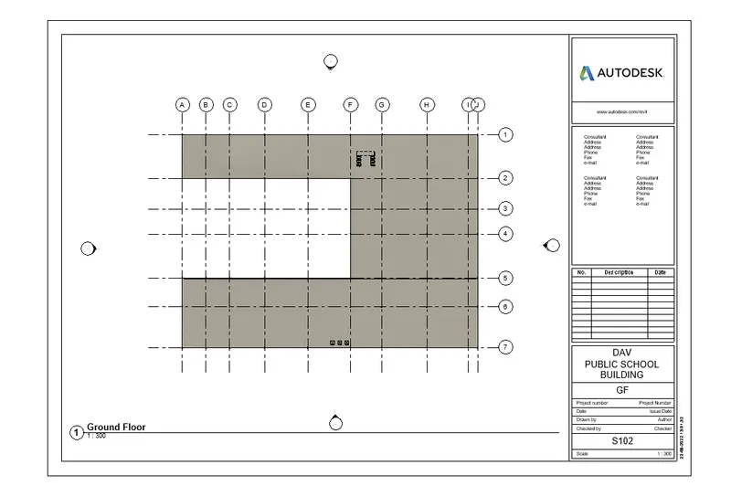
- For adding the Ground floor plans in the view, select the site view from project browser and drag the view into sheet as shown below.
- Adjust the scale of view as per requirement using properties window.
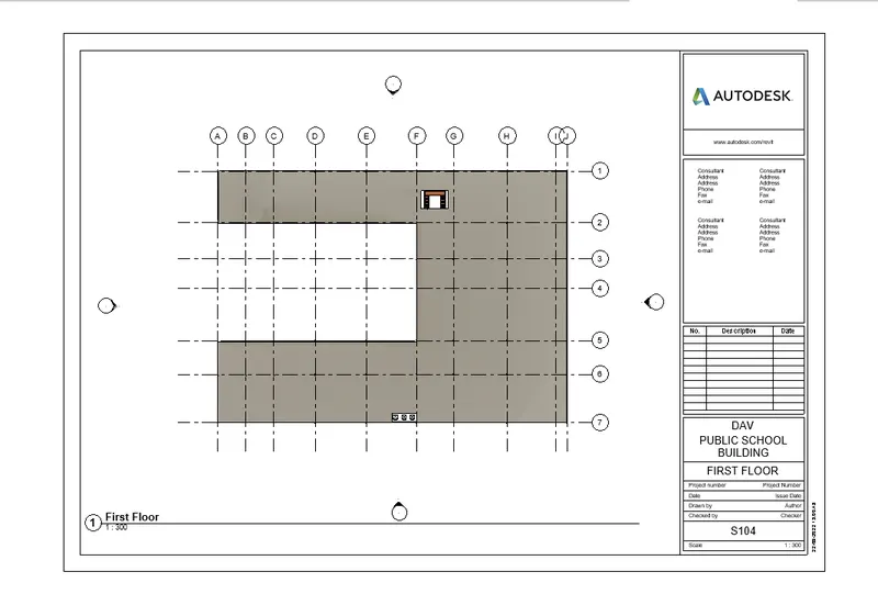
Sheet Creation for First floor
- For adding the First floor plans in the view, select the site view from project browser and drag the view into sheet as shown below.
- Adjust the scale of view as per requirement using properties window.
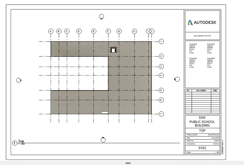
Sheet Creation for Top/Roof
- For adding the First floor plans in the view, select the site view from project browser and drag the view into sheet as shown below.
- Adjust the scale of view as per requirement using properties window.
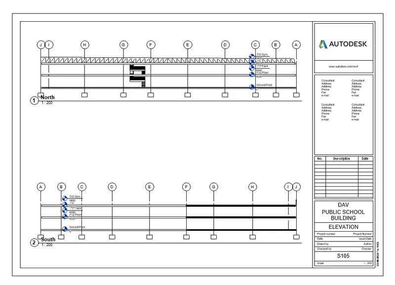
Sheet Creation for Elevation view
- For adding elevation view in the sheet, select elevation views from project browser and drag the views into the sheet after creating new sheet using sheet tool of view tab.
6) Using the Rendering settings, Render images of the 3D model produced and include the rendered images to the drawing sheets
a. Rendering from interior rooms
b. Rendering from out showing topographic features
c. Rendering through structural framing
Aim : To render the images of the 3D model produced and include the rendered images to the drawing sheets by rendering from interior, outside and through structural framing in Revit software.
Procedure :
Step 1
- Open the architectural template file.
Step 2
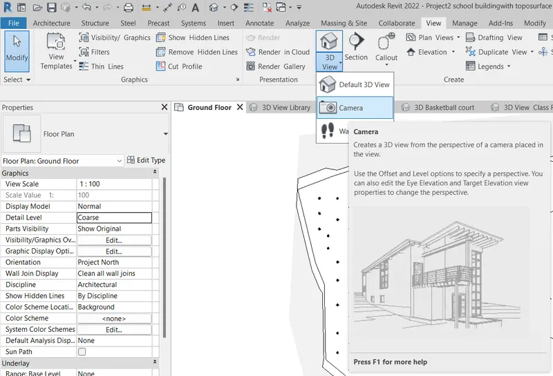
- Go to view tab---->select the 3D view ----->select the camera option & place the camera at the required position to get the 3D camera view.
- The 3D camera view is displayed.
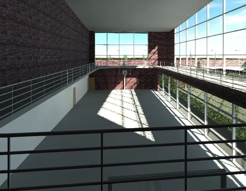
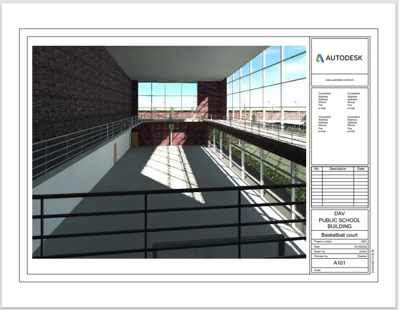
Step 3 rendered view of Basketball court.
- set the camera in the Basketball court using the floor plan view and render the images.
- Go to render tool from presentation panel ------------>it will open the rendering dialog box.
- Select the required resolution as screen or printer------------> scheme as interior sun and artificial----------->click on the render option from rendering dialog box.
- It will start rendering the progress.
- The rendered view of Basket ball ground is shown below.
- Then Export the rendering image.
- Go to the sheet and Insert the renfering file.
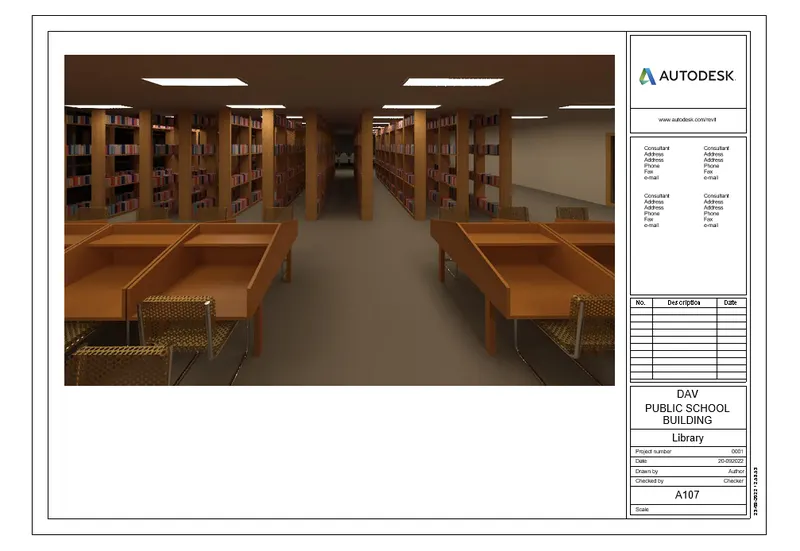
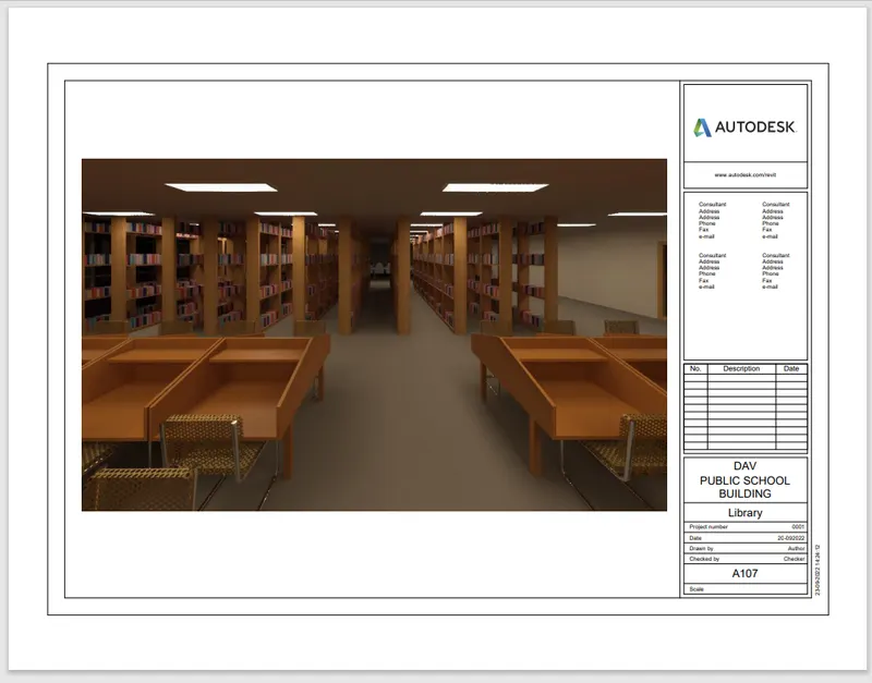
Step 4 Rendered view of Library
- set the camera in the Library using the floor plan view and render the images.
- Go to render tool from presentation panel ------------>it will open the rendering dialog box.
- Select the required resolution as screen or printer, scheme as interior sun and artificial and click on the render option from rendering dialog box.
- It will start rendering the progress.
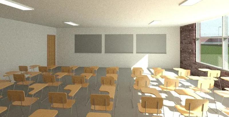
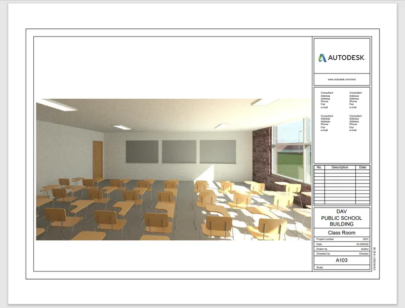
- The rendered view of Class Room is shown below.
- Then Export the rendering image.
- Go to the sheet and Insert the renfering file.
Step 5 Rendered view of classroom
- set the camera in the Class room using the floor plan view and render the images.
- Go to render tool from presentation panel ------------>it will open the rendering dialog box.
- Select the required resolution as screen or printer, scheme as interior sun and artificial and click on the render option from rendering dialog box.
- It will start rendering the progress.
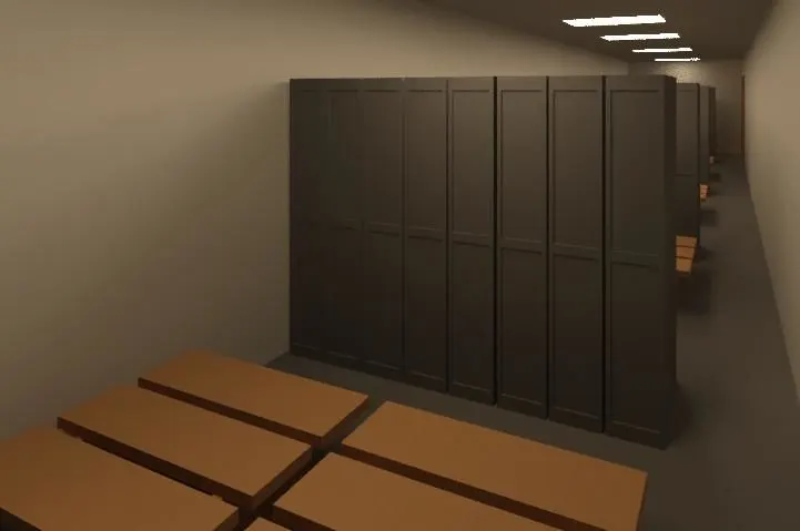
- The rendered view ofGirls changing room is shown below.
- Then Export the rendering image.
- Go to the sheet and Insert the renfering file.
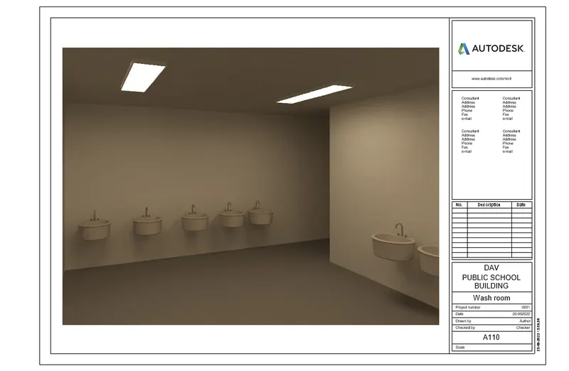
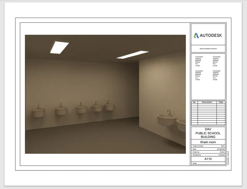
Step 6 Rendered view of Wash room
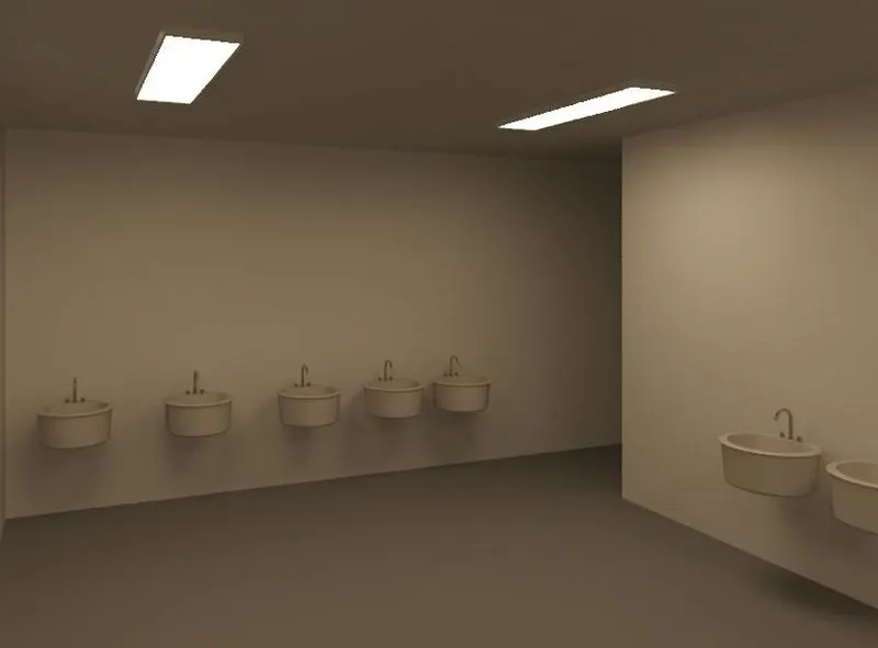
- set the camera in the Wash room using the floor plan view and render the images.
- Go to render tool from presentation panel ------------>it will open the rendering dialog box.
- Select the required resolution as screen or printer, scheme as interior sun and artificial and click on the render option from rendering dialog box.
- It will start rendering the progress.
- The rendered view of Wash room is shown below.
- Then Export the rendering image.
- Go to the sheet and Insert the renfering file.
Step 7 Rendered view of Boys washroom
- set the camera in the Boys Wash room using the floor plan view and render the images.
- Go to render tool from presentation panel ------------>it will open the rendering dialog box.
- Select the required resolution as screen or printer, scheme as interior sun and artificial and click on the render option from rendering dialog box.
- It will start rendering the progress.
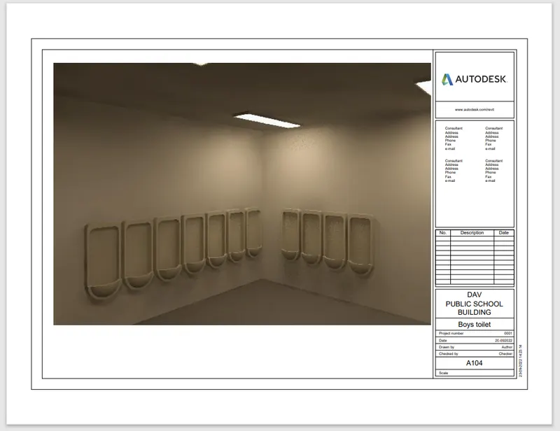
- The rendered view of boys Wash room is shown below.
- Then Export the rendering image.
- Go to the sheet and Insert the renfering file.
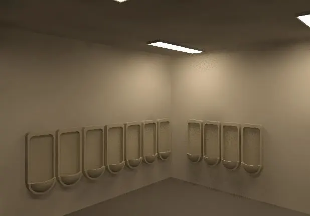
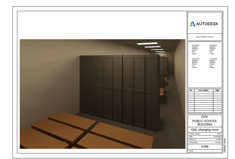
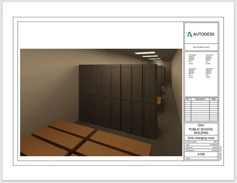
Step 8 Rendered view of Girls changing roomroom
- set the camera in the Girls changing room using the floor plan view and render the images.
- Go to render tool from presentation panel ------------>it will open the rendering dialog box.
- Select the required resolution as screen or printer, scheme as interior sun and artificial and click on the render option from rendering dialog box.
- It will start rendering the progress.
- The rendered view of Girls changing room is shown below.
- Then Export the rendering image.
- Go to the sheet and Insert the renfering file.
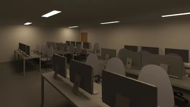
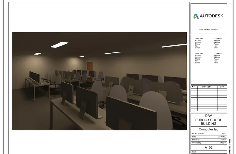
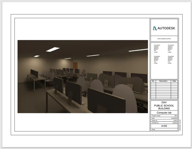
Step 9 Rendered viewComputer lab
- set the camera in the Computer Lab using the floor plan view and render the images.
- Go to render tool from presentation panel ------------>it will open the rendering dialog box.
- Select the required resolution as screen or printer, scheme as interior sun and artificial and click on the render option from rendering dialog box.
- It will start rendering the progress.
- The rendered view of Computer lab is shown below.
- Then Export the rendering image.
- Go to the sheet and Insert the renfering file.
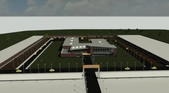
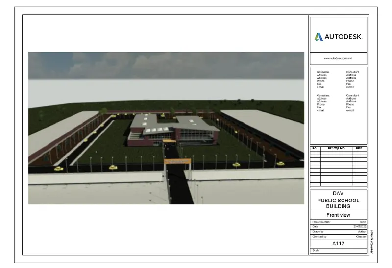
Step 10 Rendered Front view of school
- set the camera at some dist from the plan view and render the images.
- Go to render tool from presentation panel ------------>it will open the rendering dialog box.
- Select the required resolution as screen or printer, scheme as interior sun and artificial and click on the render option from rendering dialog box.
- It will start rendering the progress.
- The rendered view of locker room is shown below.
- Then Export the rendering image.
- Go to the sheet and Insert the renfering file.
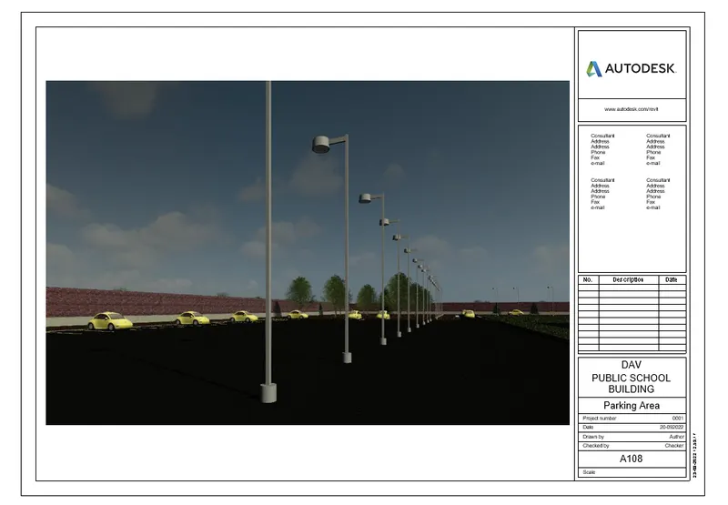
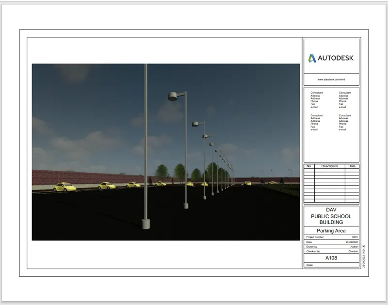
Step 11 Rendered parking area
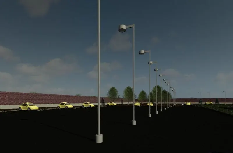
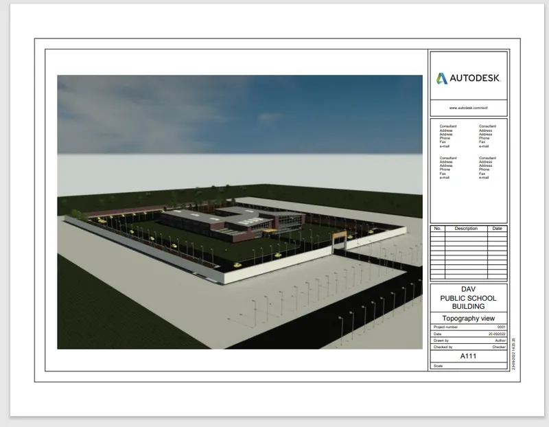
Step 12 Rendered Topographic view
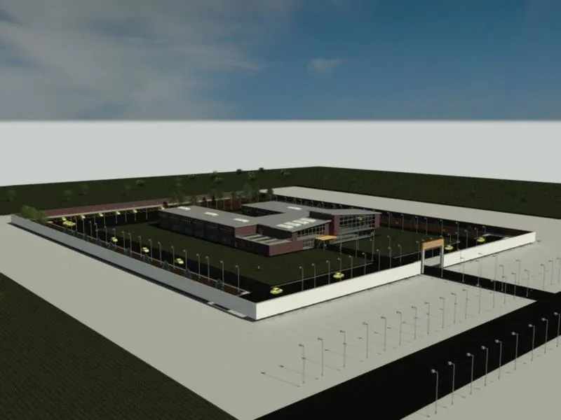
Step 13
- For creating the sheet
- Go to view tab---->select sheet tool from sheet composition panel ---------> select the sheet size from new sheet dialog box ----->select ok.
- Edit the sheet parameters and rename the sheet as per requirement.
- draw all the Sheet of respective views.
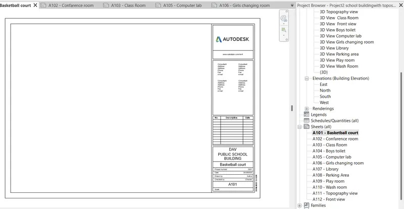
Step 14 Rendering file Insertion
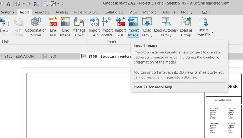
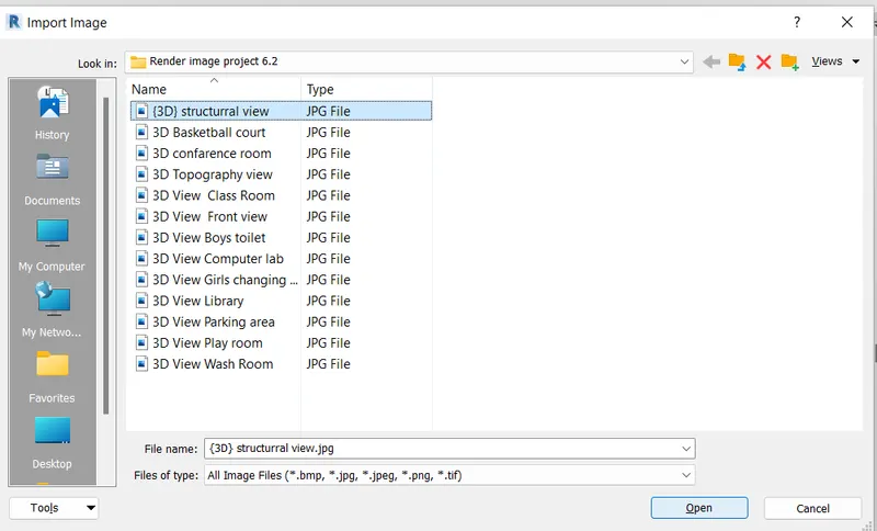
- Select the sheet one by one and import image--> rendering file respectively which we have saved above.
1.Basketball court sheet
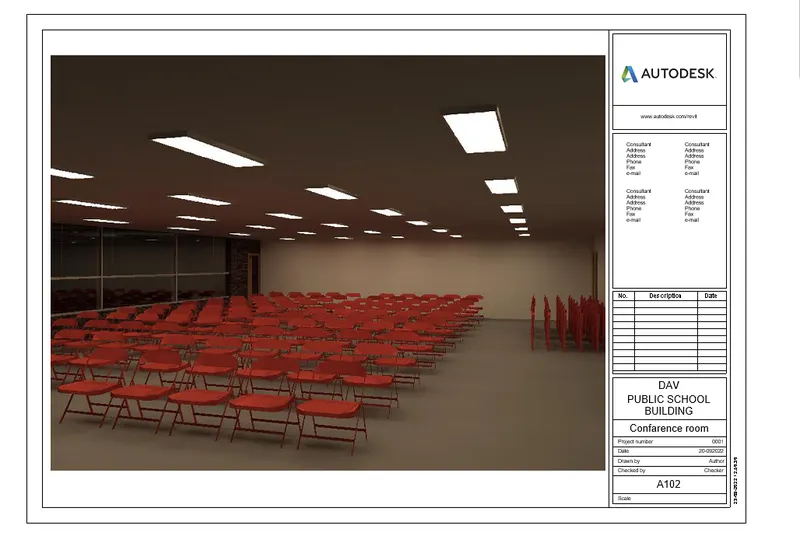
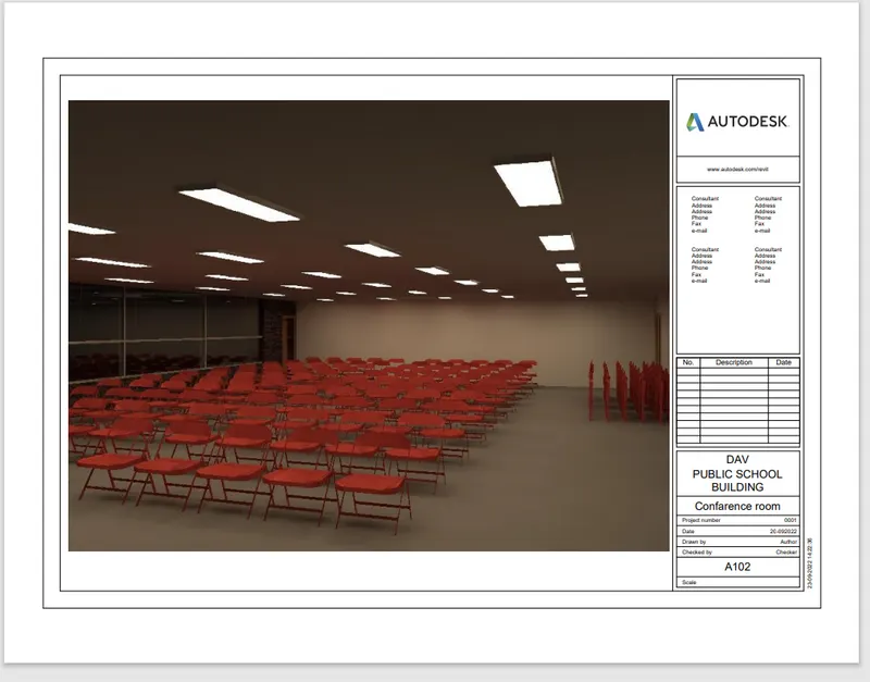
2.Confarence room sheet
3.Class room sheet
4.Boys Toilet sheet
5.Computer Lab sheet
6.Girls changing room sheet
7.Library sheet
8.Parking area sheet
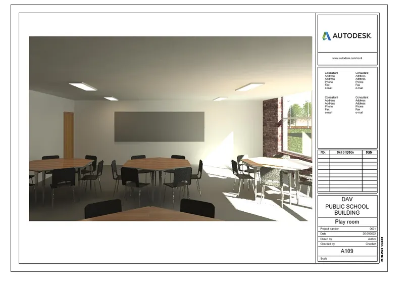
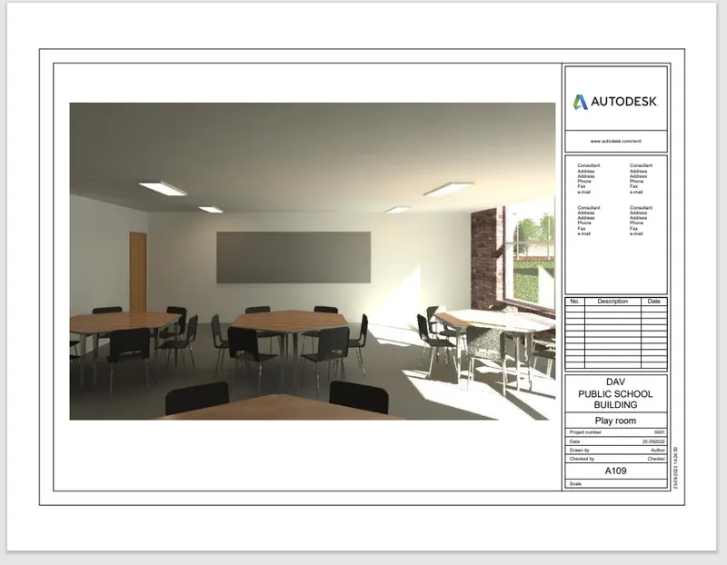
9.Play room sheet
10.Wash room sheet
11.Topography view sheet
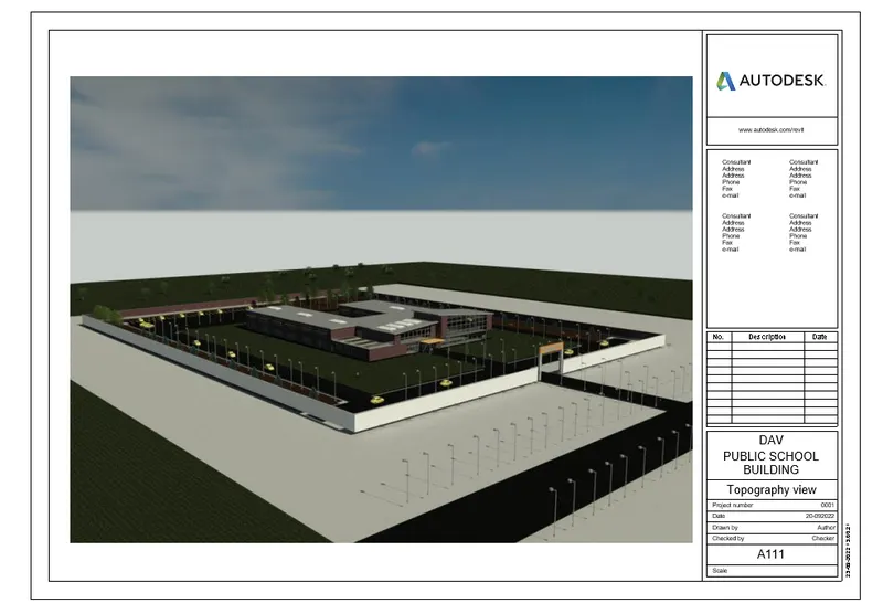
12.Front view sheet
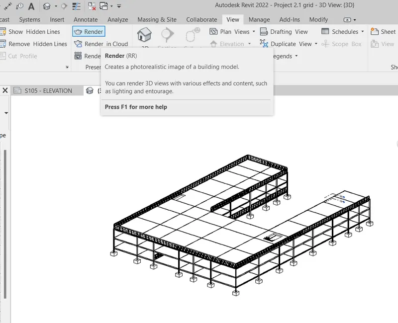
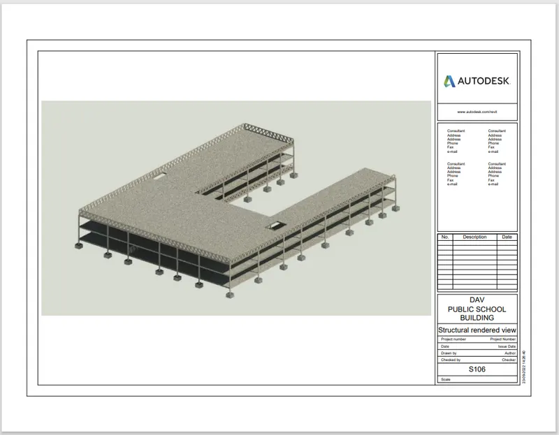
Step 15 Rendering the structural mode
- Open the structural template file .
- Again, Go to view tab, select the rendering tool from create panel and render the view using screen resolution with high quality setting as shown below.
- Export the rendering view for insert in the sheet.
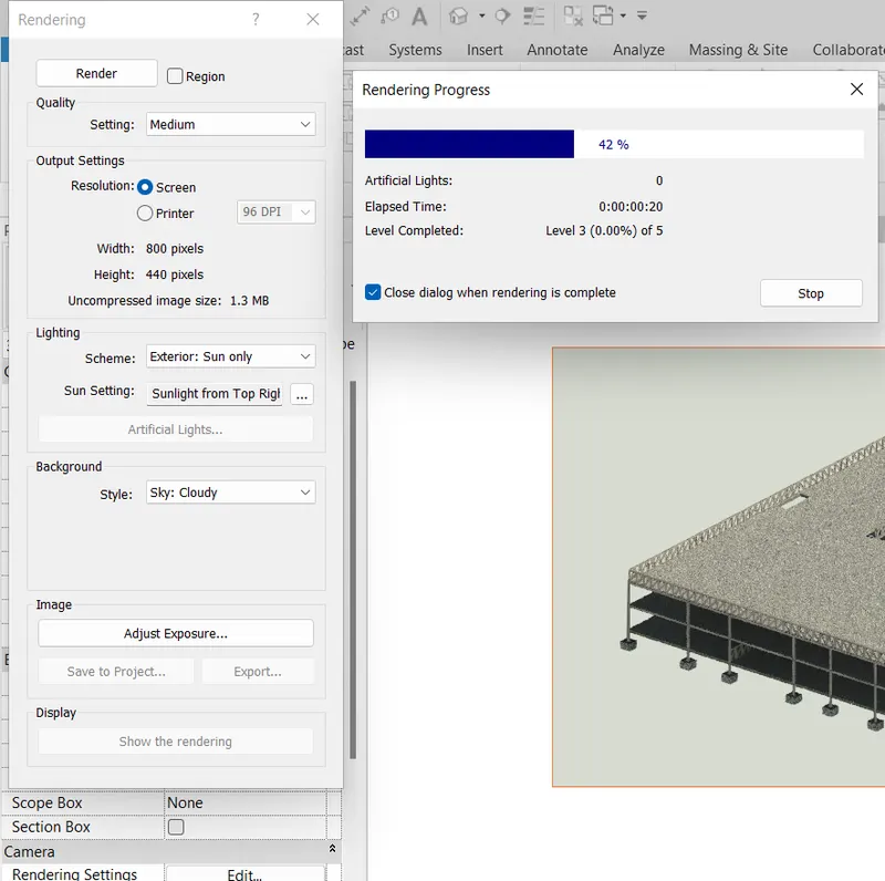
- For creating the sheet for the Structural Drawing.
- Go to view tab---->select sheet tool from sheet composition panel ---------> select the sheet size from new sheet dialog box ----->select ok.
- Edit the sheet parameters and rename the sheet as per requirement.
- Insert the view
- Go to Insert -->Import Image------>Select the strctural rendered image---press ok.
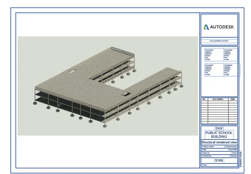
7) Print the set of drawing sheets created and submit the drawings from the architecture and structure model
Aim : To print the set of drawing sheets created and submit the drawings from architecturae and structural model.
Introduction :
- For printing the file we have to convert the file into printable format such as pdf.
- By pressing control and P key we can set the required page layout including the size of the paper etc & convert the file into pdf format.
Procedure :
Step 1
- Open the Revit software
- Click on the architectural template file to open.
Step 2
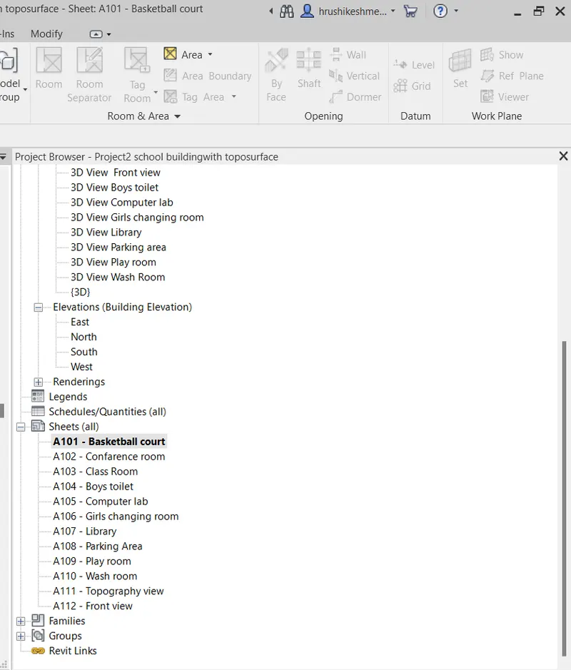
- Open the rendering view from project Browser Sheet folder.
Step 3
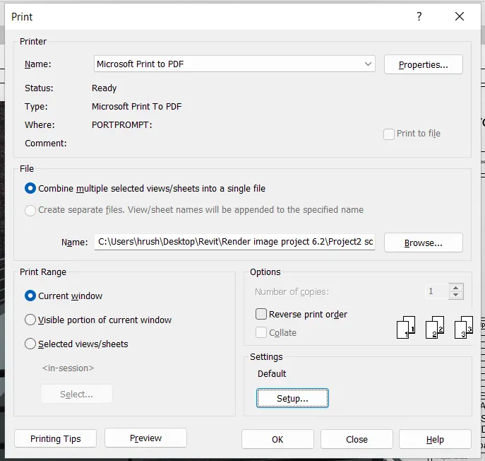
- For printing type control + P key it will open the print dialog box.
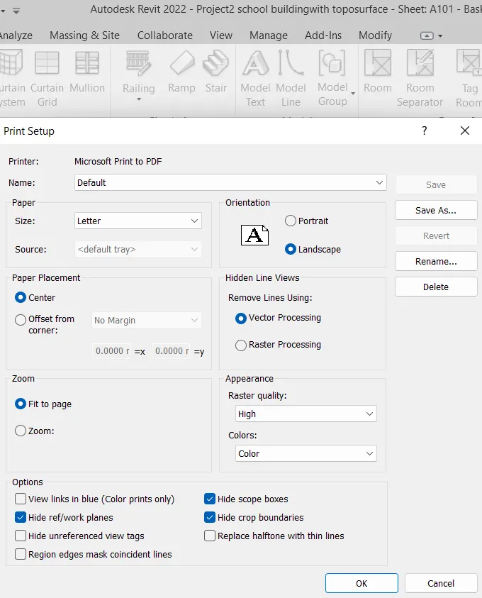
- Select the name as Microsoft print to PDF and choose the page setup option.
- In page setup dialog box, choose the required page setup settings and select ok.
Step 4
- Sheet are created as pdf as shown below.
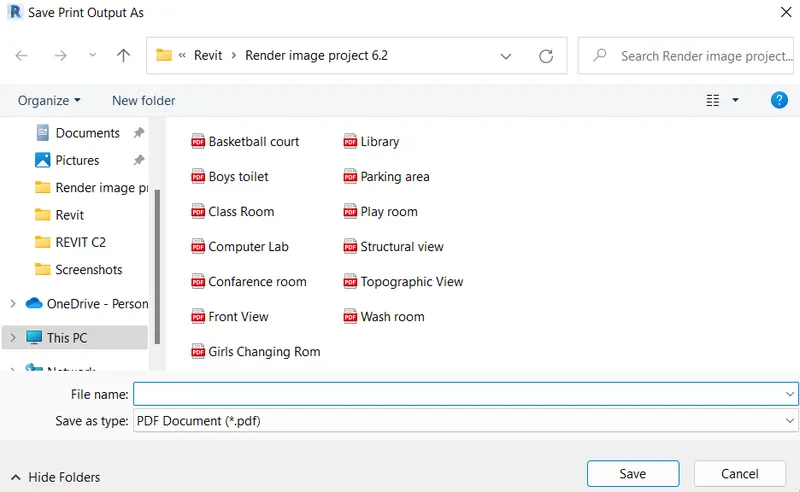
- Rendered Image which I have created nd Make it as pdf Format.
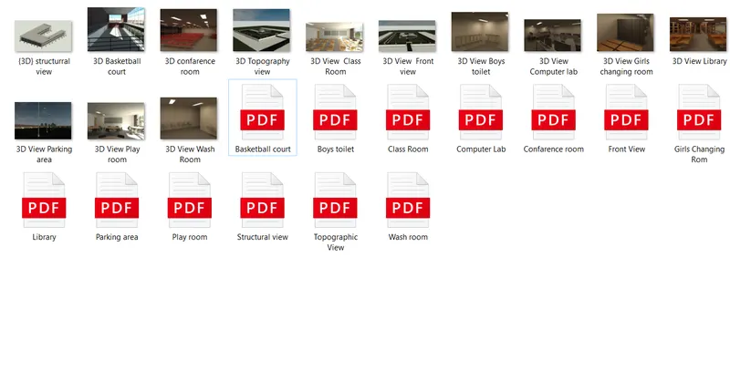
- Rendered Image Pdf view------>
1.Basketball court
2.Boys toilet
3.Class room
4.Computer lab
5.Confarence room
6.Wash room
7.Girls Changing room
8.Library
9.Parking area
10.Play room
11.Structural view of the School Campus
12.Topographic View of the School Campus
13.Front view of the School Campus