Advanced Sheet Metal Design Using NX Cad Challenge_1_Casing Design
TITLE OF PROJECT:
Casing design using NX CAD
OBJECTIVE:
To create a casing using sheet metal tool in Siemens NX.
INTRODUCTION:
NX Sheet Metal provides a set of tools within the NX design environment that allows for simple and fast design of sheet metal parts, dependent on their material and manufacturing process.
Using NX Sheet Metal, parts can be created by using industry best practices and uniform workflows. Standard bending calculations, sheet metal features and advanced analysis tools all contribute to improving quality and reducing the cost of sheet metal parts. In addition, an accurate sheet metal pattern resulting from the design is correctly passed on to manufacturing and suppliers.
DESIGN METHODOLOGY:
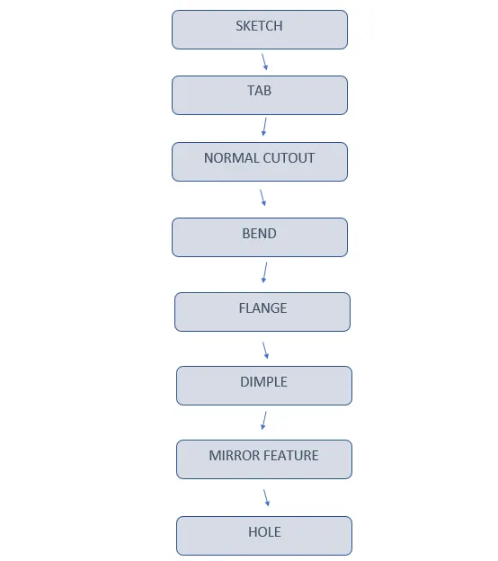
DESCRIPTION:
TAB:
It is used to extrude a sketch as a sheet metal
NORMAL CUTOUT:
It is used to cut the material with provided sketch
BEND:
It is used to bend sheet metal with given sketch line as reference
FLANGE:
Adds a flat flange at an angle planar face and adds bend between them.
BREAK CORNER:
Rounds a sharp corner of a tab or flange.
UNBEND:
Flattens a bend and material adjacent to them.
HOLE:
Adds hole to part with provided sketch.
DIMPLE:
Lift an area of model inside a sketch that simulates stamping tool.
BEAD:
Lift the material along the contour of a sketch that simulates stamping tool.
MIRROR FEATURE:
Copies the feature and mirror it along the plane.
REBEND:
Restores unbend feature to its previous bent state.
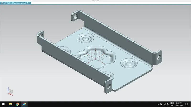
CAD IMAGES OF CASING DONE USING SIEMENS NX:
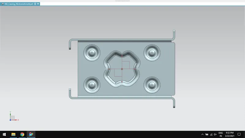
TOP VIEW:
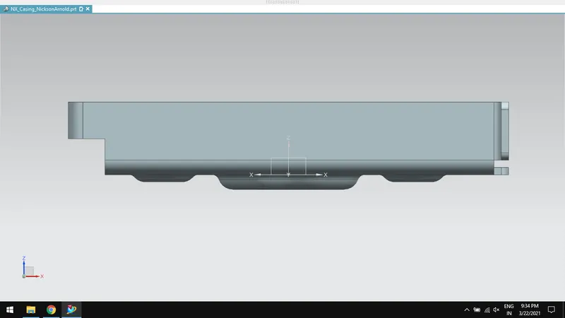
FRONT VIEW:
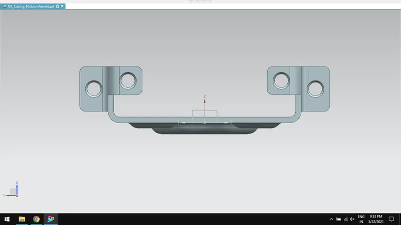
SIDE VIEW:
ISOMETRIC VIEW:
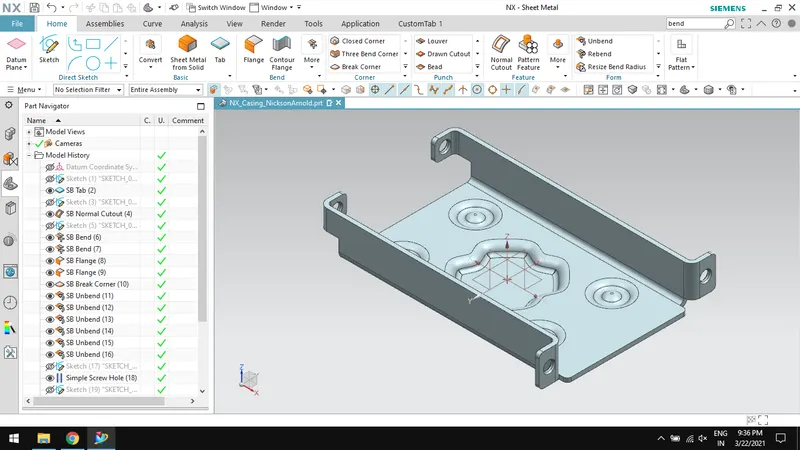
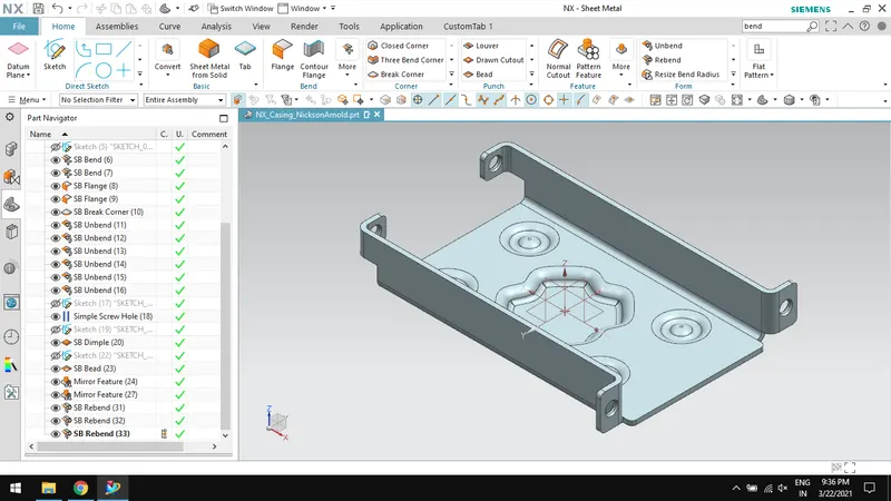
MODEL TREE IMAGES:
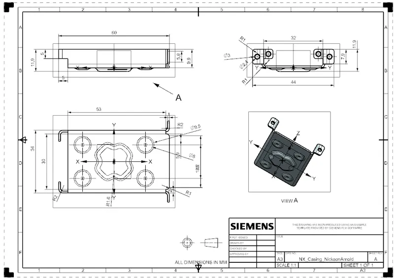
DRAWING SHEET IMAGE:
CONCLUSION:
Thus, creating a casing design is done using sheet metal tools in Siemens NX.