Week 8 - Challenge 5 - Core & Cavity Design
Aim:
Create the Core and cavity blocks for the switch bezel design.
Introduction:
Core:
Core is the side of the tool where the plastic part is injected from. It is the male part which forms the internal shape of molding. It is also the half of the mold where ejectors, side-action cams and other complex components are located.
Cavity:
The cavity is the female part which forms external shape of molding. It forms the major external surfaces.
Parting Line:
Typically, the core and cavity separate as the mold opens, so that the part can be removed. This mold separation occurs along the interface known as the parting line.
Parting Surface:
Generally, injection mold has two major components, the movable half and the fixed half, during injection molding process, these two halves are pressed tightly and form a sealed hollow to avoid the melt flow leakage and maintain certain holding pressure, the pressed surface are called parting surface.
Methodology:
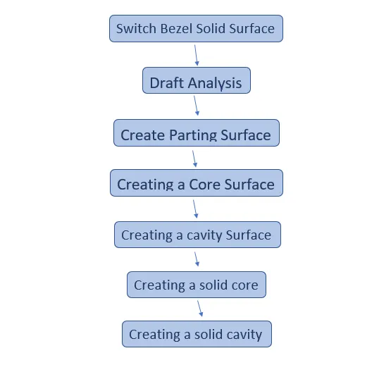
Switch Bezel
Take switch bezel surfaces as the input for designing parting surface.
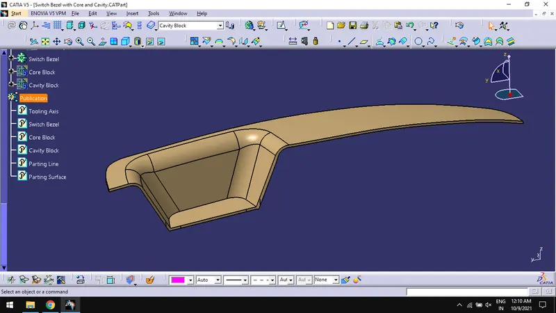
Creating a Parting Surface
- Create a boundary for the class A surface and extrapolate the surface to an extent.
- Trim the extrapolated surface with class C surface.
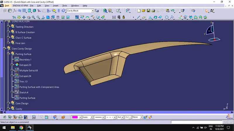
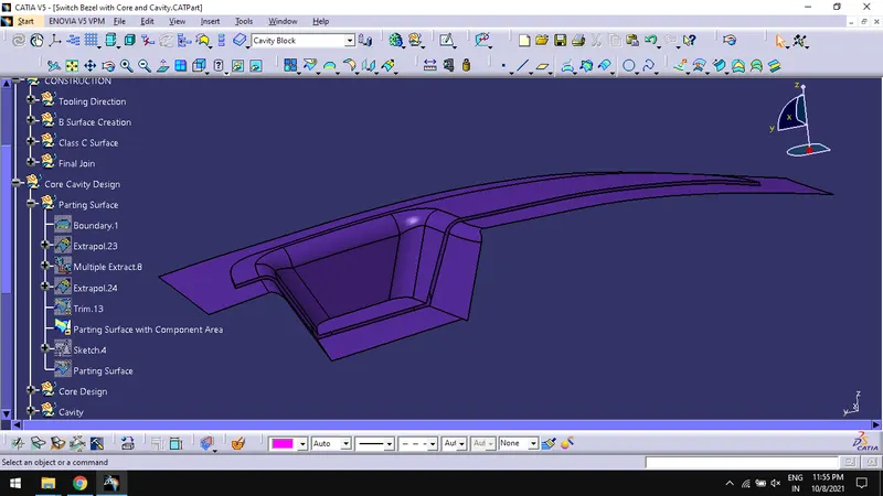
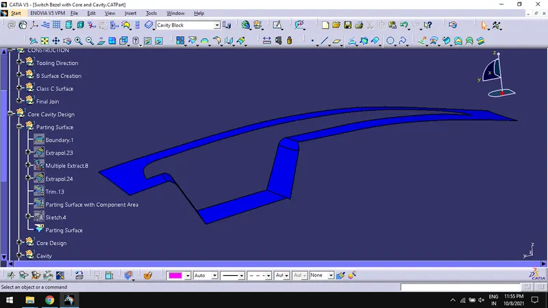
- Trim the above resultant surface with class B surface to get PARTING SURFACE WITH COMPONENT AREA.
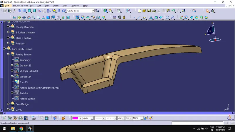
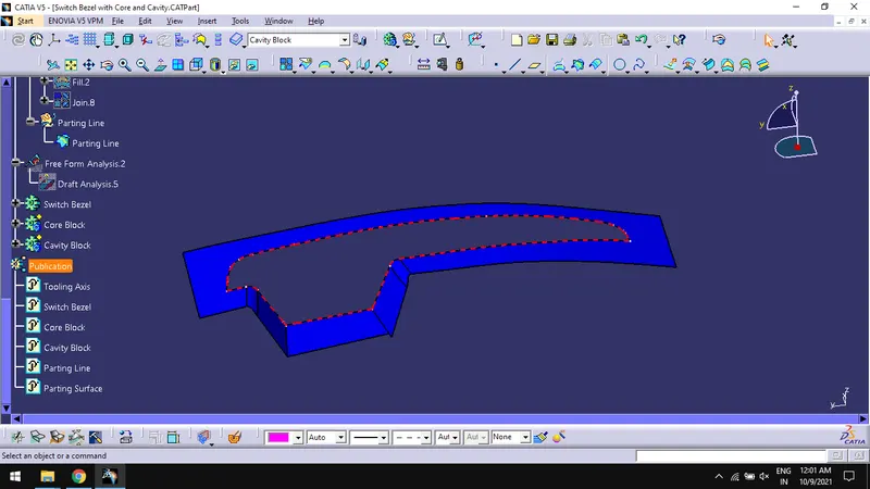
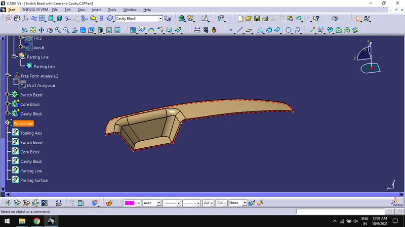
- Create PARTING LINE by intersecting class B surface with class C surface.
Creating Core Surface:
- Create a sketch in XY plane of the axis system created earlier and draw a rectangle using construction element.
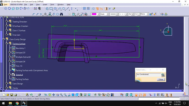
- Constrain them so that the rectangular boundary doesn’t goes beyond the parting surface area.
- Extrude the sketch with tooling axis direction.
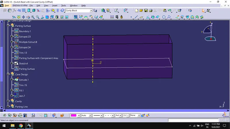
- Trim the extrude with parting surface with component area and fill the top of the trimmed surface with fill command and edges of extrude as boundary.
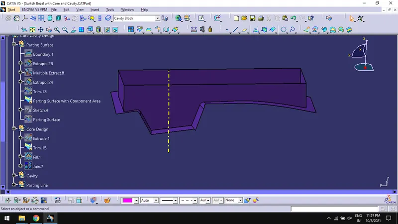
- And join the resultant surfaces using join command.
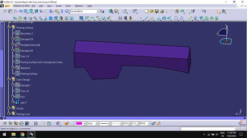
Create a Solid Core:
- Use close surface in part design workbench to create solid core block.
- Translate the body to certain distance in tooling axis direction for better view.
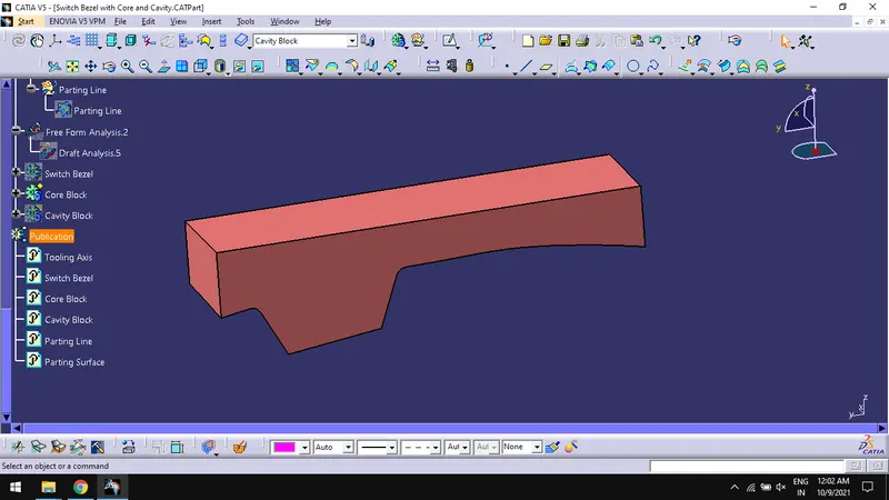
Creating Cavity Surface:
- In surface design workbench, Extrude the rectangular the sketch again with tooling axis direction.
- Trim the extrude with class B surface and fill the bottom of the trimmed surface with fill command and edges of extrude as boundary.
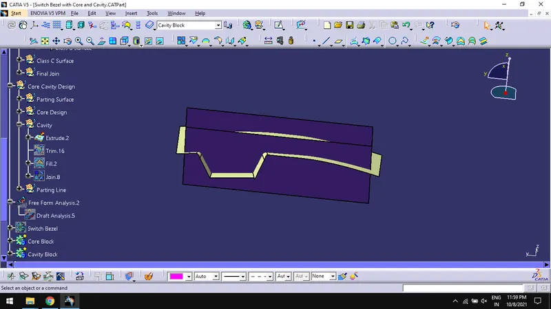
- And join the resultant surfaces using join command.
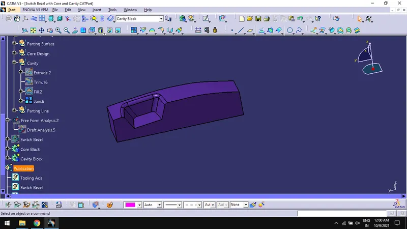
Create a Solid Cavity:
- Use close surface in part design workbench to create solid cavity block.
- Translate the body to certain distance in tooling axis direction for better view.
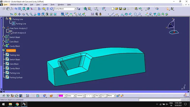
Draft Analysis of the component:
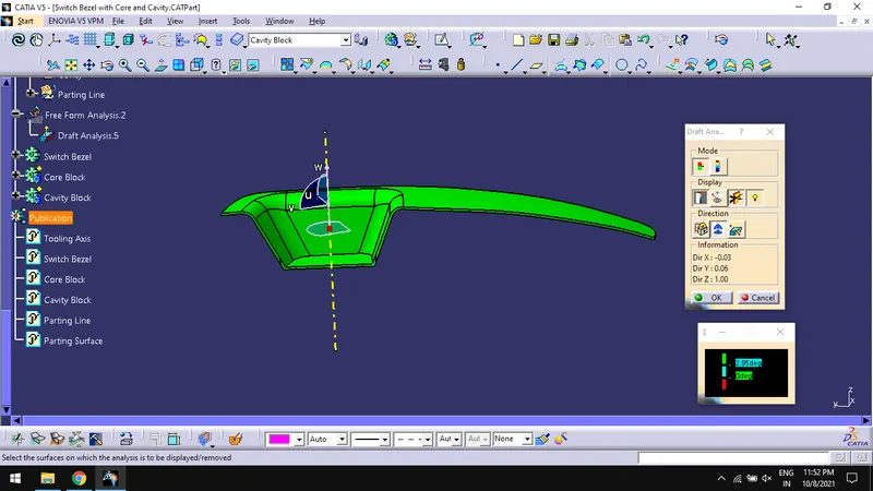
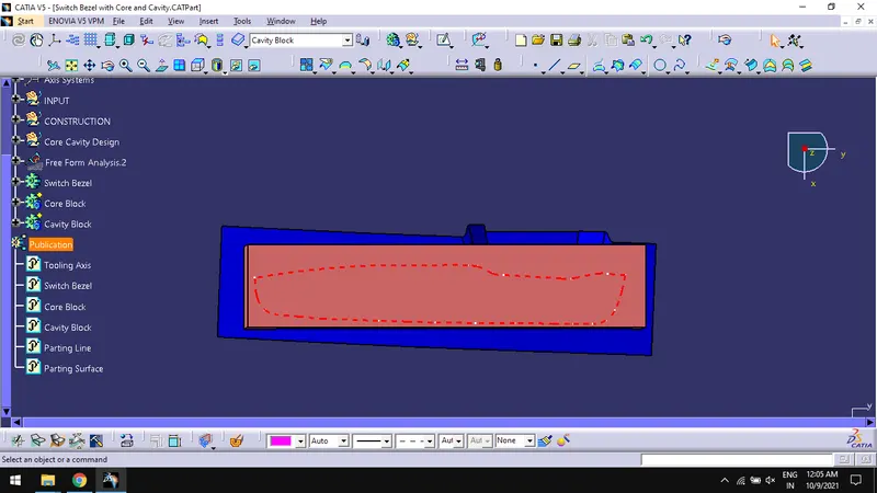
Tree Structure:
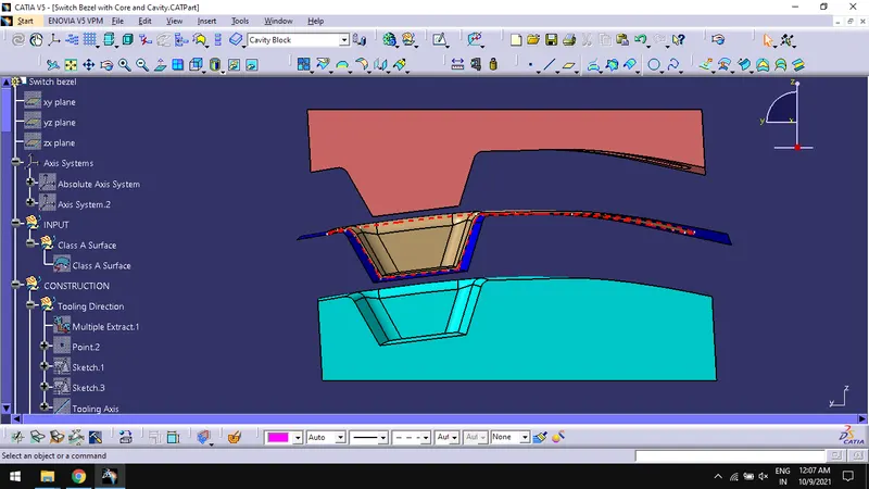
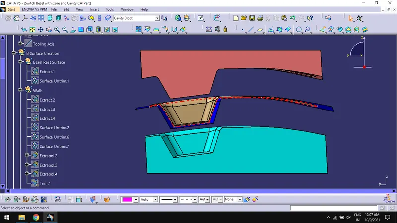
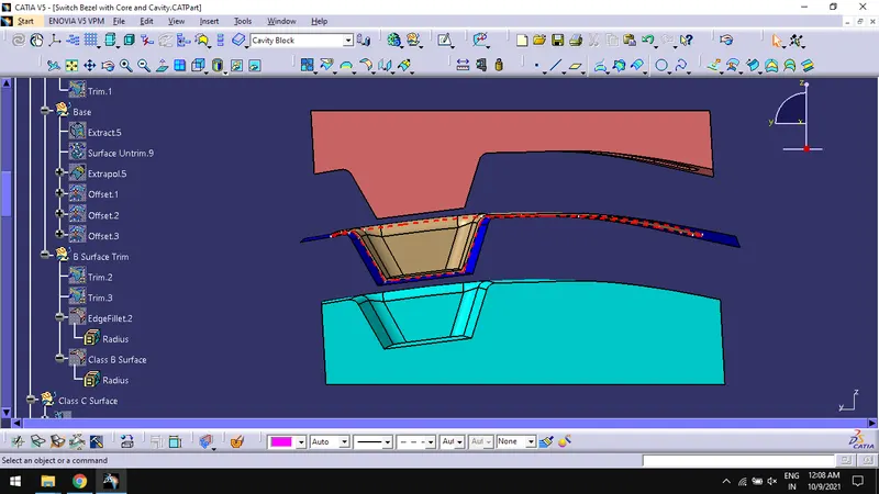
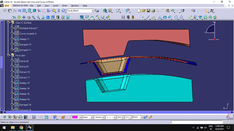
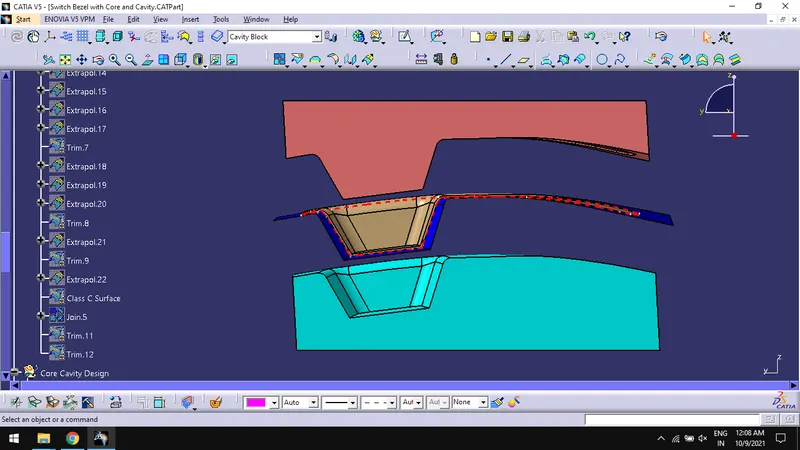
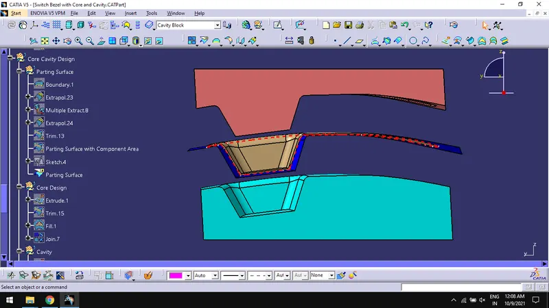
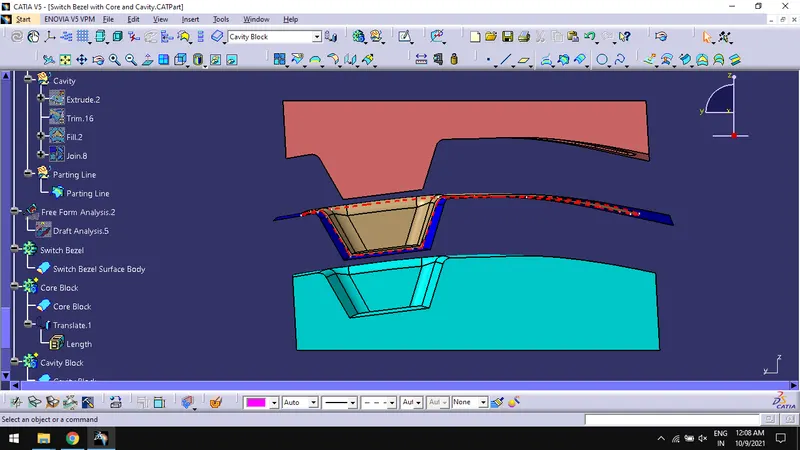
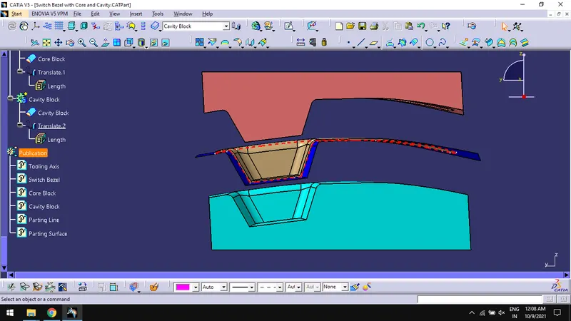
Different Views of the Component:
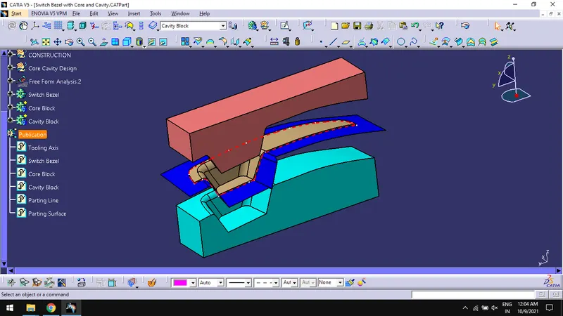
Isometric view:
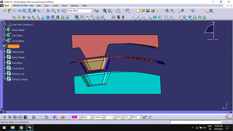
Front view:
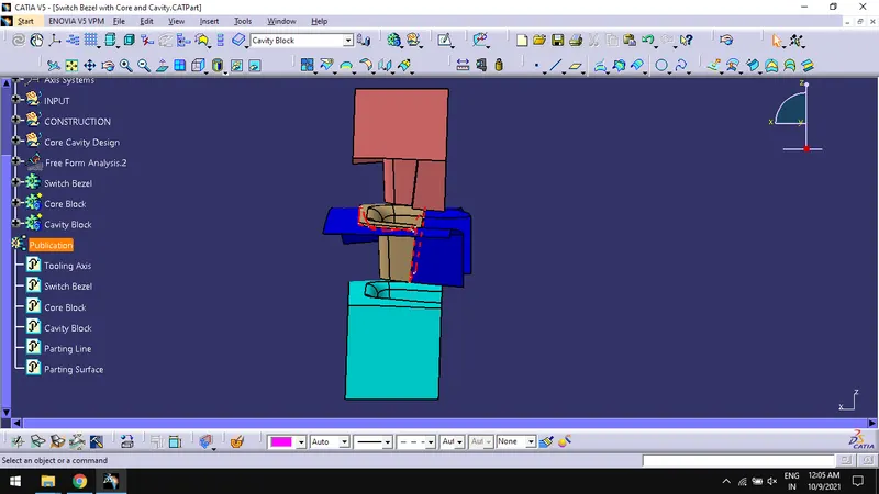
Side view:
Top view:
Conclusion:
Thus, creating the Core and cavity blocks for the switch bezel design are done successfully.