Week 8 - Challenge 4 - Coin Holder Design
AIM:
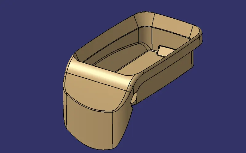
To create the Coin Holder Plastic component through the given Class-A surface with tooling axis should be created meeting the requirements of the draft angle and perform the Draft analysis on the model.
Class A Surface:
Tooling Axis:
Tooling axis is a direction which defines manufacturability of the part. It is basically the direction that the mold pulls apart.
Draft Analysis:
The Draft Analysis command enables you to detect if the part you drafted will be easily removed. This type of analysis is performed based on color ranges identifying zones on the analyzed element where the deviation from the draft direction at any point, corresponds to specified values. Most applications require minimum draft angle of around 0.5o to 1o, however 3o draft angles are widely accepted
To find Draft analysis option, Go to Insert > Analysis > Feature Draft Analysis.
Methodology:
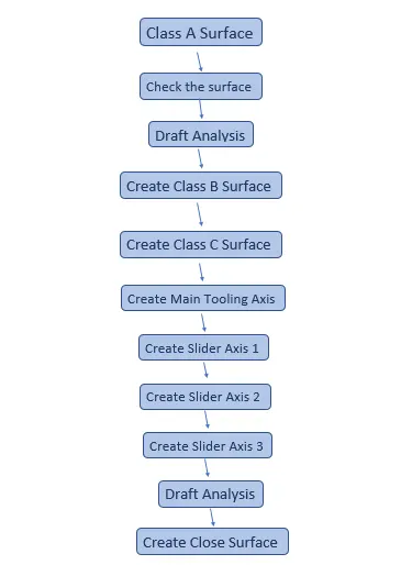
Check the Surface
Check the connectivity of the given class A surface with options such as join, Boundary and dis-assemble surface.
Join:
Check the connectivity using join command by selecting the surface as joining elements.
Boundary:
Using Boundary command, check for connectivity of the surface by selecting surface edges
Dis-assemble:
Dis-assemble the element by choosing ‘domain only’ as an option. After checking the connectivity of the given we can delete the curves we got as dis-assemble results and join surface from the geometrical sets.
Create Tooling Axis
As we know tooling axis is the direction that mold pulls apart, the tooling axis should be in a way that component completely clears from the mold and also have a very lesser cost of producing it.
- Create a new geometrical set, name it as TOOLING DIRECTION or AXIS.
- Create an extract of the base surface using extract command.
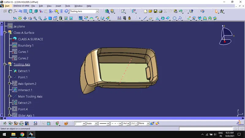
- Make a point by using on surface as option.
- Create an axis line with that point and rename it as MAIN TOOLING AXIS.
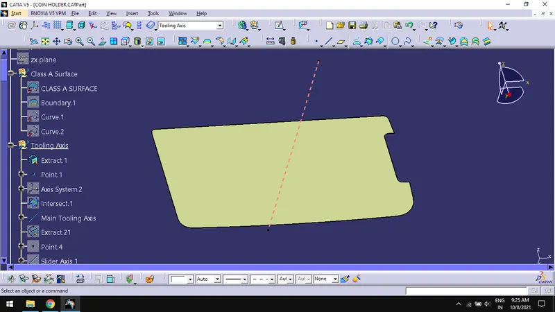
- Use Publication from Tools> Publications for tooling axis and class A surface for creating a reference to their geometrical entities.
DRAFT ANALYSIS
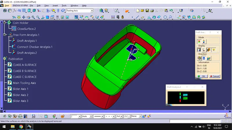
- Change the view to ‘material mode’ in customize view option.
- To find Draft analysis option, Go to Insert > Analysis > Feature Draft Analysis.
- Select the mode of operation as quick analysis.
- Selection display option using color scale window.
- Use the compass for selecting the tooling axis in draft direction option and select the surface and lock them.
- If the color scale matches the color of the surface, then the component drafted can be easily removed.
Create Class B Surface
- Extract and extrapolate the surfaces one by one and trim them into a relevant surface
And offset the trim to the required thickness.
- Trim the offsets to create the final surface which is 2.5mm offset from Class A surface in downward direction.
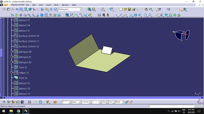
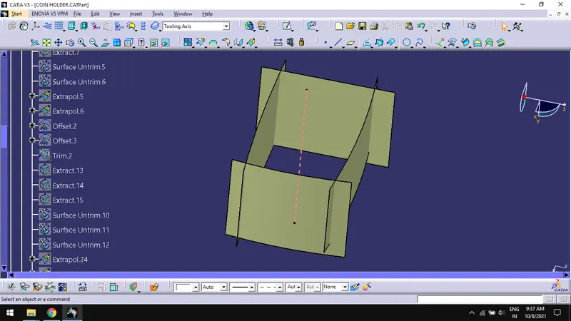
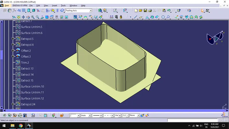
- Create this B surface involves, creating 4 separate portions namely BASE, SIDE WALL, TOP WALL, OUTER FLANGE and trimming them together.
BASE
SIDE WALL
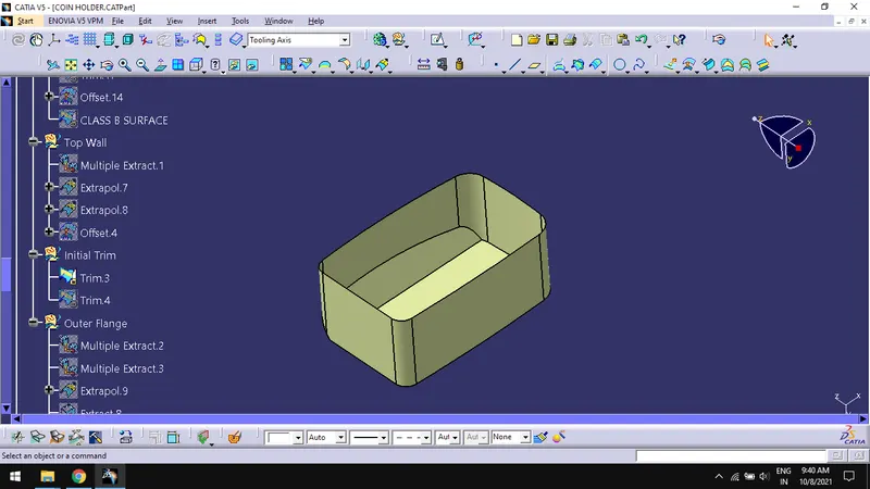
TOP WALL
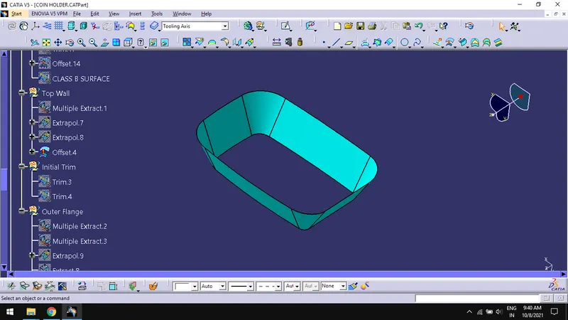
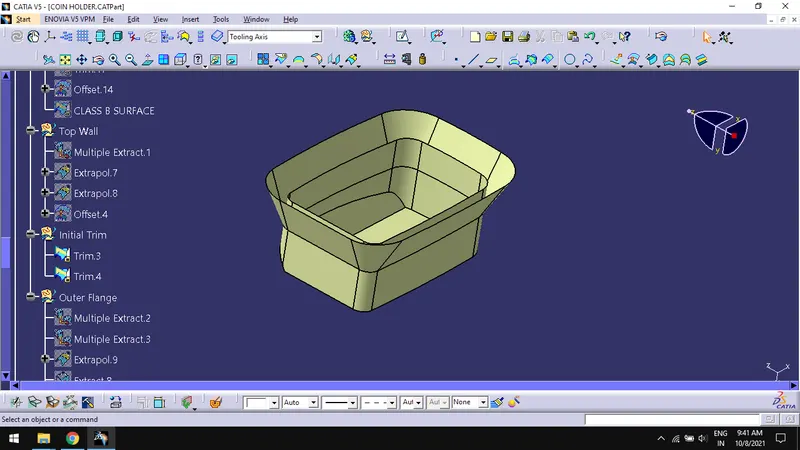
OUTER FLANGE
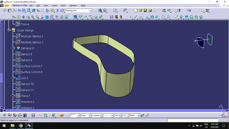
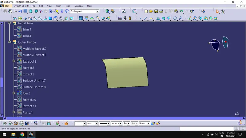
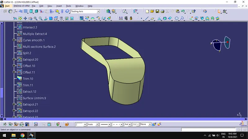
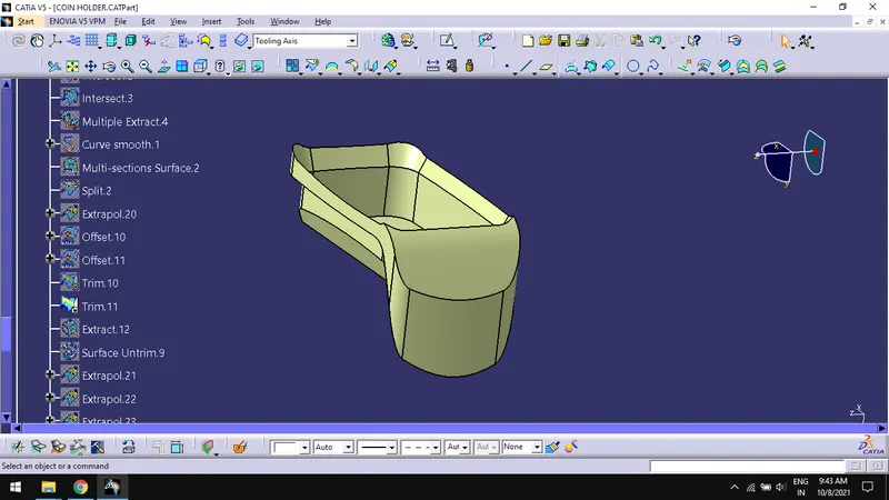
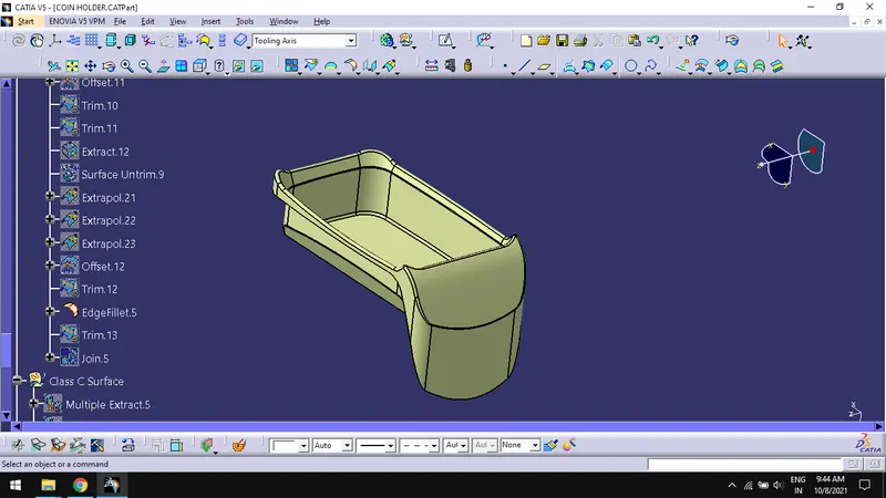
- The above surface after trimming is class B surface, rename the surface as “Class B Surface” and publish them for easy access.
Create Class C Surface
- Class C surface is the join surface of class A and Class B surfaces.
- Extract the edges of class A surface which relevant to create C surface using multiple extract command.
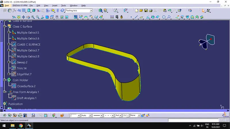
- Extract the surface of class A for creating C surface using multiple extract command.
- Use Sweep ‘line’ with ‘with reference surface’ and guide curve as extracted edges created earlier and extracted surfaces as reference surface in 900 angles in inward direction.
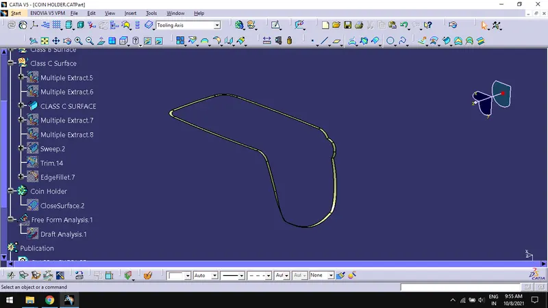
- Repeat the above process for creating C surface for circular cutout.
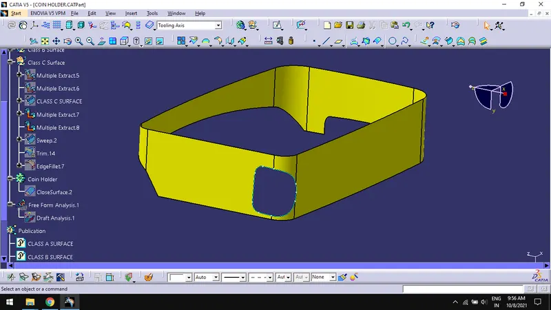
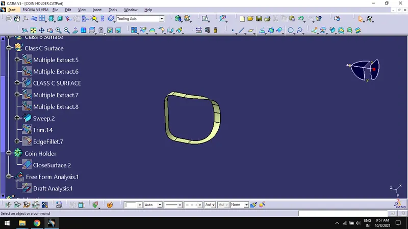
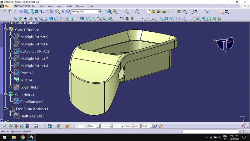
- Trim the class B surface with class C surface.
- Publish them for easy access.
Create Close surface
In part design workbench, create a close surface with the finally trimmed surface.
Draft Analysis of the solid:
- Do draft analysis for the solid part using MAIN TOOLING AXIS, change the orientation to cover most of the part.
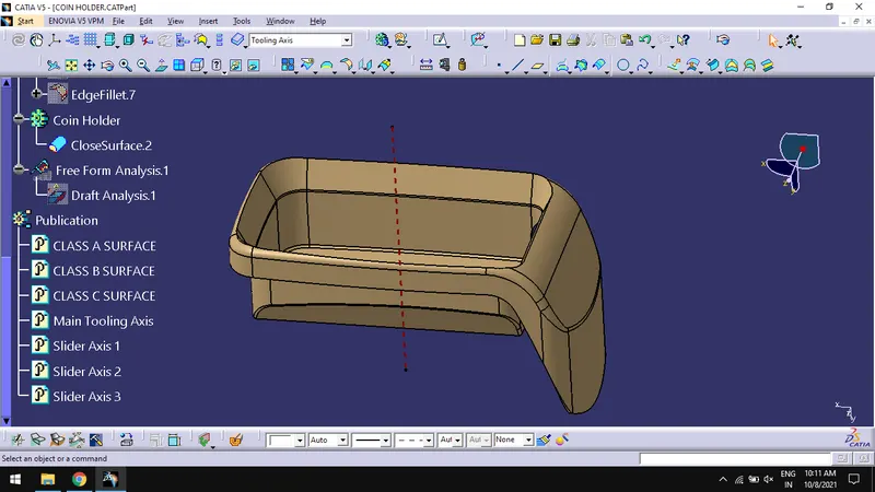
- Lock the orientation and create a line using a point and compass direction. Rename the line as SLIDER AXIS 1 and reset the compass in view menu.
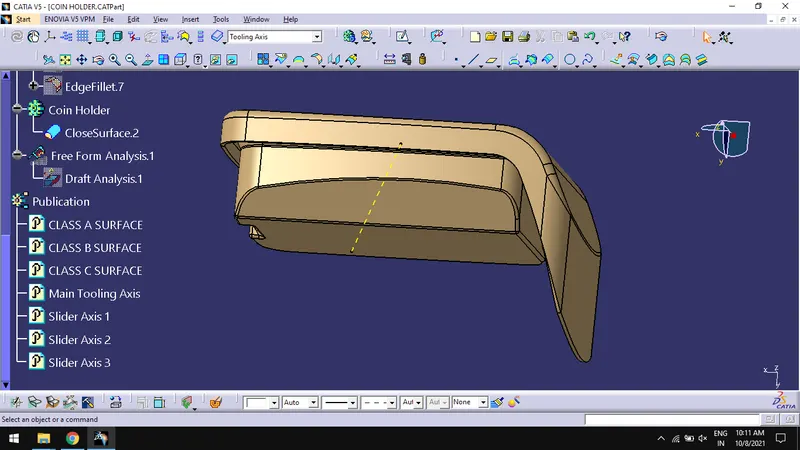
- Again, do the draft analysis using the main tooling axis, change the orientation to cover the remaining surface which are left in MAIN TOOLING AXIS and SLIDER AXIS 1.
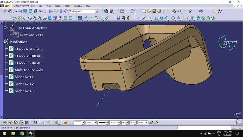
- By locking the orientation, create a line using the point and compass direction. Rename the line as SLIDER AXIS 2 and repeat the process to get SLIDER AXIS 3.
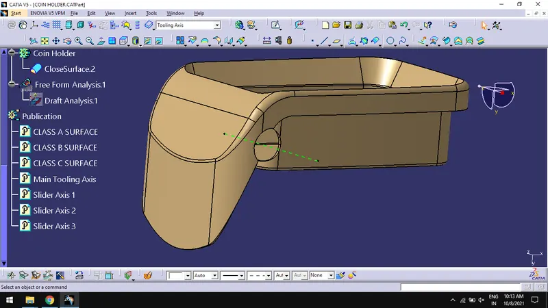
Draft Analysis with Main Tooling Axis:
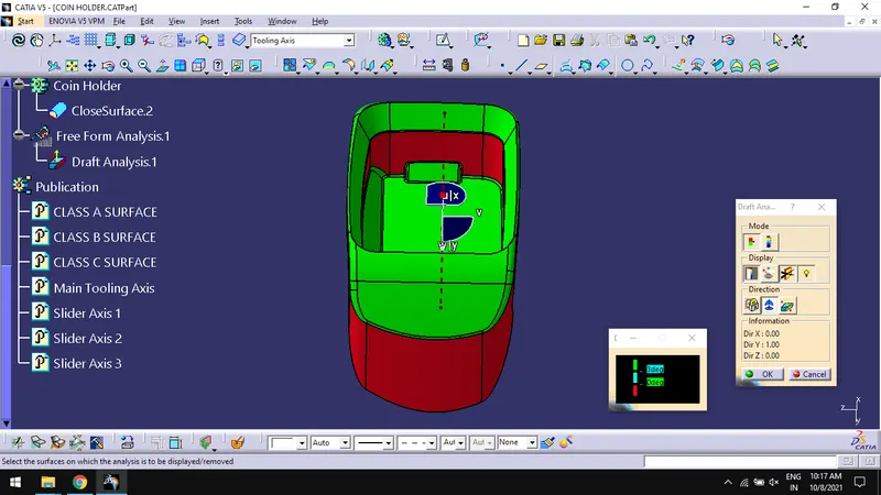
Draft Analysis with Slider Axis 1:
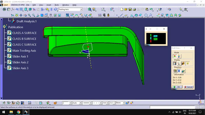
Draft Analysis with Slider Axis 2:
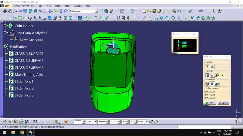
Draft Analysis with Slider Axis 3:
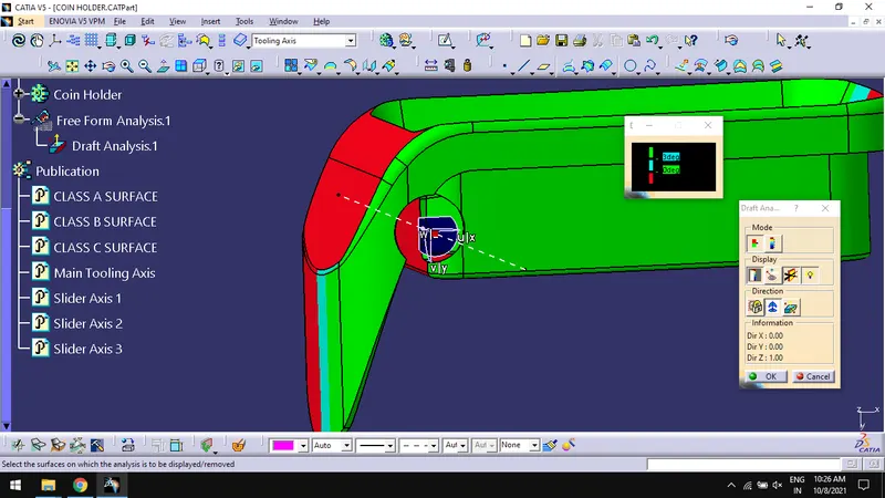
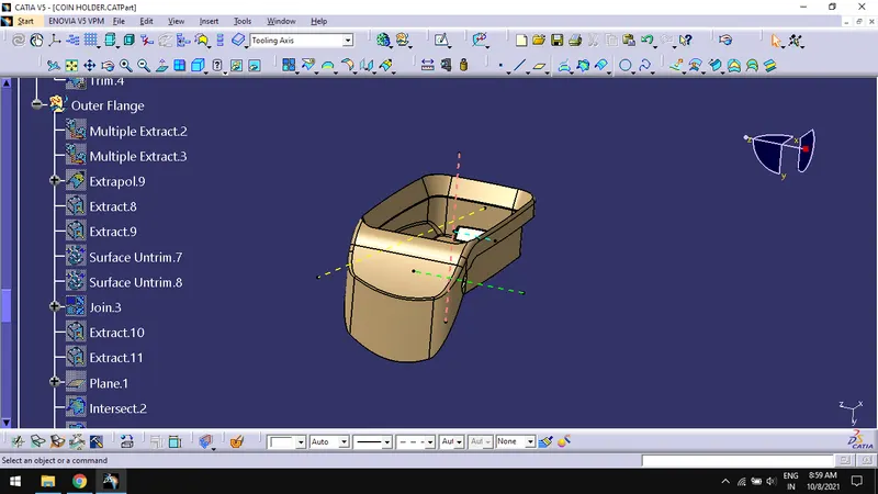
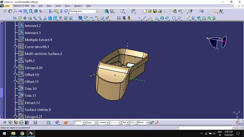
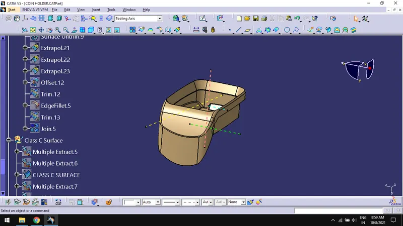
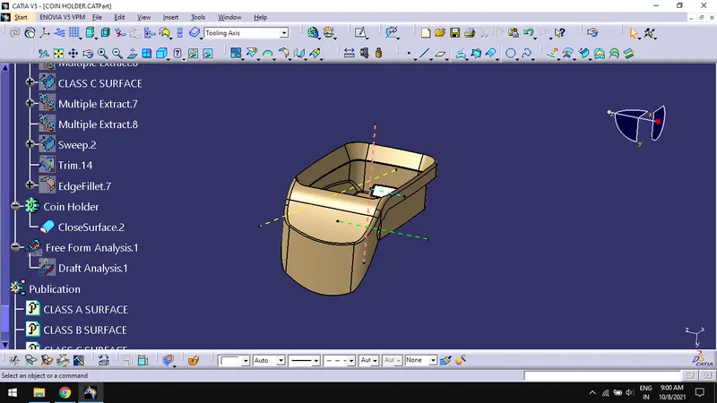
Tree Structure:
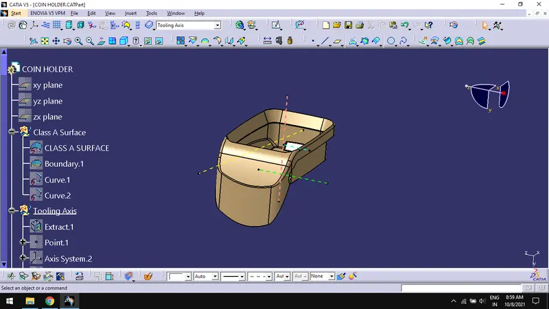
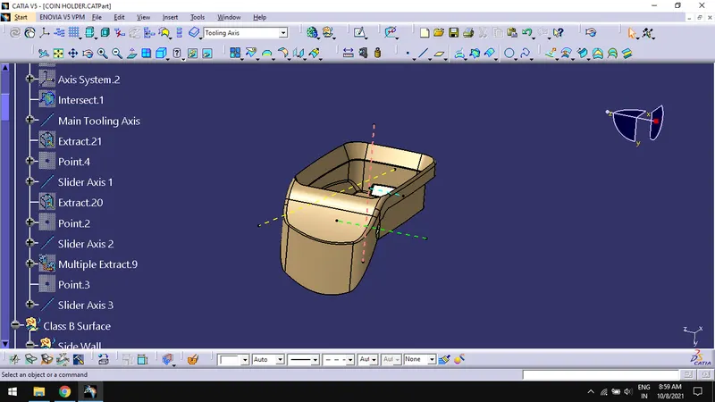
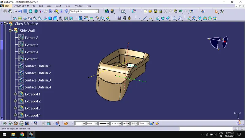
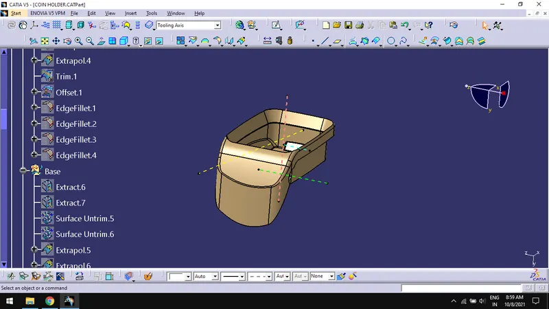
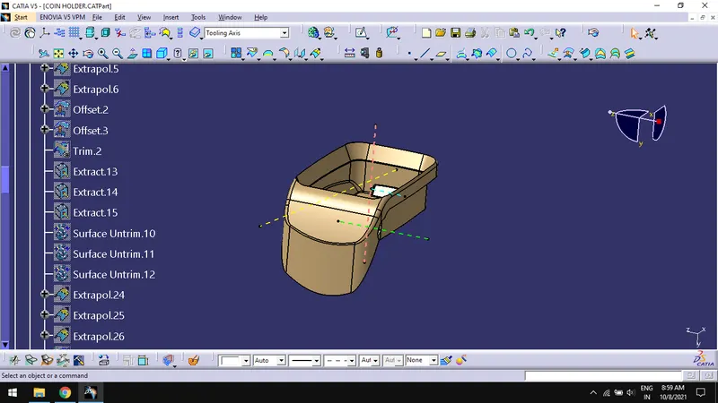
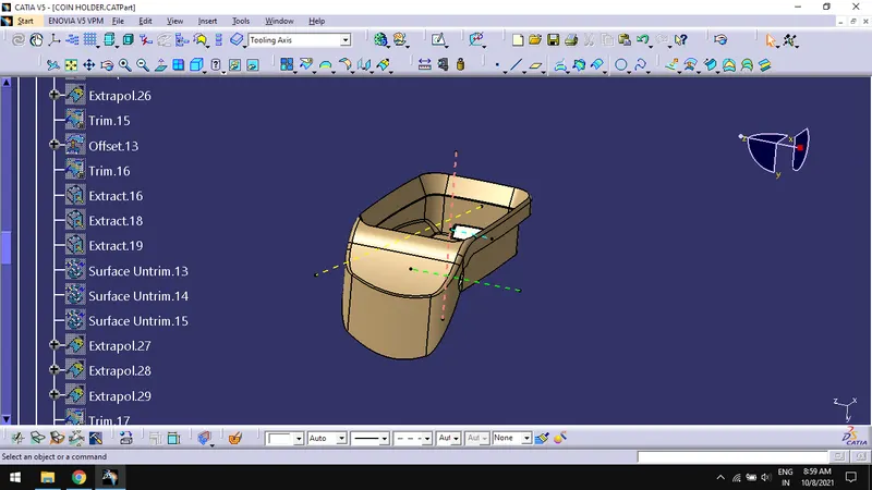
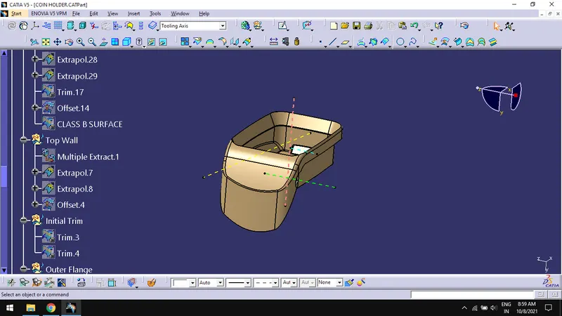
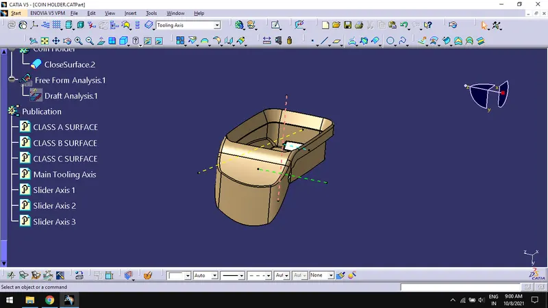
Different views of the solid coin holder:
Isometric view:
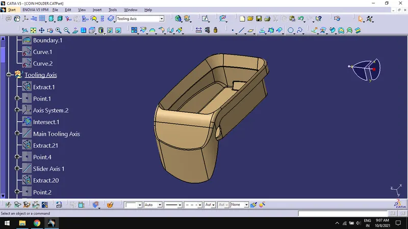
Front view:
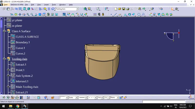
Side view:
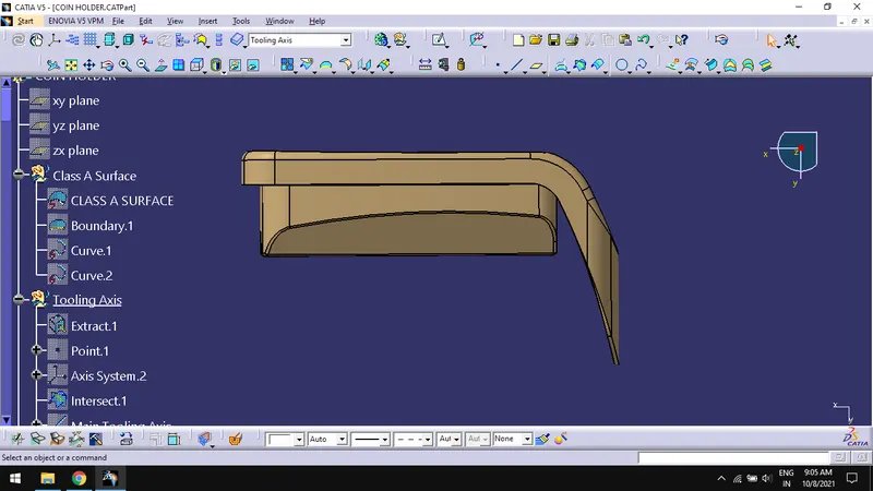
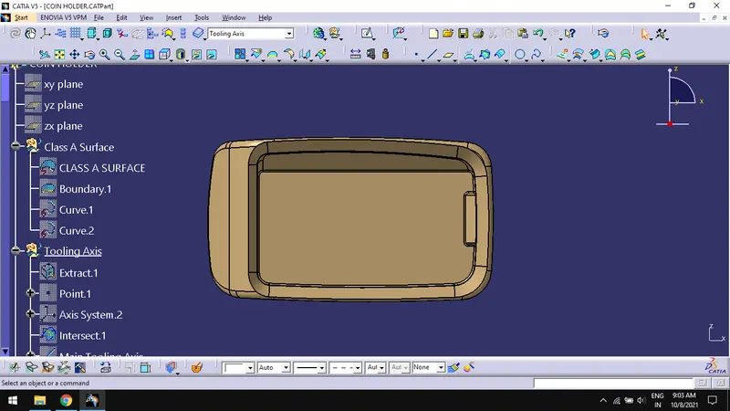
Top view:
Conclusion
Thus, creating the Coin Holder Plastic component through the given Class-A surface with the tooling axis should be created meeting the requirements of the draft angle and perform the Draft analysis on the model are done successfully.