Week 9 - Project 1 - Door Applique Design with Engineering Features
AIM:
Create the Door Applique Plastic component through the given Class-A surface along with Heat Stakes and the locators considering the design rules for the door applique and at the end perform the Draft analysis on the model.
Methodology:
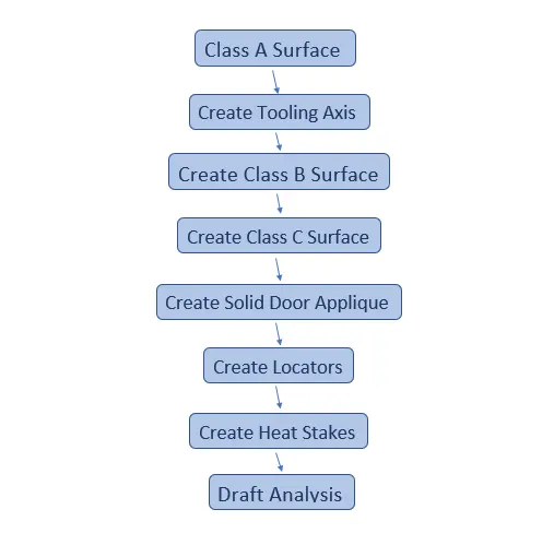
Create Tooling Axis:
- Create a point on the class A surface using point on surface option.
- Create line with point and direction in Y direction.
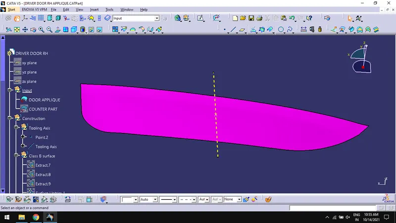
- Rename the line as tooling axis.
Create Class B Surface:
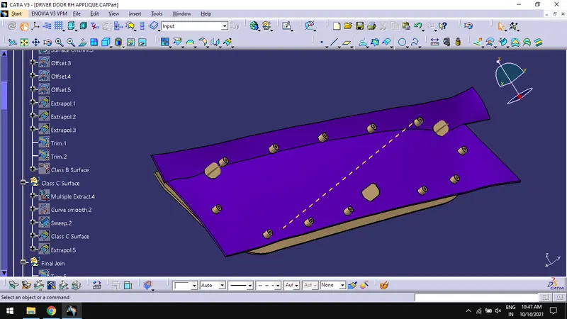
- Create a geometrical set, name it as Class B surface and extract all the surfaces of class A separately using extract command.
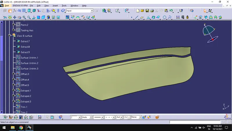
- Untrim all extracted surfaces and offset it for 2.5mm.
- Extrapolate the offset surfaces and trim them together.
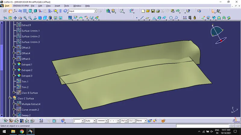
- Fillet the required surface and rename it as class B surface.
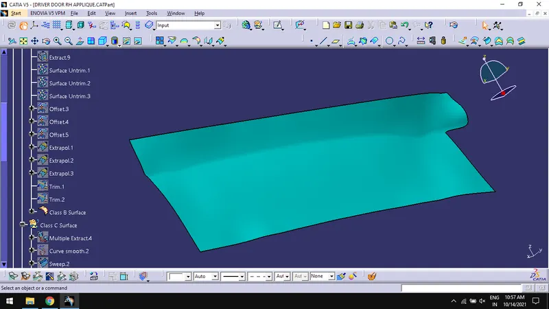
Create Class C Surface:
- Create a geometrical set, name it as Class C surface and multiple extract all the edges of the Class A surface.
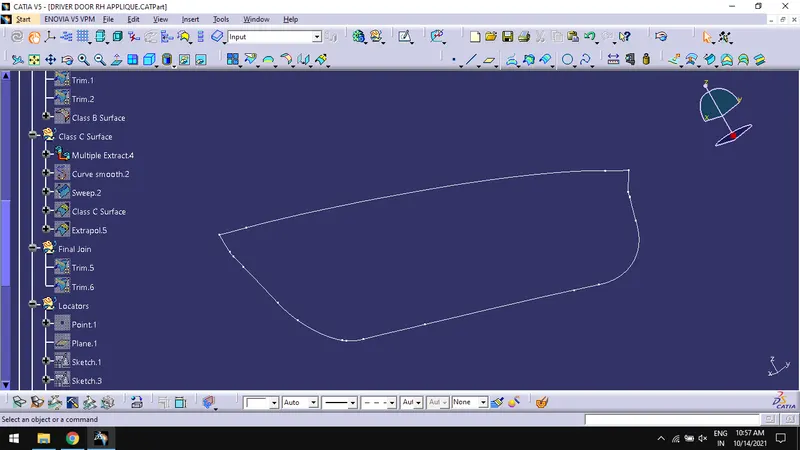
- Use smooth curve on extracted curve.
- Sweep the smooth curve with draft direction as tooling axis in 50
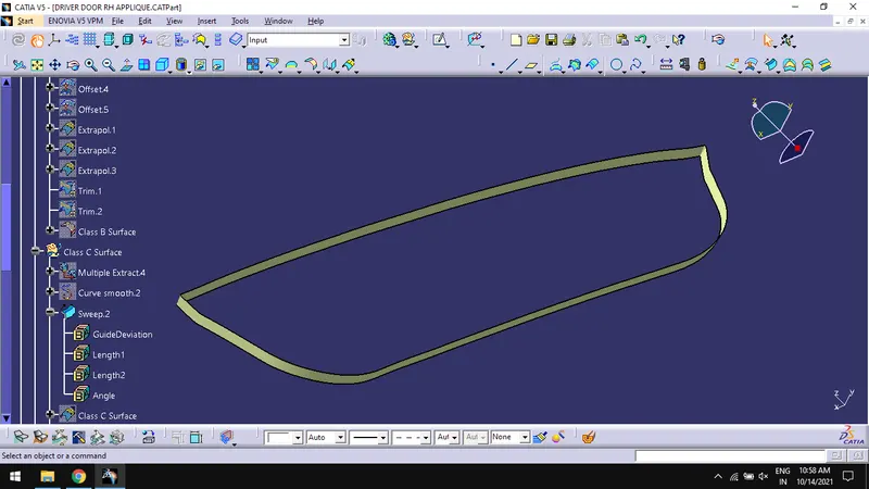
- Above swept surface is class C surface.
- Trim the class B with class C surface.
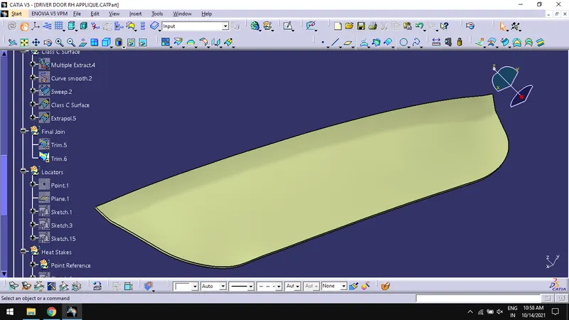
Solid Door Applique
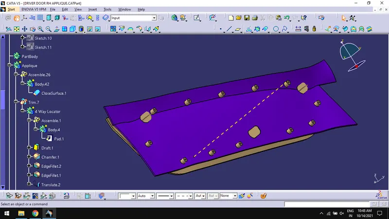
- In part design workbench, use close surface on the above trimmed surface to get solid door applique component.
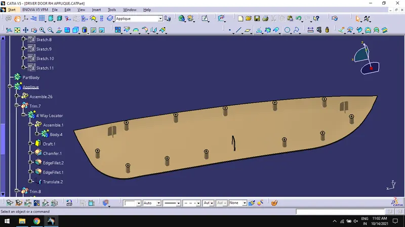
Create Locators
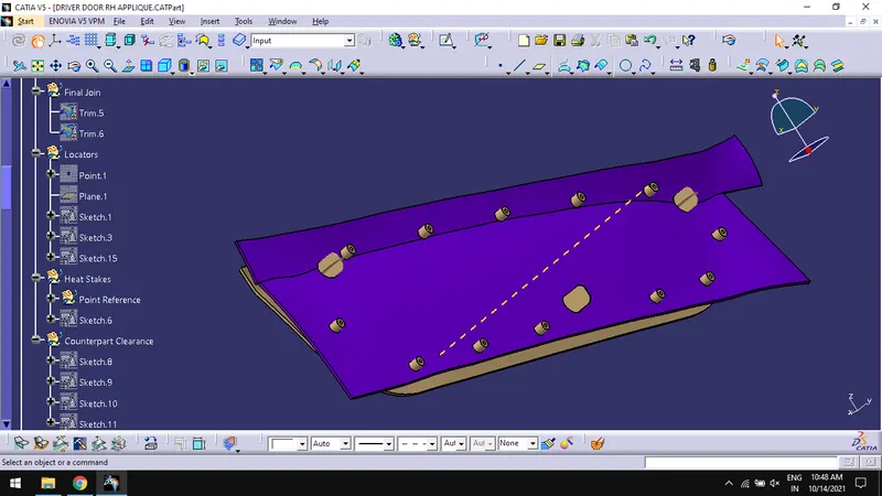
- Create a point on given counterpart surface and create a plane with point and ZX plane.
- Create the sketches with that plane for 4-way locator and 2-way locator.
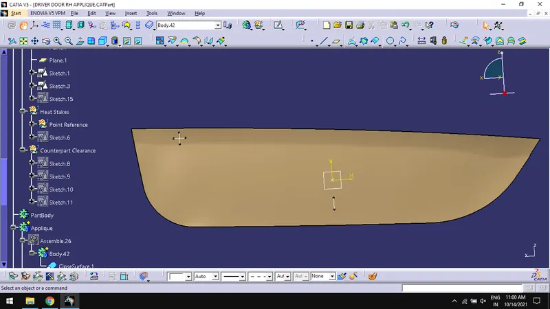
- In part design workbench, pad the sketches separately.
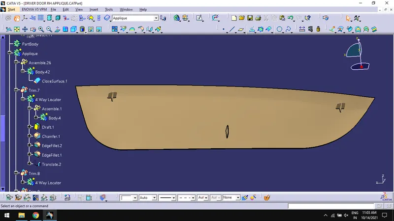
- Draft the body with tooling axis as pulling direction.
- Use chamfer and fillet on the body.
- Translate the body to required position.
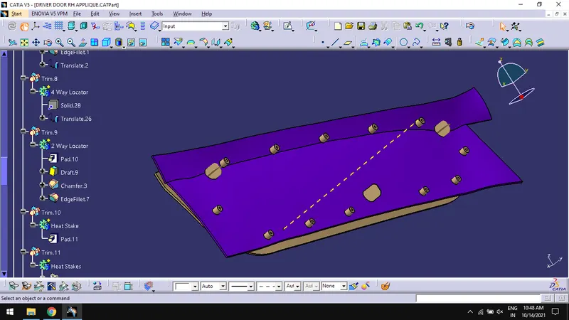
- Union trim the body with solid door applique and select surfaces to keep.
Create Heat Stakes
- Offset the class A surface for 2.5 mm and multiple extract the edges of offset surface.
- Use parallel curve on the extracted edges for 15mm inwards.
- Create reference points for heat stakes using point and plane repetition command and make sure there is adequate distance between locators and the point.
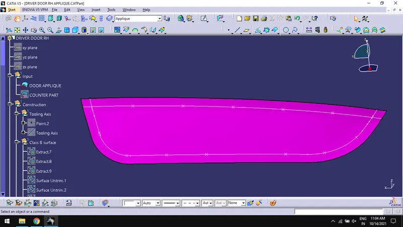
- Combine them in a geometrical set as point reference.
- Create a sketch using the reference points and previously created plane and draw the profile for heat stake.
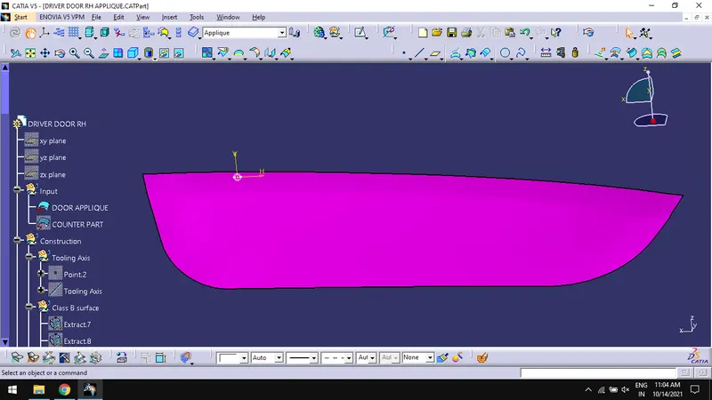
- In part design workbench, pad the sketch for required height, so that it can surpasses the door applique and counterpart.
- Use thick surface on the counterpart surface for 2mm.
- Draft and fillet the body of the heat stakes.
- Union trim the body with door applique and select surfaces to keep.
Create Counterpart Clearance:
- Create sketch with same points used for creating locators and heat stakes.
- Draw circular profiles on those point with 0.1mm clearance on both sides for locators and 0.5mm clearance for heat stakes and pad for required height.
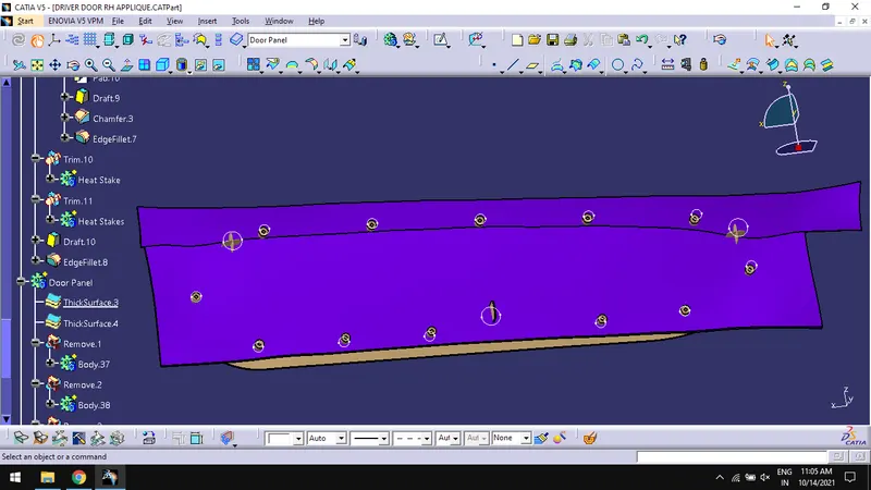
- Draft the body for 0.50 and tooling axis as pulling direction.
- Remove the bodies with door panel.
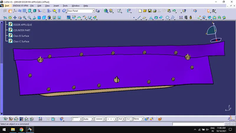
Tree Structure:
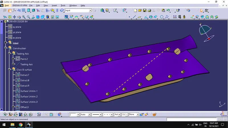
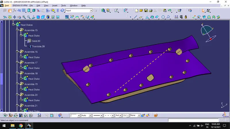
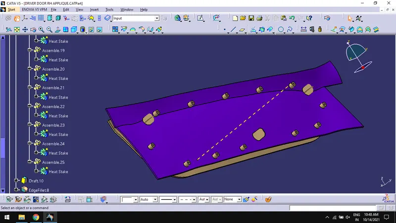
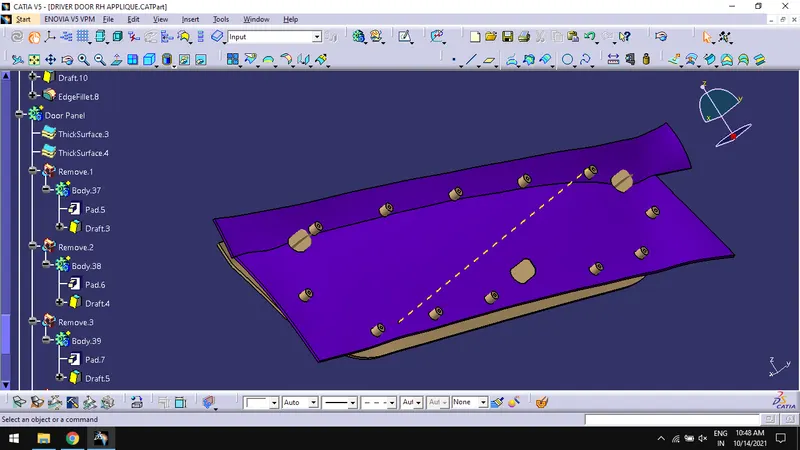
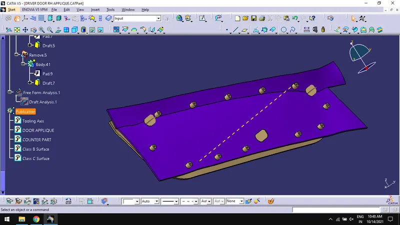
Draft Analysis:
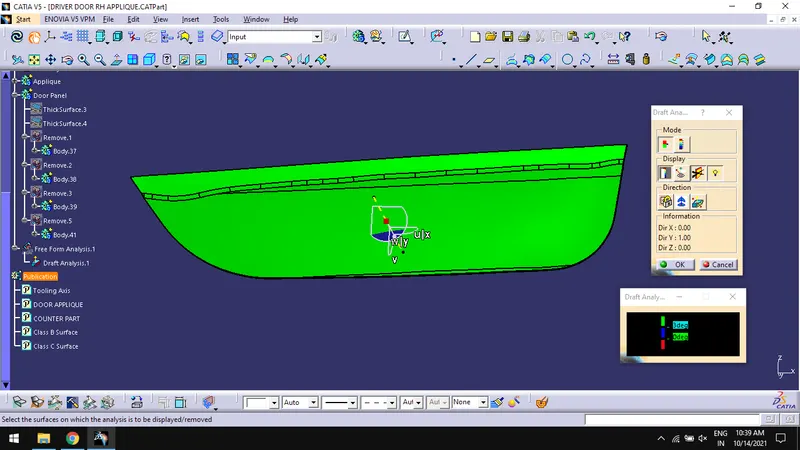
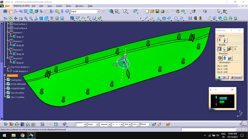
- Do draft analysis for final component with tooling axis following the general draft analysis procedure.
- To find Draft analysis option, Go to Insert > Analysis > Feature Draft Analysis.
Different Views of the part:
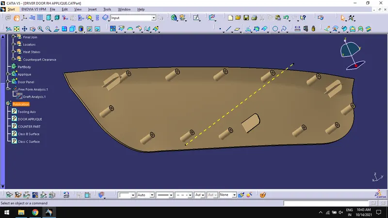
Isometric View:
Front View:
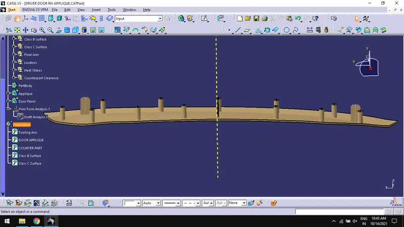
Side View:
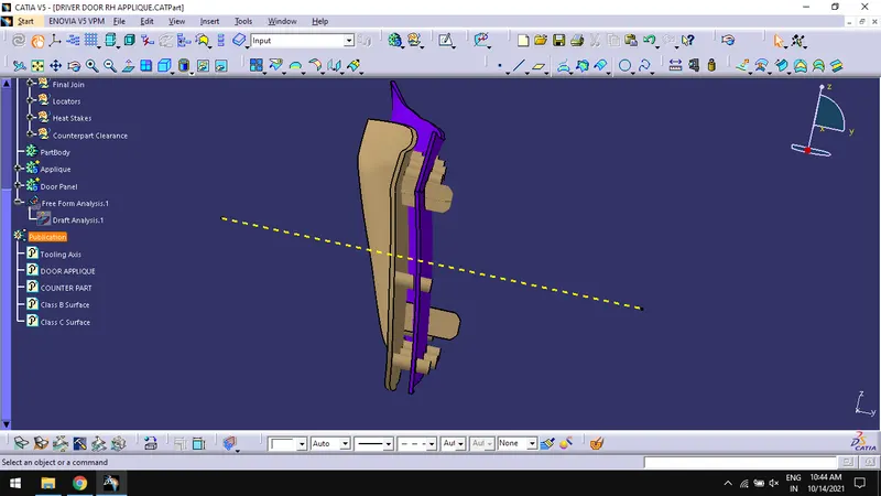
Top View:
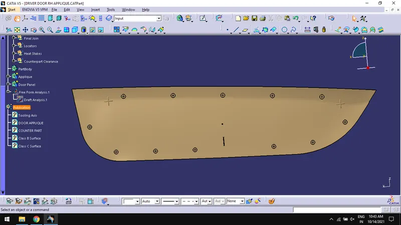
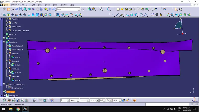
Conclusion:
Thus, creating the Door Applique Plastic component through the given Class-A surface along with Heat Stakes and the locators considering the design rules for the door applique and performing the Draft analysis on the model are done successfully.