Photo Realistic Rendering of American Chopper
PART MODELLING, ASSEMBLY AND PHOTO-REALISTIC RENDERING OF AMERICAN CHOPPER
OBJECTIVE:
- To design 3D models of parts of the chopper bike using solidworks.
- To assemble the parts of chopper bike to create a complete chopper bike model.
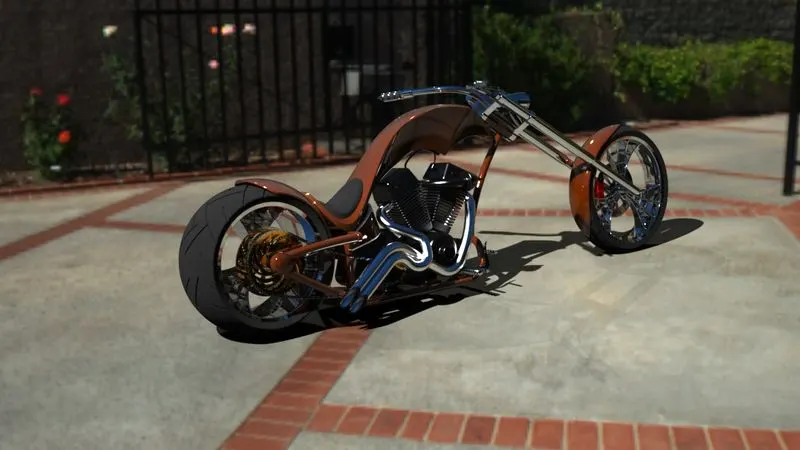
- To create a photorealistic rendering of chopper bike model using solidworks visualize and photoview 360.
INTRODUCTION:
This project explains designing of American chopper from individual part modelling to photo-realistic rendering. The tool used for designing is Solidworks 2020 and tool used for rendering is Solidworks visualize 2020.
FOLLOWING PARTS WERE MODELLED:
- Transmission belt
- Front fender
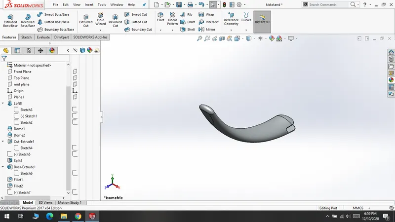
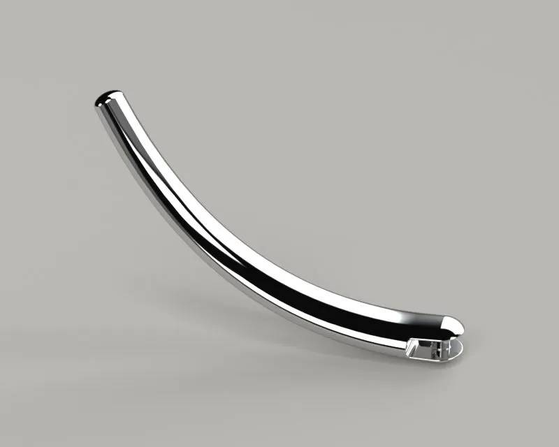
- Kickstand
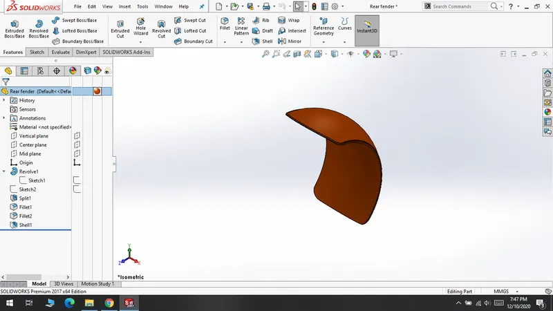
- Rear fender
- Chain
- Oil tank
- Pedal
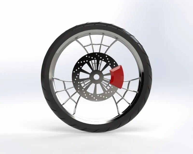
- Front wheel
- Front fork
- Rear wheel
- Engine
- Chassis
- Gas tank
DESIGN METHODOLOGY OF AMERICAN CHOPPER
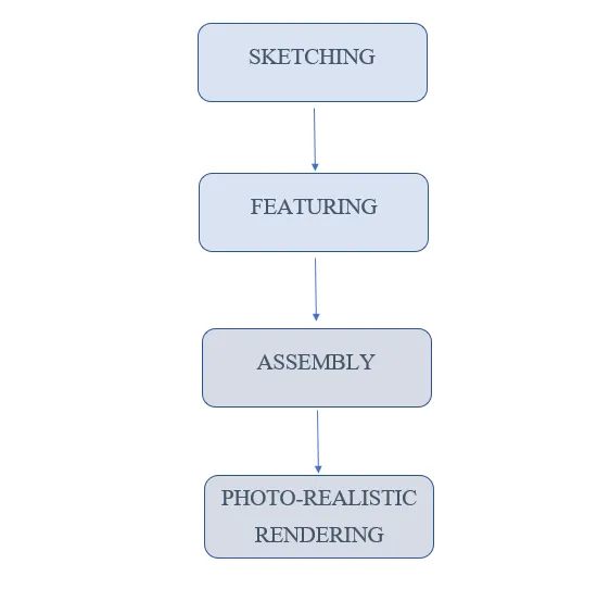
DESCRIPTION :
FEATURES USED IN PART MODELLING:
Sketching- a sketch is the base of 3D model
Convert entities - a tool allows users to make a copied projection of a given sketch, face or edges.
Trim – it is a handy tool to cut away a sketch geometry quickly.
Offset - Offset entities is a great tool for enlarging or shrinking your sketch geometry.
Mirror - Mirroring is another way that SolidWorks can create a “copy” of an existing object.
Extrude – it is used to extrude a base sketch into 3D model.
Revolve - This feature is used to revolve a 2D sketch along an axis or centerline.
Swept- Creates a sweep by moving a 2D profile along a 2D or 3D sketch path
Lofted- loft feature in solidworks allows you generate complex geometry in a single feature.
Extrude-cut - a handy feature to remove of a 3D model using 2D sketches.
Revolve-cut - Revolved cut removes materials by revolving a closed profile along an axis
Fillet - Fillet creates a rounded internal or external face on the part.
Chamfer- chamfer tool creates a beveled feature on selected edges, faces, or a vertex.
Shell- Shell feature hollows out the inside of the solid, leaving a shell of a specified wall thickness.
Reference geometry - it includes items such as planes, axes, coordinate systems, and points.
Curves – it is used to create several types of 3D curves such as projected curves and composite curves.
COMPONENTS WITH RENDERED IMAGES AND CAD IMAGES:
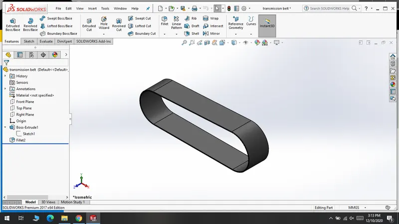
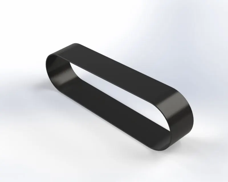
Transmission belt:
Features used to make :
- Sketch
- Extrude
- Fillet
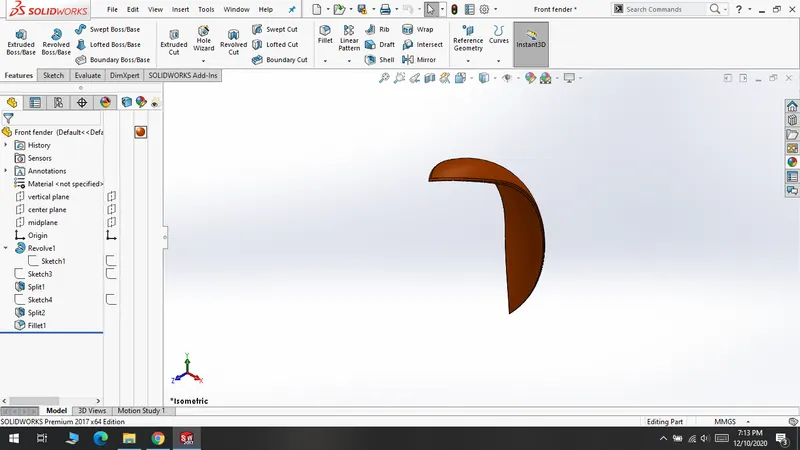
Front fender:
Features used to make :
- Sketch
- Revolve
- Split
- Fillet
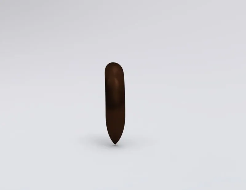
Kickstand:
Features used to make :
- Sketch
- Loft
- Dome
- Extrude
- Extrude- cut
- Split
Rear fender:
Features used to make :
- Sketch
- Revolve
- Split
- Fillet
- Shell
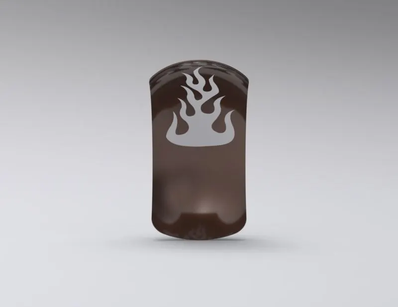
Chain:
Features used to make :
- Sketch
- Extrude
- Blocks
- Fillet
- Curve driven pattern
- Mirror
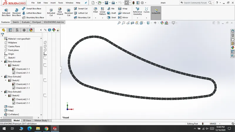
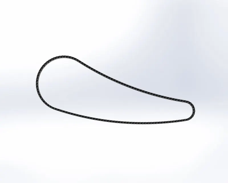
Oil tank:
Features used to make :
- Sketch
- Extrude
- Combine
- Fillet
- Shell
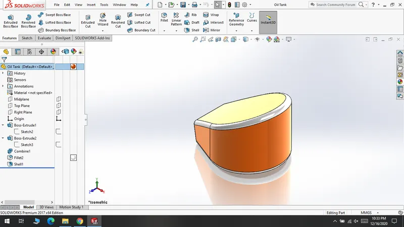
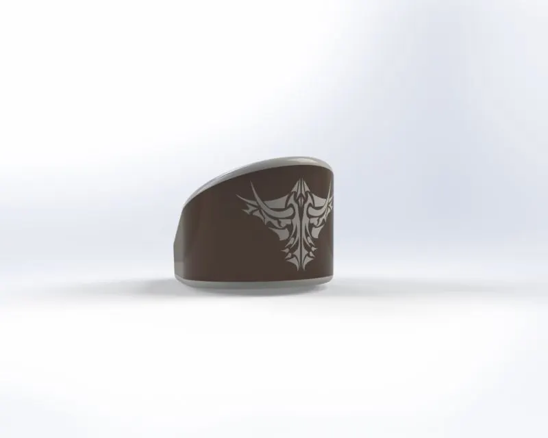
Pedal:
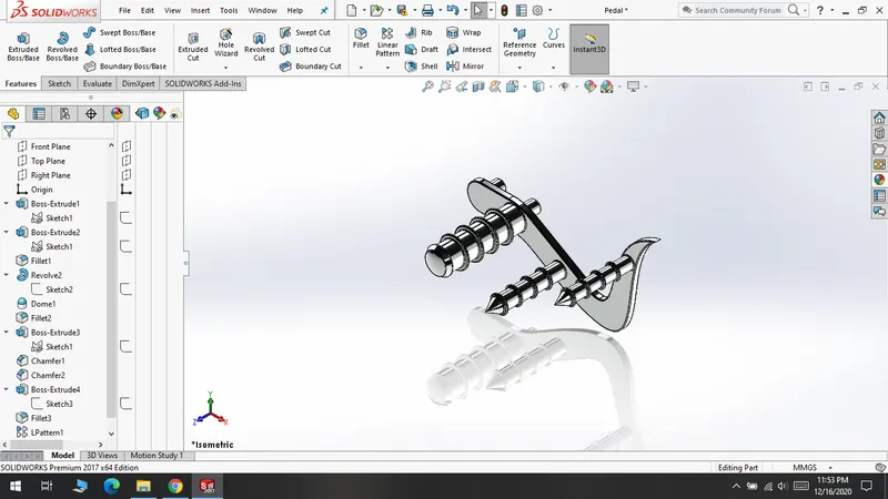
Features used to make :
- Sketch
- Extrude
- Fillet
- Revolve
- Dome
- Chamfer
- Linear Pattern
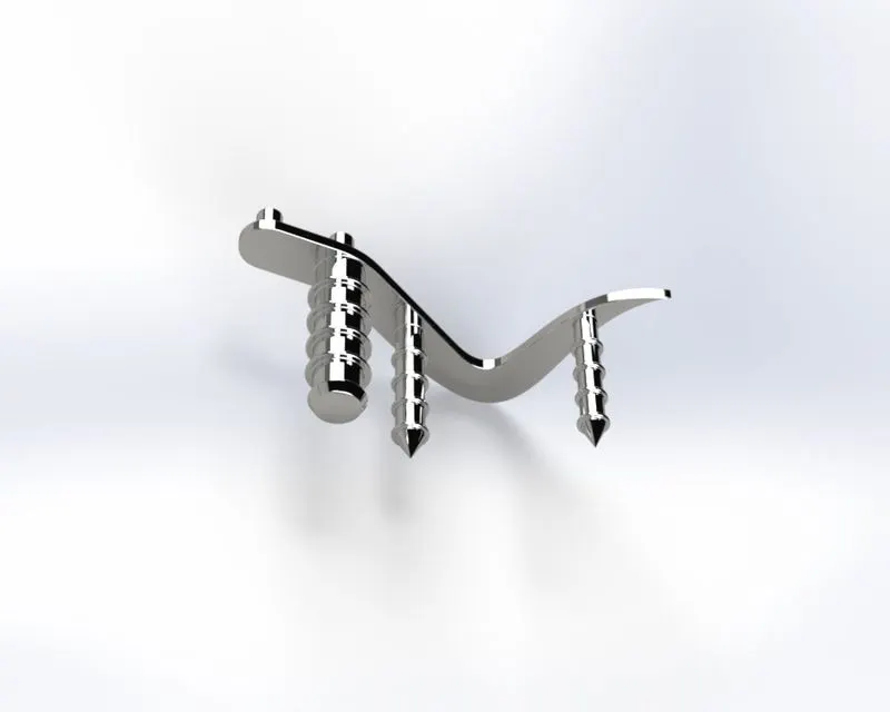
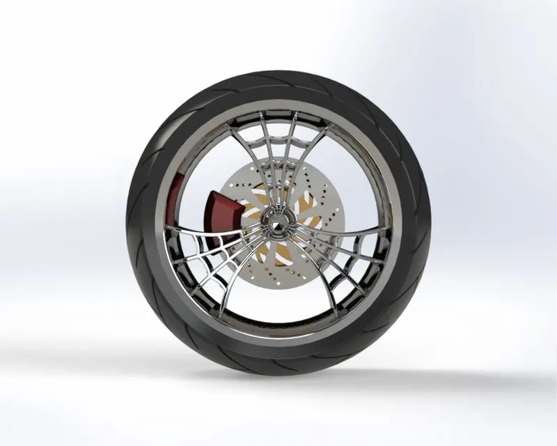
Front wheel:
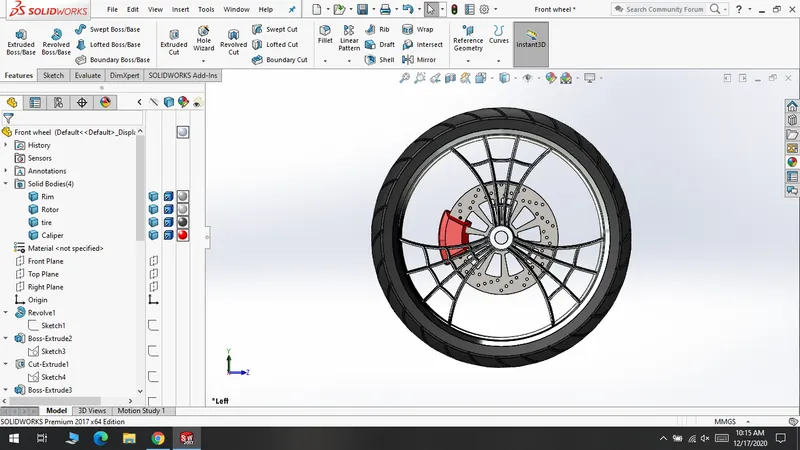
Features used to make :
- Sketch
- Extrude
- Revolve
- Extrude-cut
- Circular pattern
- Combine
- Fillet
Front fork:
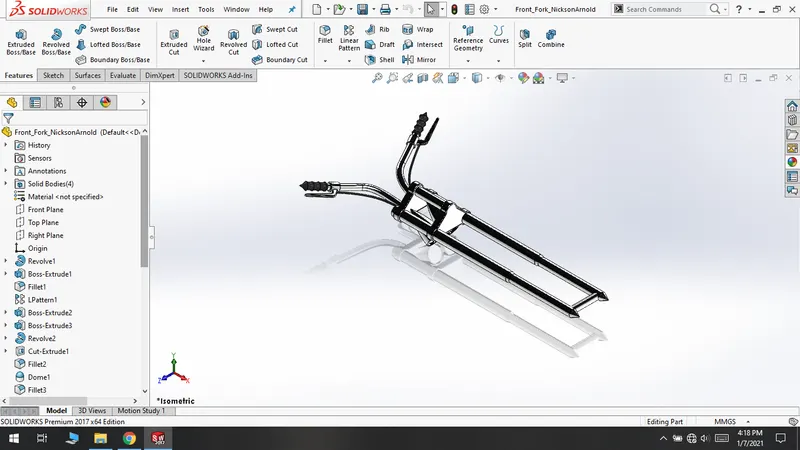
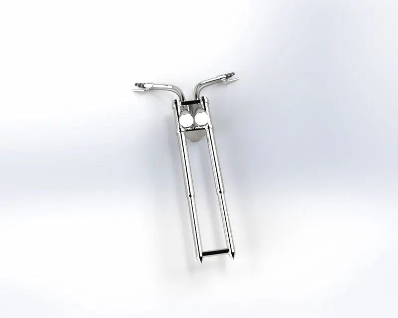
Features used to make :
- Sketch
- Extrude
- Revolve
- Fillet
- Linear pattern
- Extrude-cut
- Revolve- cut
- Swept
- Dome
- Mirror
- Combine
Rear wheel:
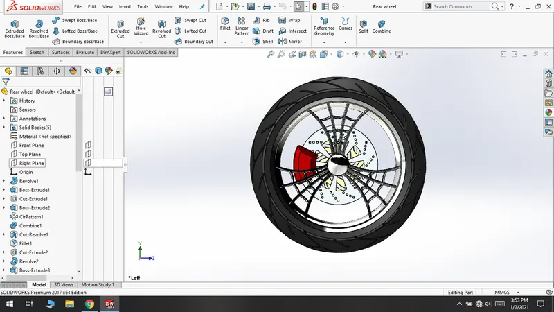
Features used to make :
- Sketch
- Extrude
- Revolve
- Extrude-cut
- Fillet
- Circular pattern
- Champer
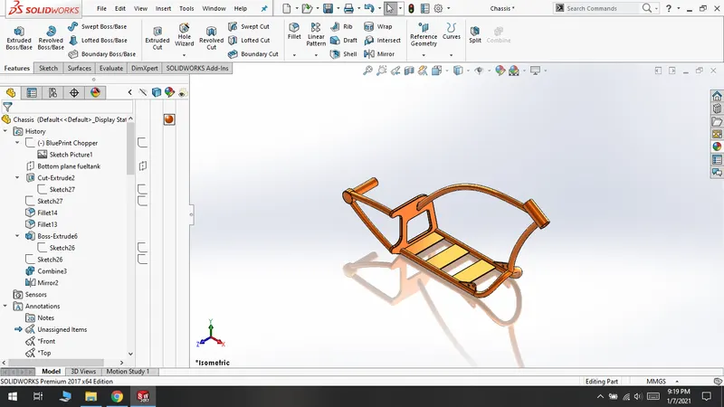
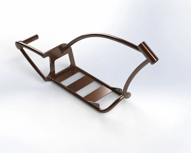
Chassis:
Features used to make :
- Sketch
- Extrude
- Curve
- Sweep
- Mirror
- Extrude-cut
- Champer
- Fillet
- Dome
- Split
- Combine
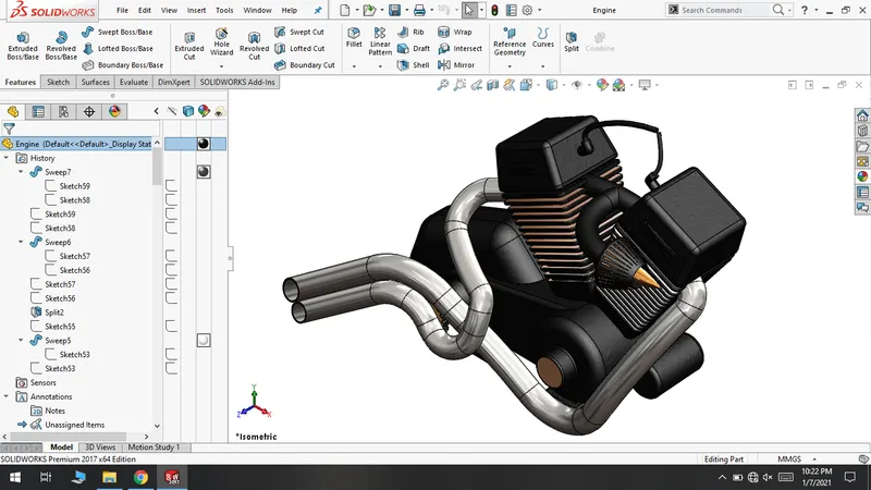
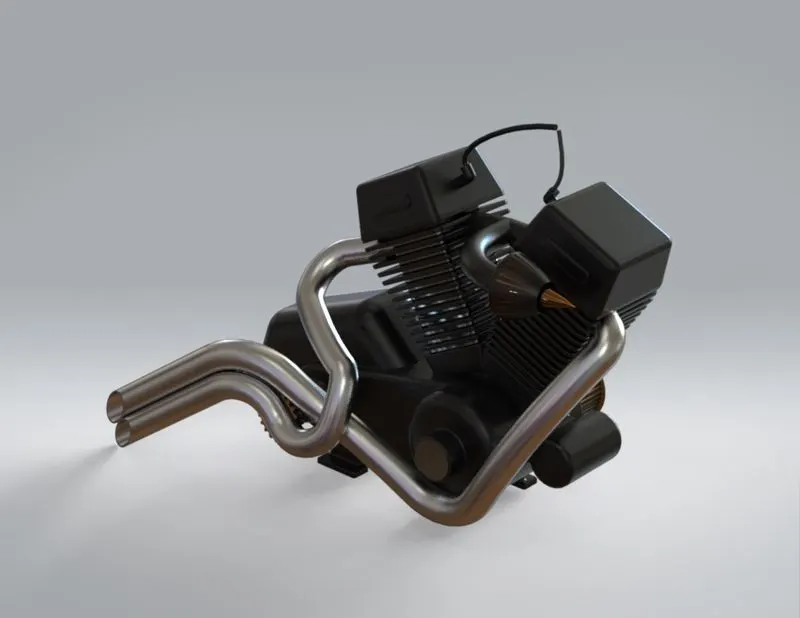
Engine:
Features used to make :
- Sketch
- Extrude
- Revolve
- Sweep
- Split
- Fillet
- Champer
- Linear pattern
- Dome
- Mirror
- Combine
- Composite curves
Gas tank:
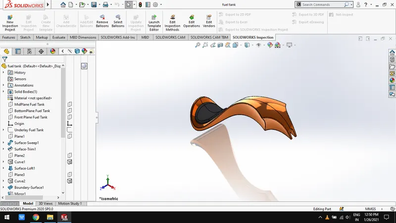
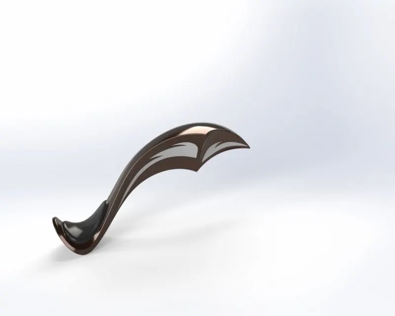
Features used to make :
- Sketch
- Sweep – surface
- Trim – surface
- Loft – surface
- Curves
- Mirror
- Knit – surface
- Split
- Fillet
- Shell
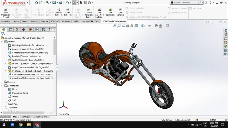
ASSEMBLY OF AMERICAN CHOPPER :
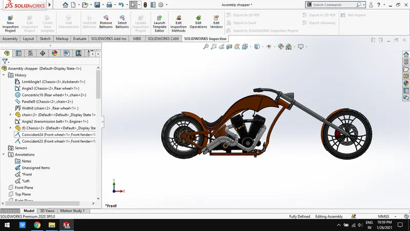
Features used for assembly:
- Mates – coincide, concentric , limt- angle, position, parallel etc.
- Insert parts
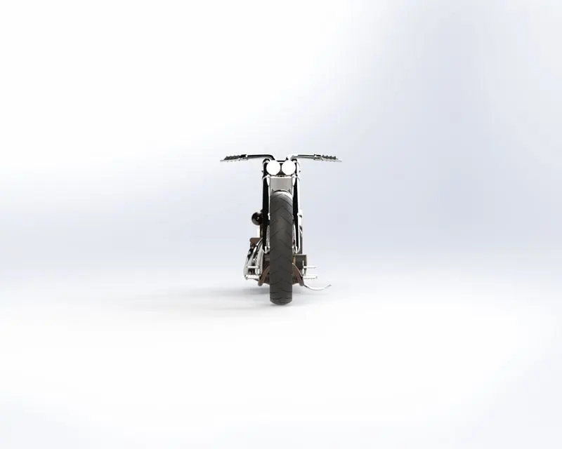
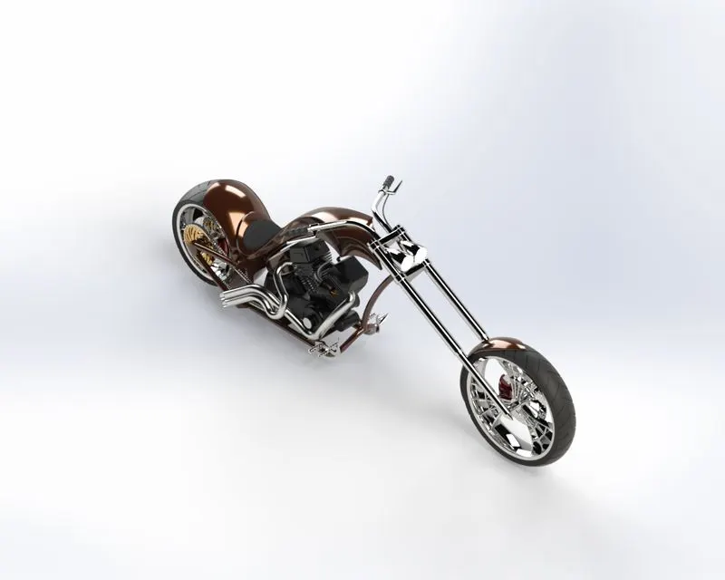
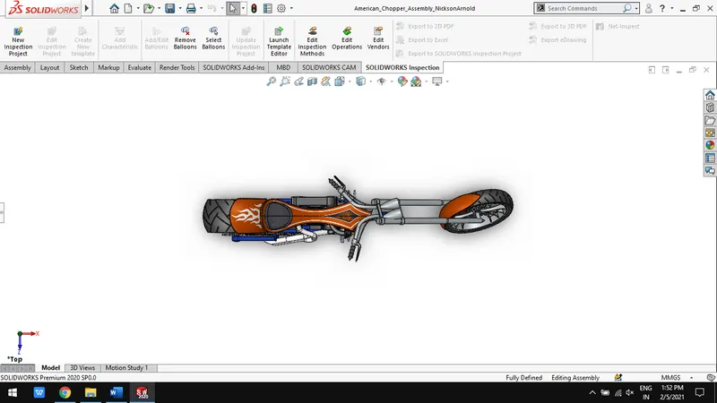
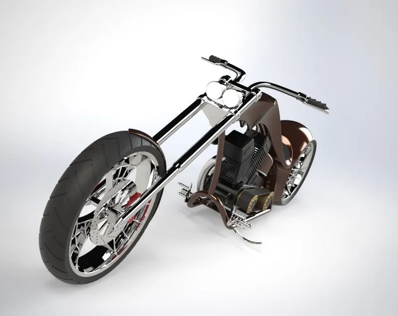
CAD MODELS AND RENDERED MODELS IMAGES:
Front view:
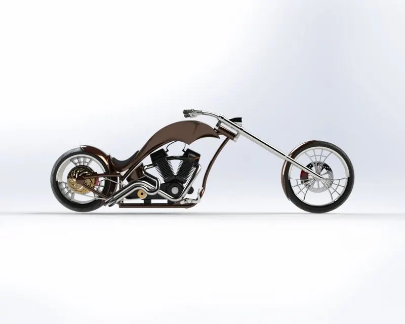
Leftside view:
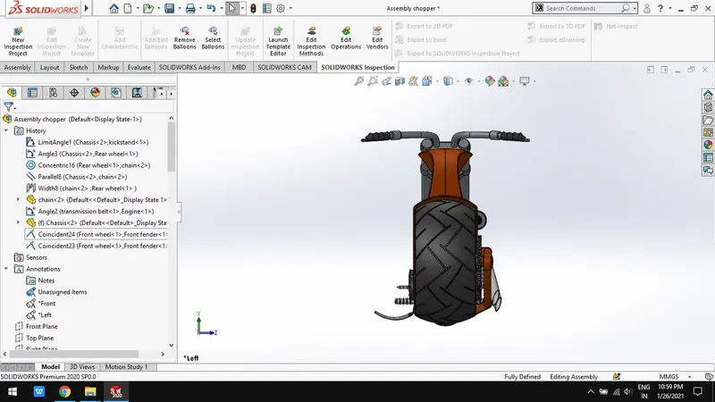
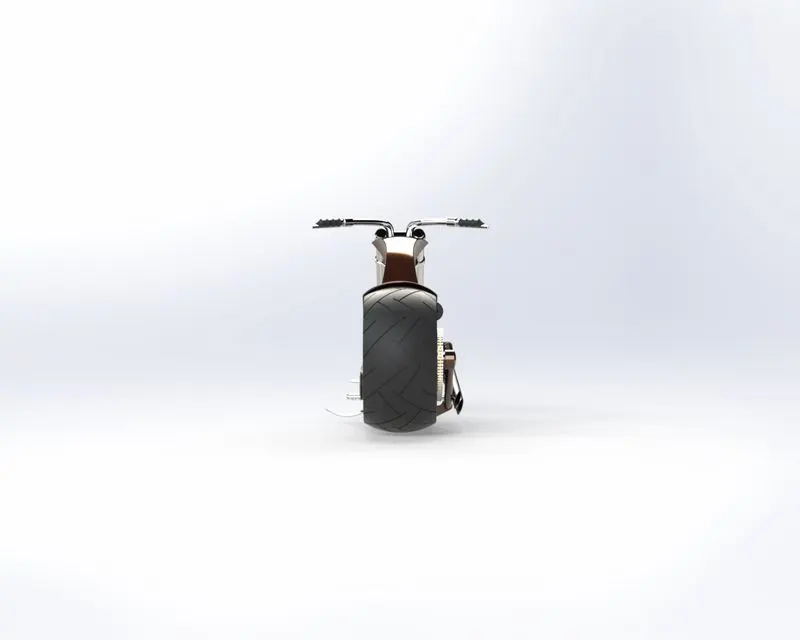
Rightside view:
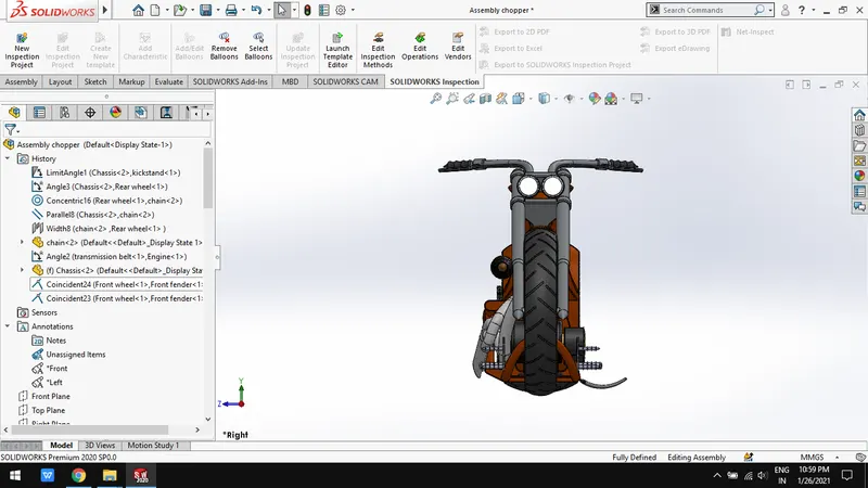
Isometric view:
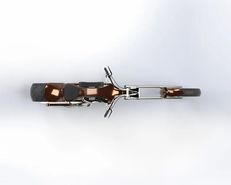
Top view
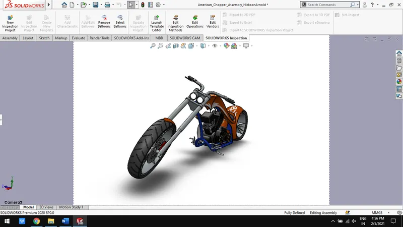
Camera setup view:
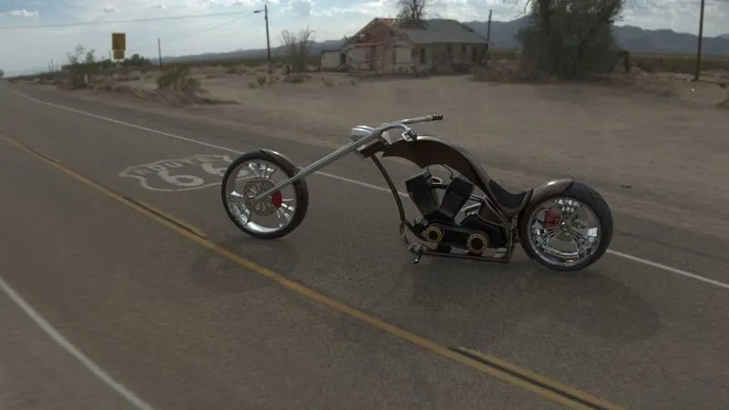
RENDERED WITH ENVIRONMENT:
Conclusion:
- Thus, the parts of American chopper are modelled using solidworks.
- The parts are assembled to create a complete model of American chopper.
- The photo-realistic images of American chopper are rendered using solidworks visualize and photoview 360.