Week 9 - Project - Master Section Development
Aim:
To design a B – pillar from given class A surface and master section into a plastic component with engineering features and perform draft analysis on the component.
Objectives:
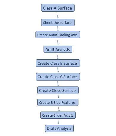
- To create the tooling axis for the component.
- To create required flanges, class B and Class C surface.
- To create engineering features such as dog house, locators and ribs.
Introduction:
B – Pillar trim:
The B-pillar is the central pillar of the car. This pillar is actually a sheet metal part which is welded in the BIW of the car. The B-pillar trim is attached to the B-pillar and improves the aesthetic look of the car. Mostly the trims are manufactured by the injection molding process.
Master section:
Master sections are the guides for design requirements which shapes the component after technical styling after technical styling of class A surface.
Methodology:
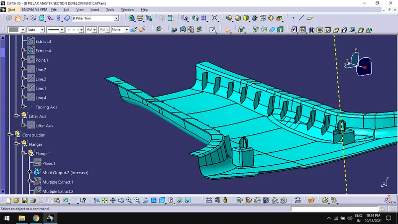
Creation of Tooling Axis:
- Extract the edges of locators in master section.
- Create a point between the vertices of the edges.
- Draw lines using point- point option on the extracted edges.
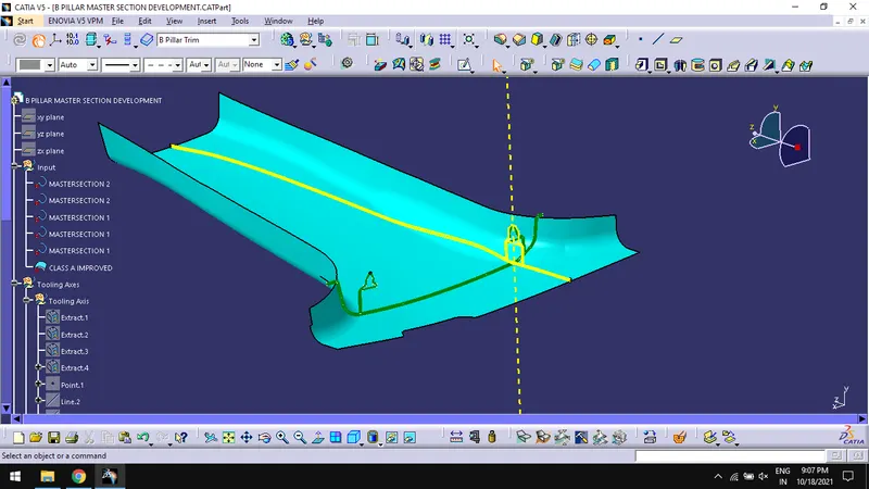
- Draw a line bisecting the above lines and rename it as tooling axis.
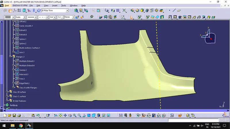
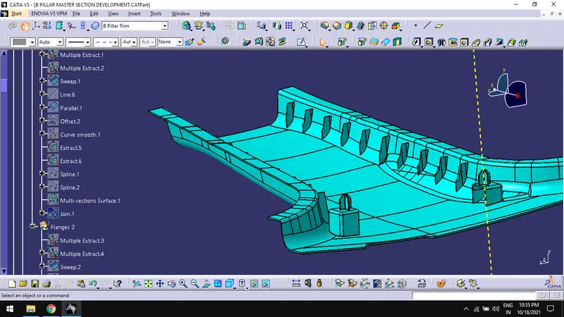
Creation of Flanges:
- Create a plane on the master section with 3 points.
- Create a sweep on the edges of the class A surface using extracted edges by multiple extract command.
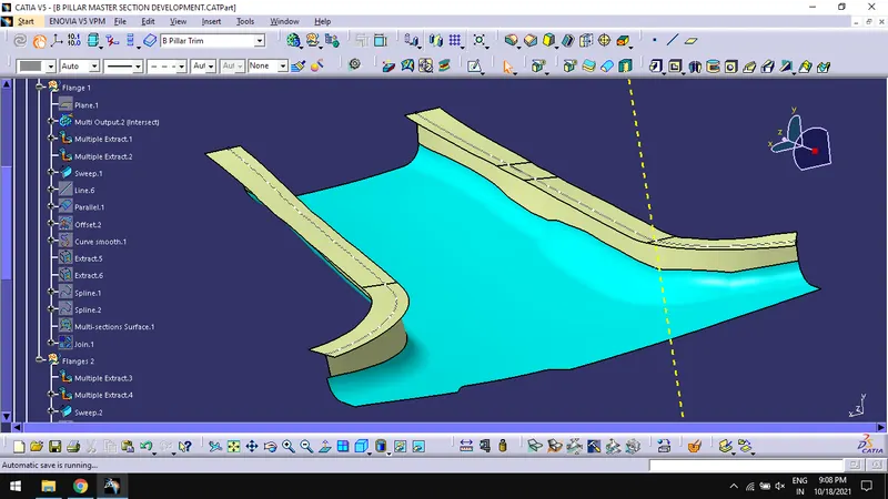
- Check the sweep by intersecting the master section with plane created.
- Offset the sweep based on the intersect.
- Trim the class A with sweep.
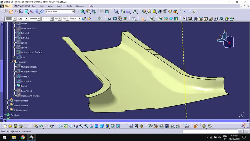
- Create edge fillets on the edges and rename it as Class A with Flanges.
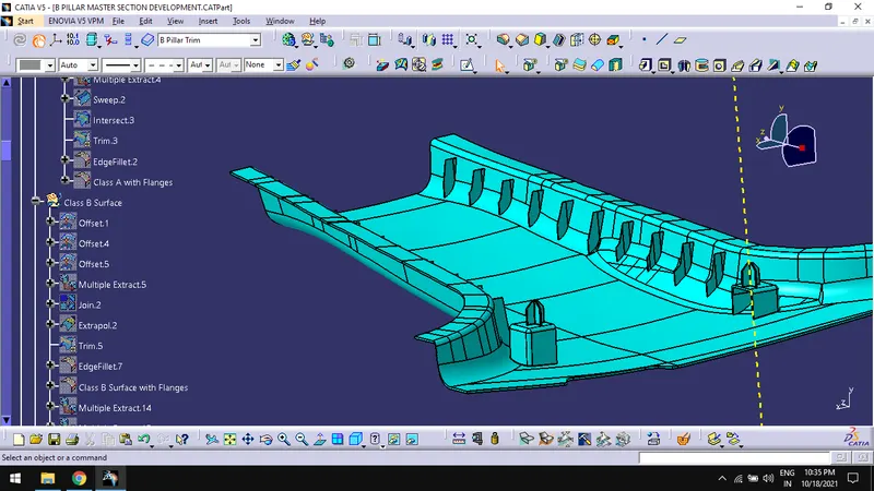
Creation of Class B Surface:
- Create a geometrical set, name it as Class B surface and extract the surfaces of class A using extract command.
- Offset the surface for 2mm.
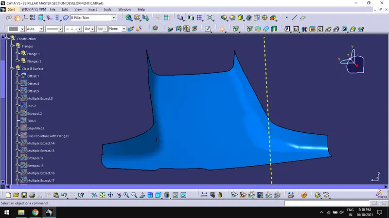
- Offset the flanges for 2mm.
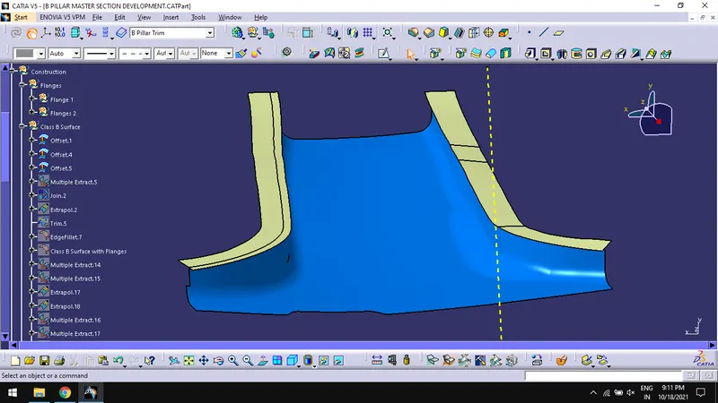
- Extrapolate and trim the flanges with class B surface.
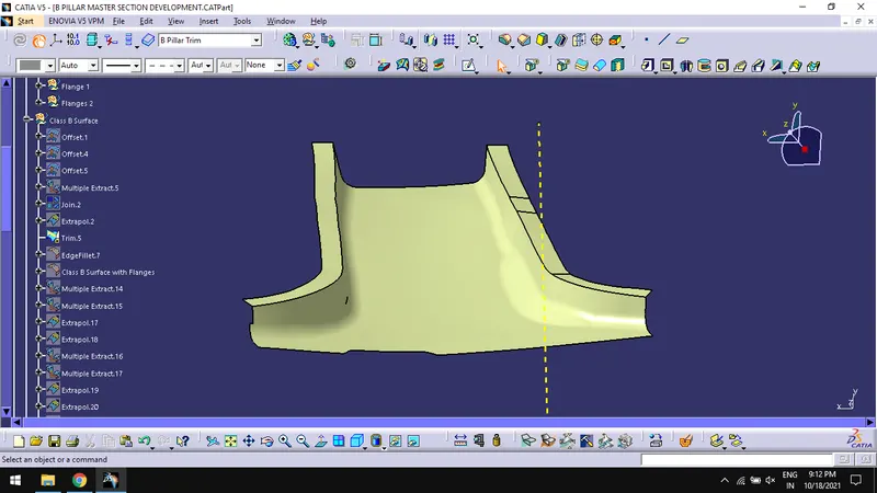
- Create fillets on the edges.
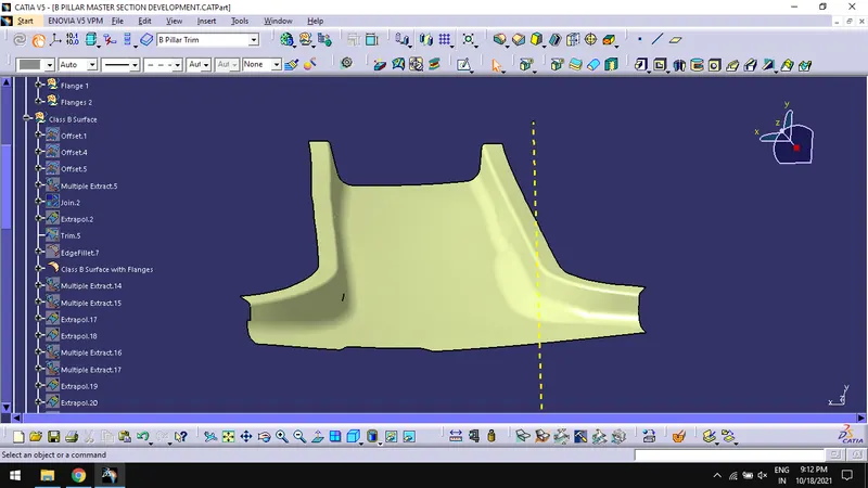
Creation of Class C Surface:
- Extract the edges of class A surface with flanges using multiple extract.
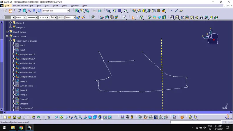
- Sweep the extracts with draft direction as tooling axis.
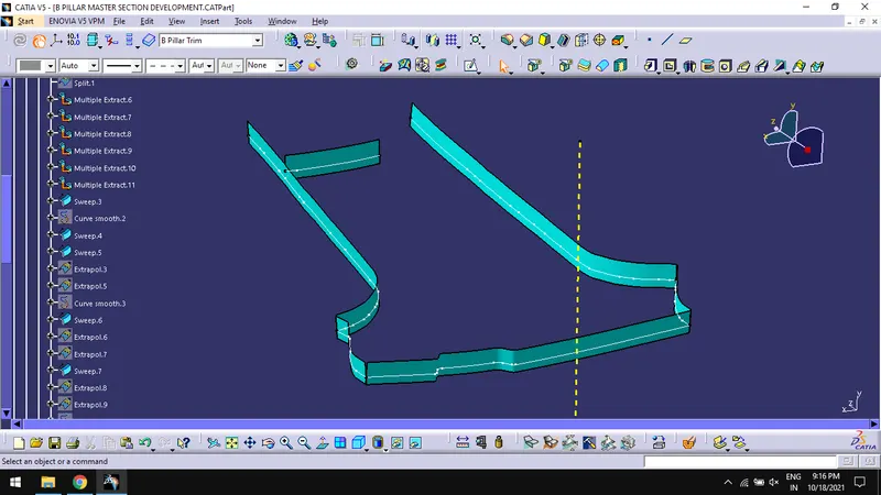
- Extrapolate the sweeps to create class C surface.
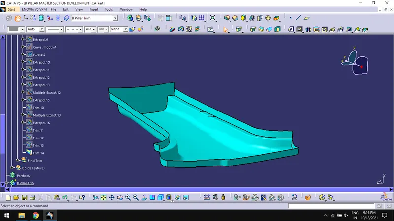
- Trim the class C surface with class B surface.
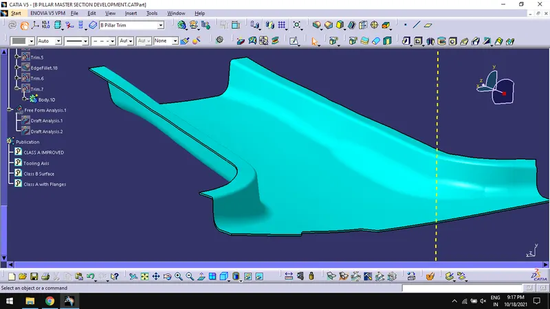
Creation of solid Component:
- In part design workbench, use close surface command on the surface to create solid plastic component.
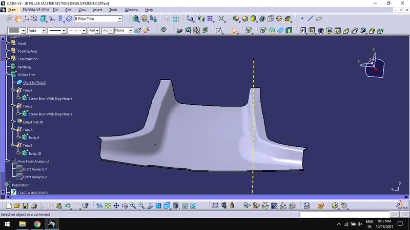
Creation of B Side Features:
- Dog House
- Creation of B side features include creation of dog house, locators and ribs.
- Create point and plane based on the master section location for dog house.
- Extract the master section for the dog house.
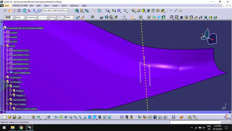
- Create the sketch and extrude for the dog house surface.
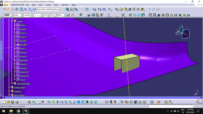
- Extrapolate and trim the surface to get the required surface.
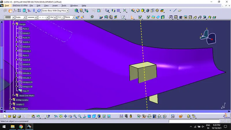
- Use thick surface command on the surface to get the solid dog house.
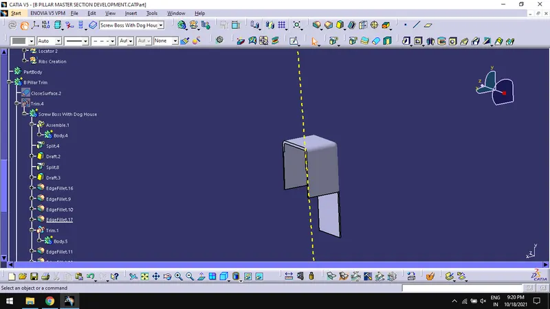
- Locators
- Create the plane and sketch for locator using the plane.
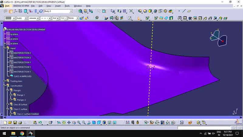
- Pad the sketch to get locator body.
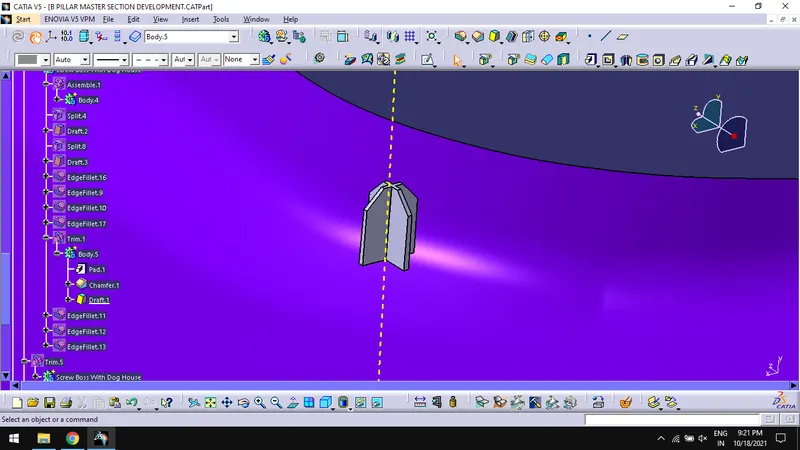
- Chamfer and fillet the locator solid.
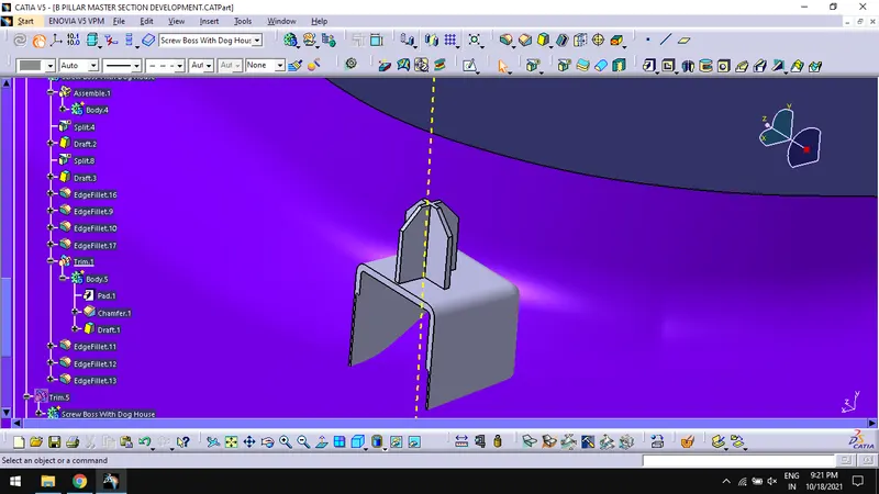
- Trim the body with dog house and select the required surface for the surfaces to keep.
- Ribs
- Create sketch for the ribs.
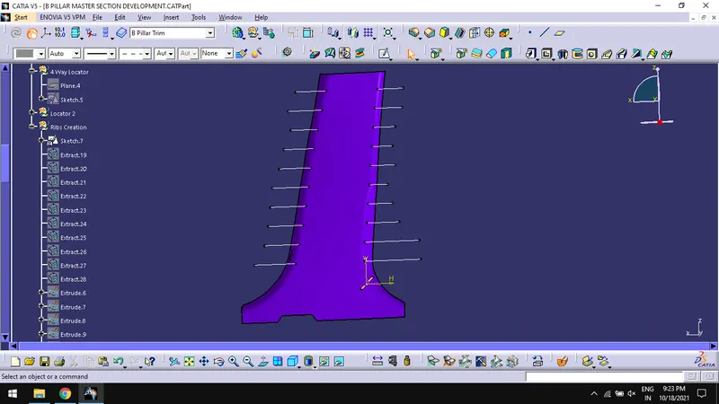
- Extract and extrude separately in tooling axis direction.
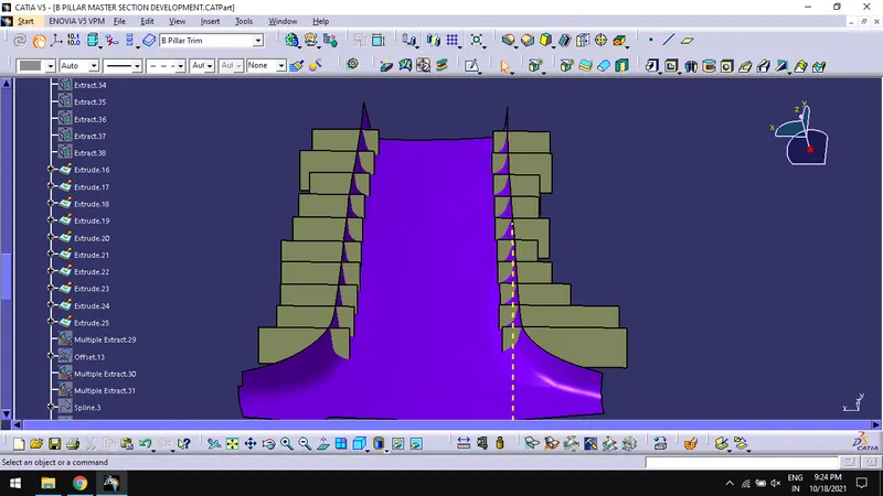
- Thick surface the extruded surface for 0.8mm
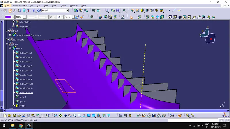
- Multiple extract the surfaces around the rib extrudes.
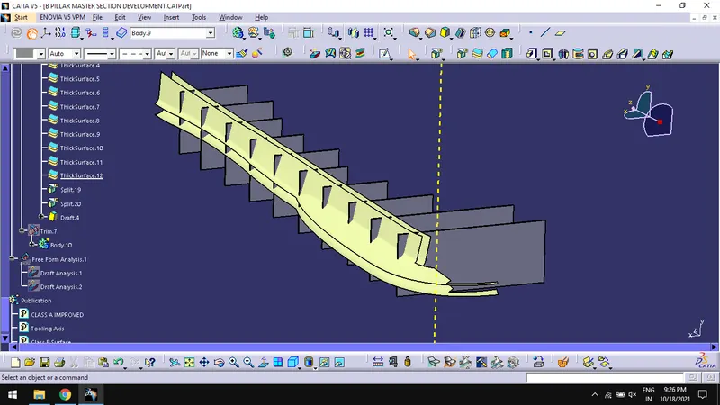
- Split the ribs bodies with multiple extract.
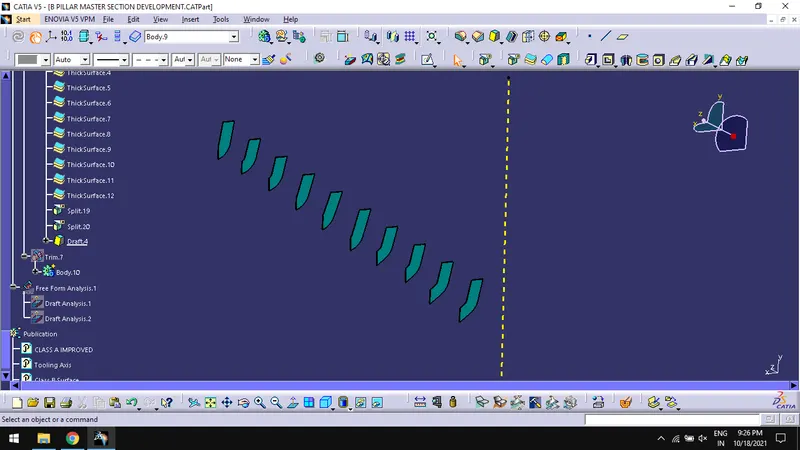
- Draft the ribs for 0.50 in tooling axis direction.
- Trim the bodies with B- pillar trim.
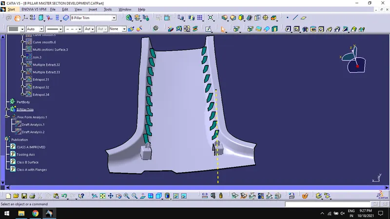
Creation of Lifter Axis:
- Create a line using point and plane used in creating dog house and rename it as lifter axis.
Draft Analysis:
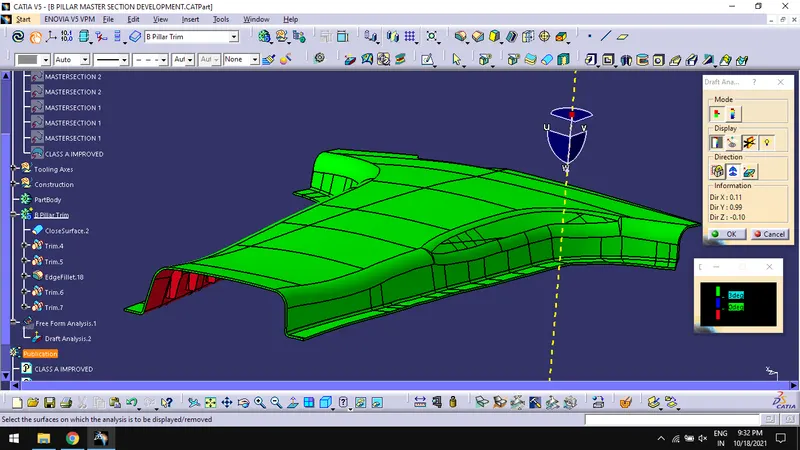
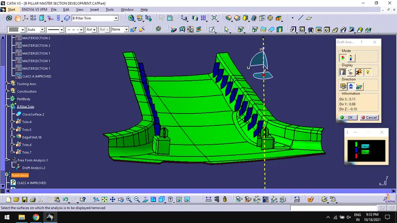
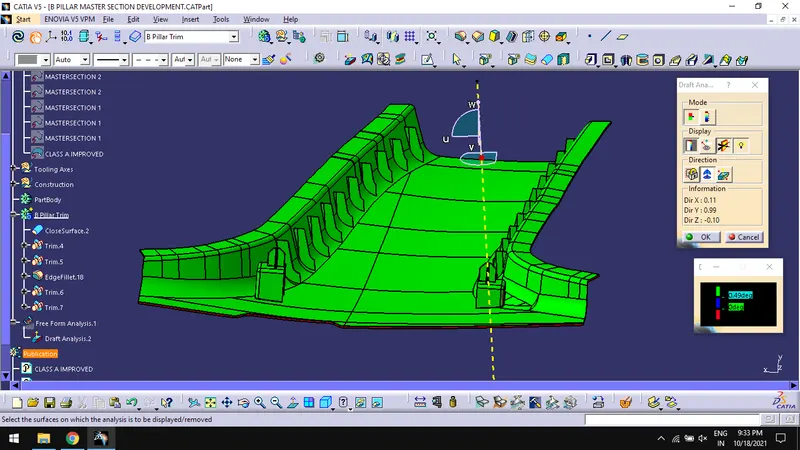
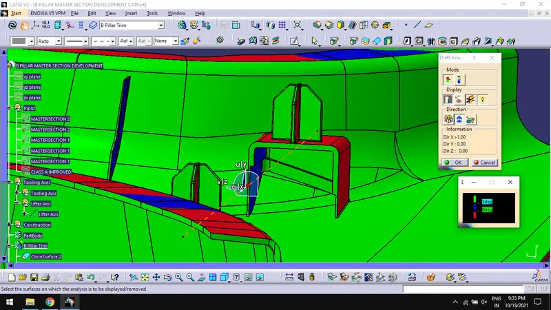
- Do draft analysis for final component with tooling axis following the general draft analysis procedure.
- To find Draft analysis option, Go to Insert > Analysis > Feature Draft Analysis.
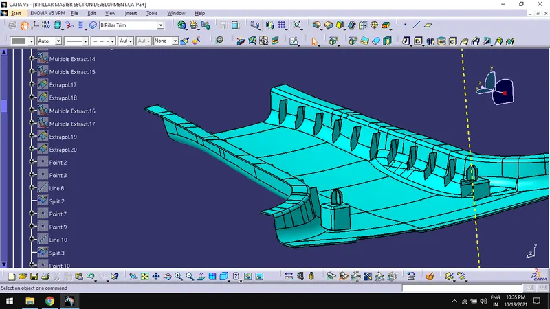
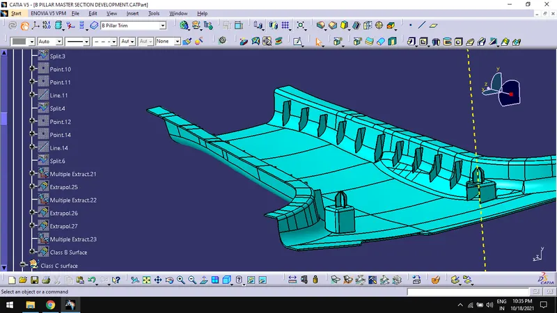
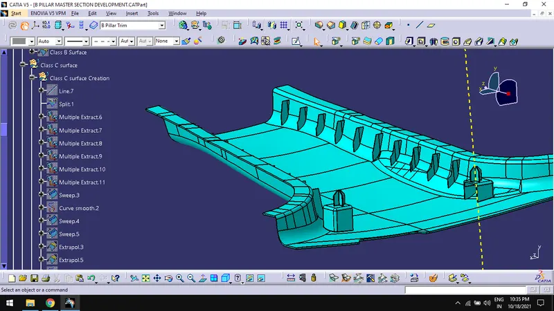
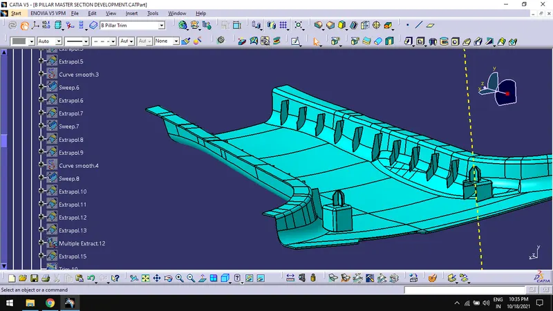
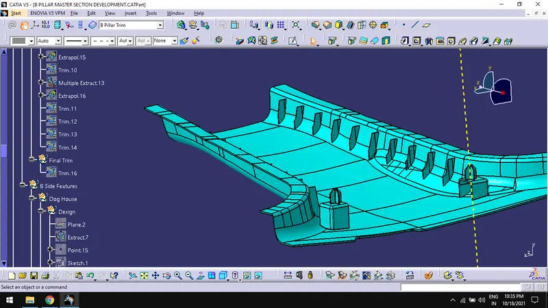
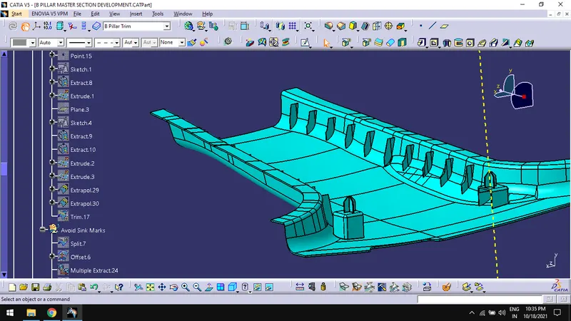
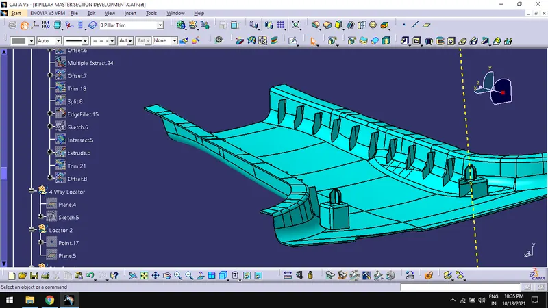
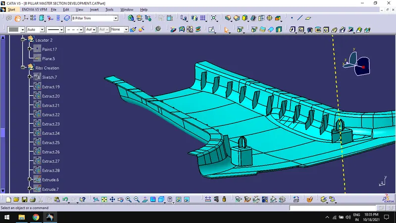
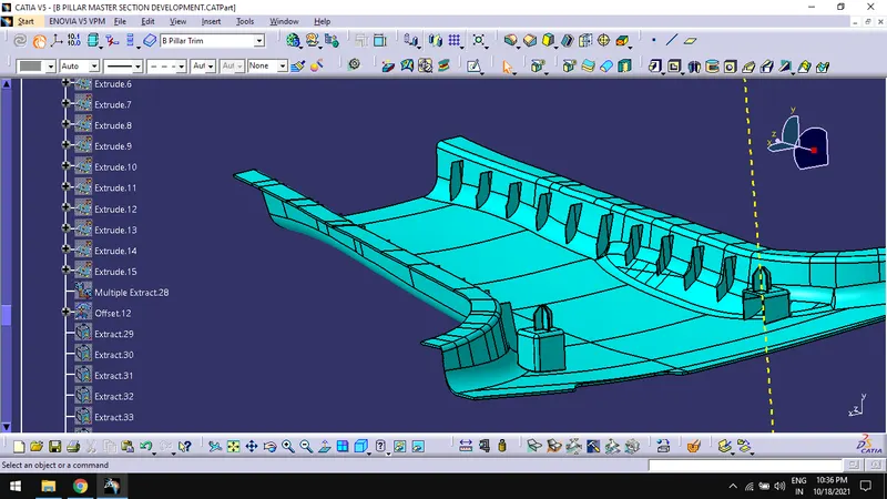
Tree Structure:
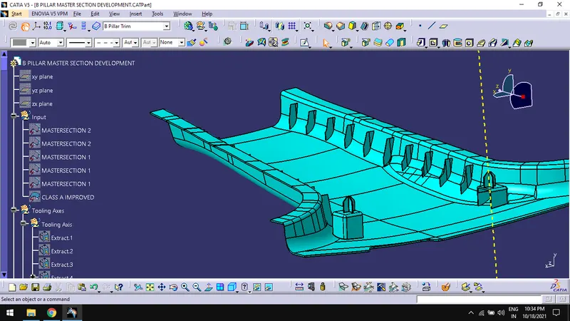
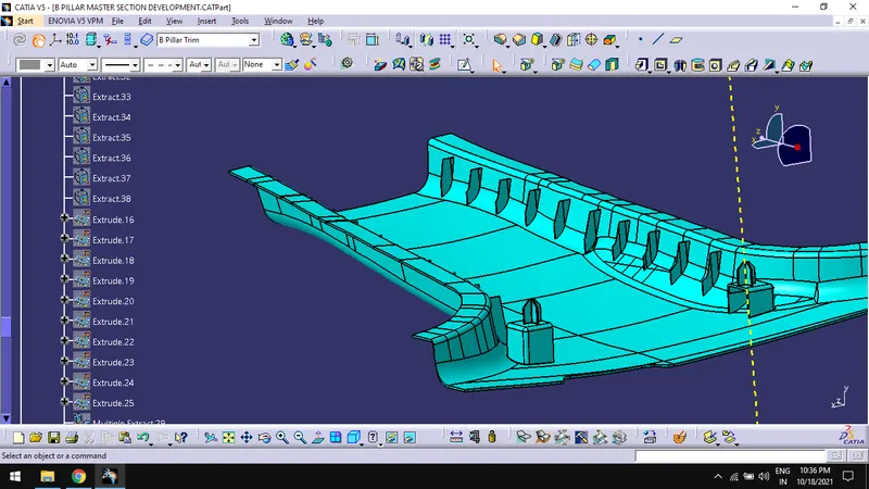
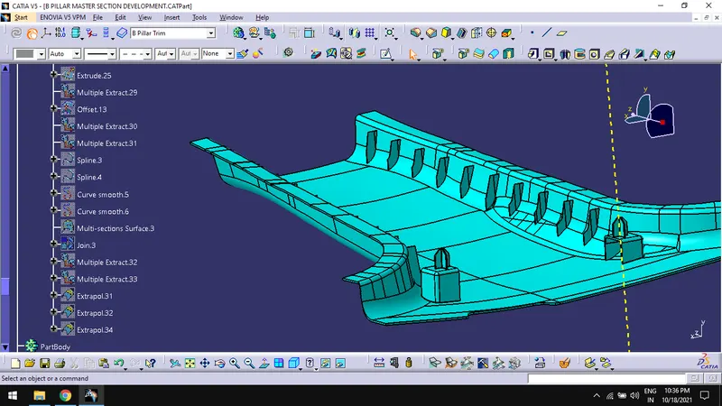
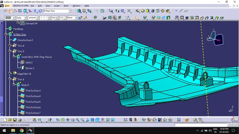
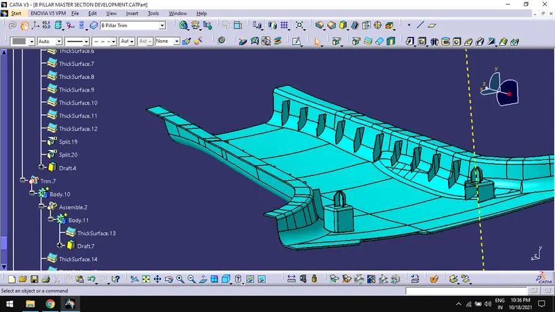
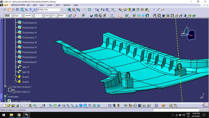
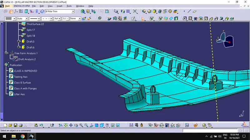
Different views of the component:
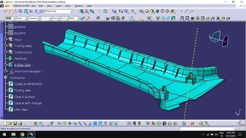
Isometric view:
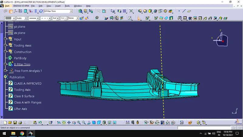
Front view:
Side view:
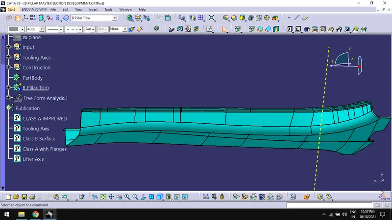
Top view:
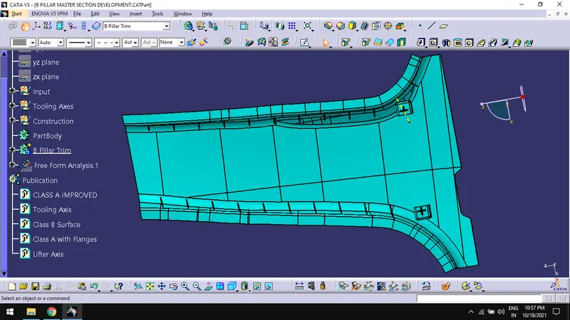
Conclusion:
Thus, designing a B – pillar from given class A surface and master section into a plastic component with engineering features and performing draft analysis on the component are done.