Week - 4
WASHING MACHINE:
AIM:
- Implement control logic of a “washing machine” using State flow as per given sequence:
- If the power supply is available, the system gets activated
- If the Water supply is not available, stop the process & indicate through LED
- Soaking time should be 200s followed by Washing time of 100s.
- Then rinsing happens for next 20s & dryer runs for 50s
After all the processes have completed turn on the finished LED.
Introduction:
Simulink:
Simulink is a MATLAB-based graphical programming environment for modeling, simulating and analyzing multidomain dynamical systems. Its primary interface is a graphical block diagramming tool and a customizable set of block libraries. It offers tight integration with the rest of the MATLAB environment and can either drive MATLAB or be scripted from it. Simulink is widely used in automatic control and digital signal processing for multi-domain simulation and model-based design.
Control logic:
Control logic is a paramount part of a software program that controls the operations of the program. The control logic answers to commands from the user, and it also acts on its own to execute automated tasks that have been structured into the program. It is also known as the controller and is part of the underlying software architecture developed at the same time that the program is designed and coded.
Stateflow:
Stateflow provides a graphical language that includes state transition diagrams, flow charts, state transition tables, and truth tables. A Stateflow chart can utilize MATLAB or C as the action language to implement the control logic. We can also represent stateless flow charts.
Procedure:
- A Chart is created in the Simulink for the washing machine processes as shown below.
- Variables are connected to denote power and water supply.
- Rocker switch is connected to control the power and water supply.
- Power and water supply is connected to the chart as inputs.
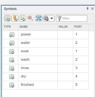
- Taking the inputs, the chart gives the outputs such as soaking, washing, rinsing, drying and finished.
- These outputs are connected to terminators. So that lamps can be connected to it.
- Using the lamps, completion of each process is indicated.
Simulink Model:
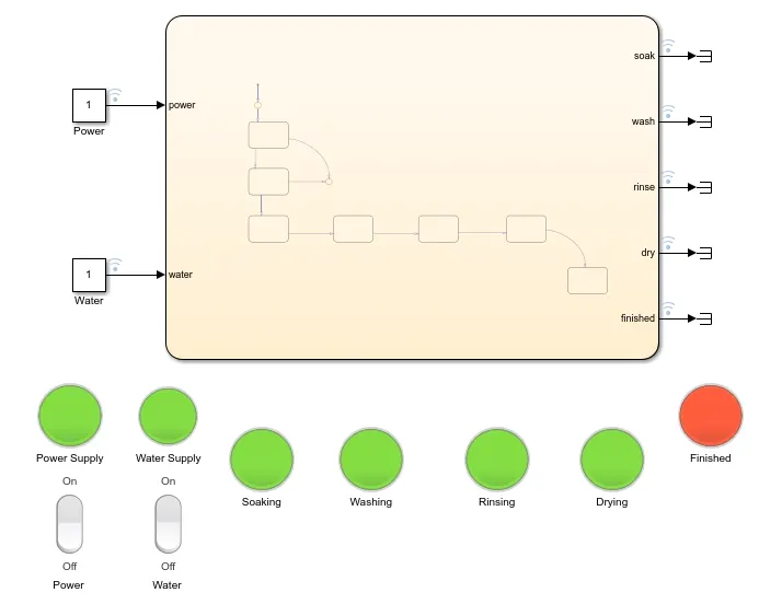
Chart:
Working sequence:
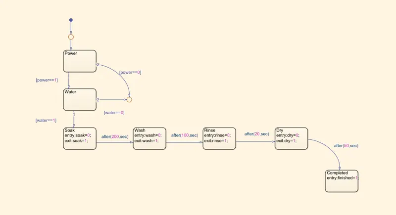
- If the power supply is available, the system gets activated
- If the Water supply is not available, stop the process & indicate through LED
- Soaking time should be 200s followed by Washing time of 100s.
- Then rinsing happens for next 20s & dryer runs for 50s
- After all the processes have completed turn on the finished LED.
case 1:
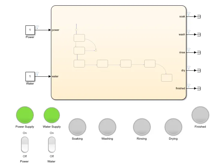
If the power supply is available, the system gets activated.
Providing the power supply, the system gets activated. then, water supply to the machine is checked.
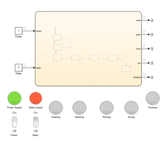
Case 2:
If the Water supply is not available, stop the process & indicate through LED.
Hence, water supply is necessary for washing process. it is checked before starting. if water supply is not available, the machine stops the process and indicates through a LED.
Case 3:
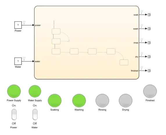
Soaking time should be 200s followed by Washing time of 100s.
Once the power and water supply are provided. the process starts by soaking the clothes for 200 seconds.
after soaking, washing starts and it is done for 100s.
Case 4:
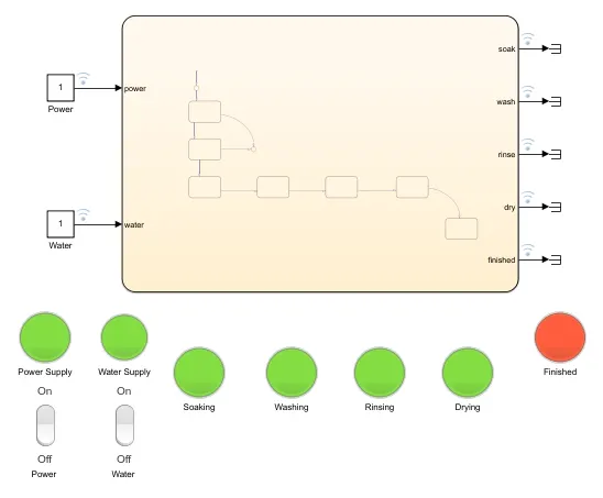
Then rinsing happens for next 20s & dryer runs for 50s and after all the processes have completed turn on the finished LED.
after washing, rinsing process happens for 20 seconds.
after that dryer runs for 50 seconds.
after all the processes are done in sequence, a LED indicates the completion.
Conclusion:
Thus, implementing a control logic for washing machine using State flow as per given sequence is done successfully.
GEAR SHIFTING:
AIM:
Make a Simulink chart for the “Gear shift” logic as per below conditions:
Speed Range (kmph) Gear
0 to 15 1
16 to 25 2
26 to 40 3
41 to 60 4
Above 61 5
Give speed input while the simulation is running & display the gear number.
Procedure:
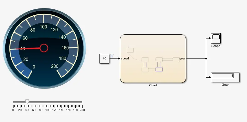
- A chart is created in Simulink for the gear shifting as shown below.
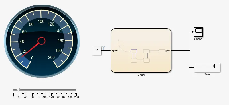
- A constant block is connected to the chart.
- A slider is connected to the constant to vary the input speed.
- Custom gauge block is connected to graphically show the varying speed.
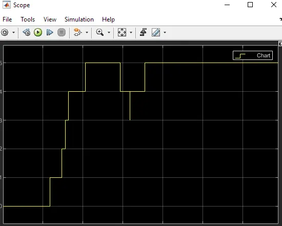
- A display and scope are connected to chart to show the gear number.
Simulink Model:
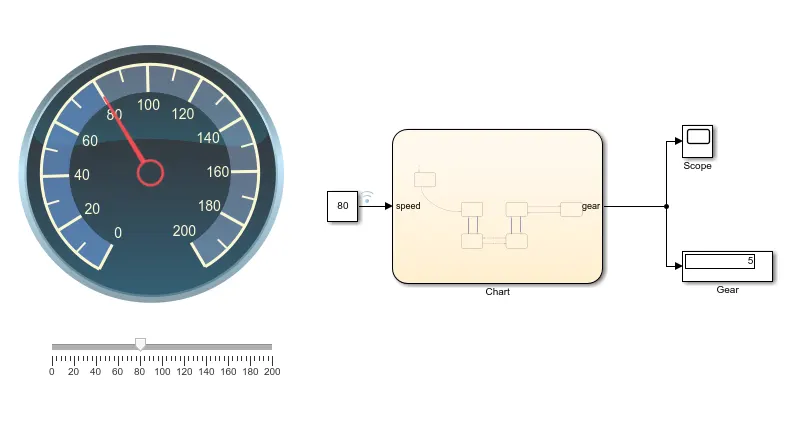
Chart:
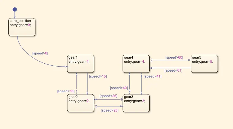
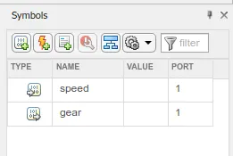
Required Speed Range (kmph) Gear
0 to 15 1
16 to 25 2
26 to 40 3
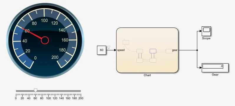
41 to 60 4
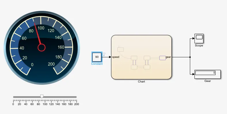
Above 61 5
In this model, for speed range from 0 to 15, gear shifts to 1st gear.
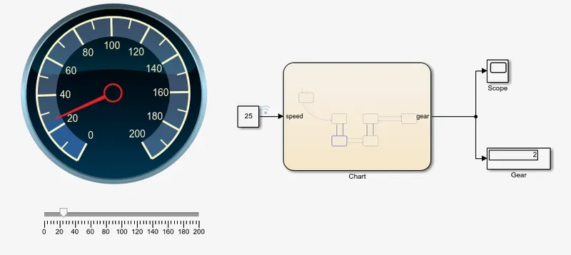
For speed range from 16 to 25, gear shifts to 2nd gear.
For speed range from 26 to 40, gear shifts to 3rd gear.
For speed range from 41 to 60, gear shifts to 4th gear.
For speed range above 61, gear shifts to 5th gear.
Scope:
Conclusion:
Thus, control logic for gear shifting using given speed range is done successfully.