Wiring harness design in CATIA V5 - 3D modeling Week 7 Challenge
REPORT_WIRING_HARNESS_FLATENNING
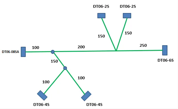
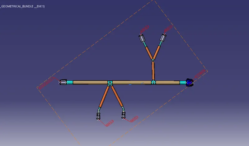
Aim: To Flatten previously made wire harness assembly using the CATIA Electrical Harness Flattening Workbench following the same layout provided and also to place the same in Drawing sheet.
Step_1:
Creating a new product file and enter the Electrical Harness Flattening Workbench. Save it in the same folder where the Harness product is saved.
Step_2:
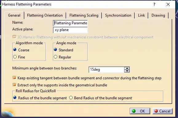
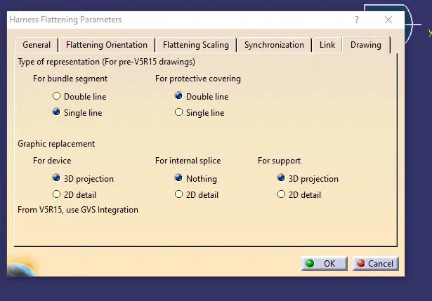
Define the Flattening parameters which is must required before proceeding Flattening. The parameters I used is shown in snip.
Step_3:
Use Extract option to copy paste our product file here, it is noticed that the original name is being saved with an extension of “_Ehf”.

Step_4:
Now click ‘Flatten’ option and select one Bundle, then in popup menu click ‘select all bundle’ to do the same, this option works only when my Bundle segment is fully connected, hence it should be ensured.
HARNESS FLATTENING:
- WE GO TO THE HARNESS FLATTENING WORKBENCH AND DEFINE THE FLATTENING PARAMETERS.
- WE USE THE EXTRACT COMMAND TO BRING THE HARNESS ASSEMBLY TO THE FLATTENING WORKBENCH HERE.
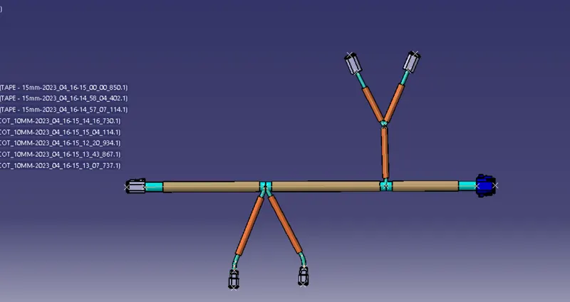
- CHOOSING A SUITABLE PLANE WE FLATTEN THE HARNESS ASSEMBLY.
- BUNDLE SEGMENTS ARE ROTATED AT THE REQUIRED ANGLES. THE HARNESS ASSEMBLY IS THEN DRAFTED.
- FLATTENING PARAMETERS ARE DEFINED IN ORDER TO MAKE THE BUNDLE AND THE CORRUGATED TUBES VISIBLE IN THE 3D DRAWINGS.
Step_5:
The required structure is made using Rotate and Roll command available in the same workbench.
Step_6:
Now use save management to save in proper folder, I.e in the same directory where my Bundle product file is saved to avoid instance of broken link.
Now for Drafting;
Step_7:
Create new Drawing file, save it in the same folder where Flattened file is saved.
Step_8:
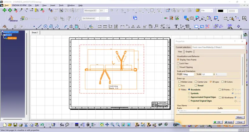
Click on front view option and select the required plane in the Flattened window, it is recommended to select any face on the connector which we used for annotation.
Step_9:
Every time if the main model is changed we need to rebuild the drawing file by checking ‘is always visible’ option available in ‘3D Wireframe’ tool by right click on the drawing layout and inside checking properties.
Step_10:
Finally add Annotations for naming connectors and telling umportant notes etc.., and save the all in same files.
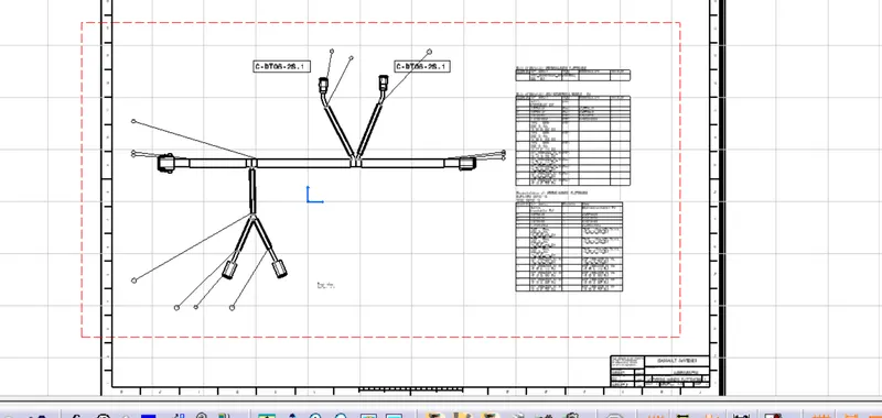
CONCLUSION: The Week 4 Challenge harness assembly is flattened as per given guidelines.
HENCE, THIS MEETS OUR MANUFACTURING REQUIREMENTS
NOTE:-
PLZ OPEN ALL THE FILES BEFORE OPENING THE ASSY. AS THERE IS SAVE MANAGEMENT IS NOT RESPONDING PROPER