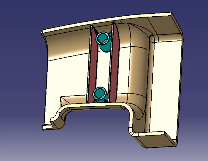
Week 9 - Attachment Feature Creation (Ribs & Screw Boss) - Challenge 1
AIM :-
Create the rib and screw bosses for the Drill Handle considering the design rules mentioned.
OBJECTIVES :-
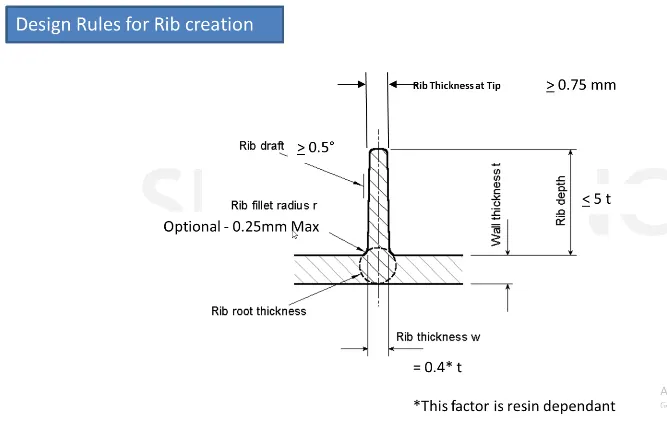
FOR RIBS
DESIGNING THE RIB & SCREW BOSSESS WITH THE CLASS_A SURCE PROVIDED.
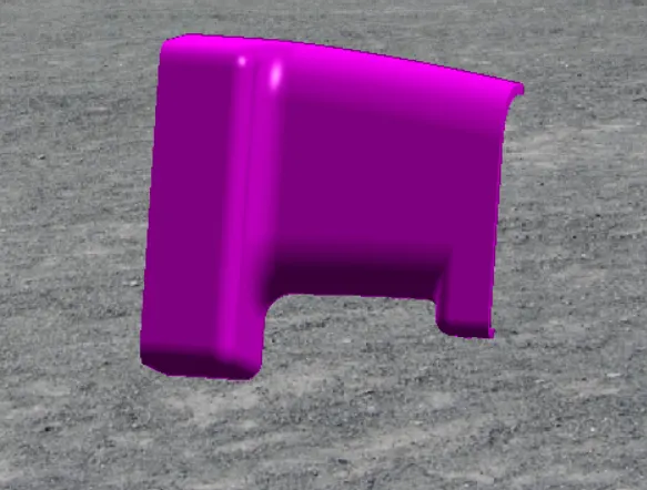
Create CLASS_B , CLASS_C AND CLOSED BODY WITH THE DRAFT ANALYSIS.
. 
FOR SCREW BOSSES :-
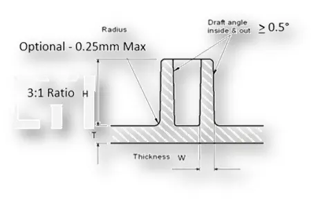
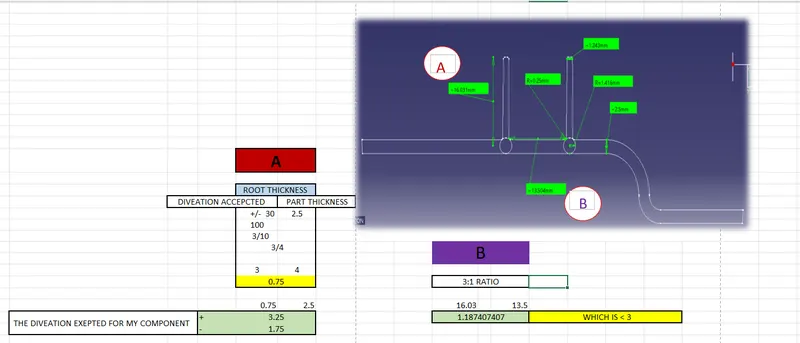
General Guidelines for Bosses:
- Draft - 0.5 degrees on the walls of boss
- Thickness - Typically 40%* of the nominal wall at the base.
- Height to Diameter Ratio - 3:1
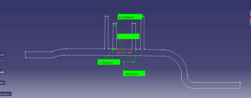
- Radii - 0.25mm maximum radii.
REPORT DESIGNING METHODOLOGY RIB AND SCREW BOSSES
USING CLASS_A SURFACE PROVIDED
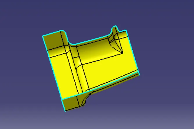
DRAFT ANALYSIS OF CLASS_A :-
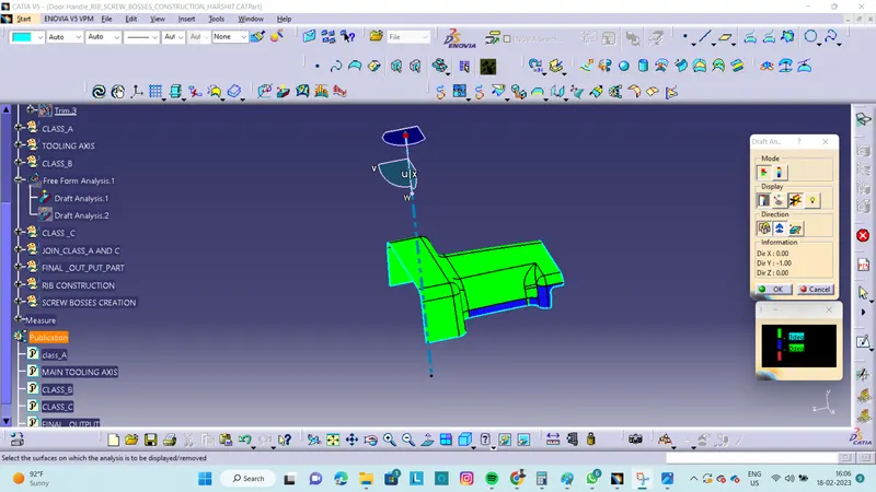
TOOLING AXIS :-
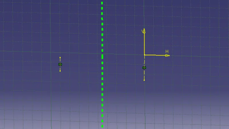
CLEARING XY
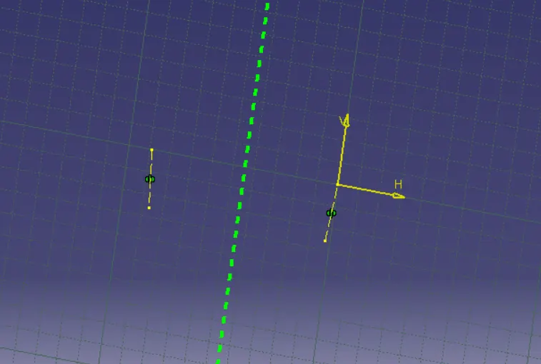
CLEARING YZ
MAIN TOOLING AXIS :-
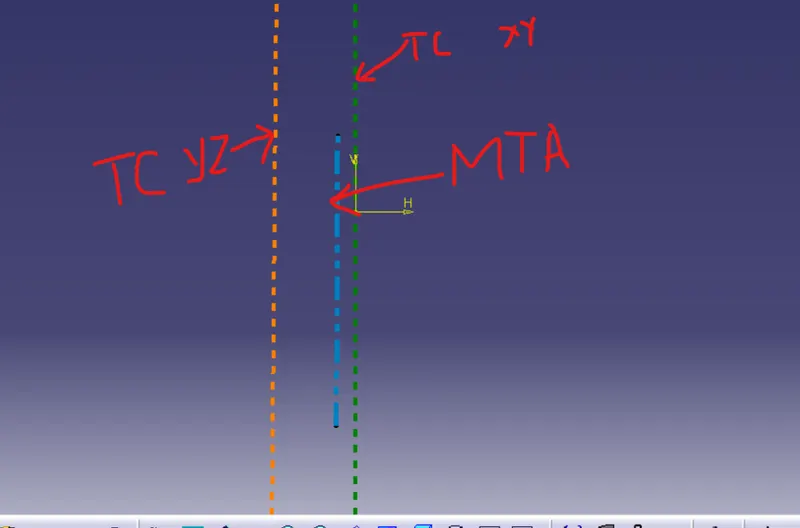
INTRODUCTION :-
RIB :-
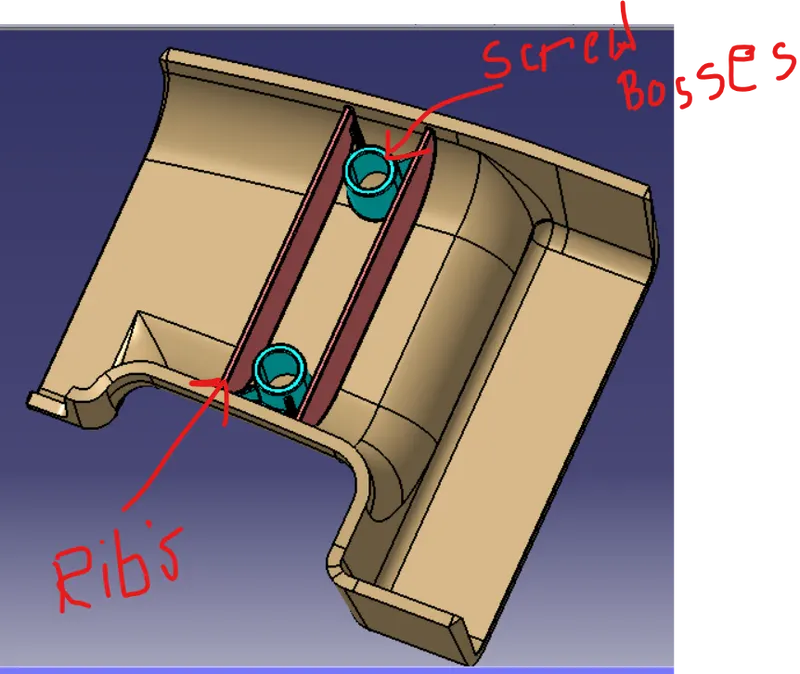
Ribs are a feature in plastic injection molded parts. They are thin extensions that run perpendicular from a wall or plane. They are commonly used to provide additional support and strength to a part. Thickness and location are essential to rib design.
IT ALSO ACT AS THE STOP OR GUIDE, PROVIDES ALIGNMENT IN MATING PARTS AND WORK AS THE LOCATOR TOO IN ASSEMBLY
SCREW BOSSE :-
Screw Bosses are Class B side engineering features which find use in many part designs as point for attachment and assembly. Most common variety consists of cylindrical projections with holes designed to receive screws, threaded inserts or other types of fastening hardware.
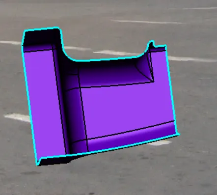
CLASS_B_CREATION:-
Class B: The Class B finish is a quality finish with only minimal imperfections. A Class B finish is the most common finish for exterior surfaces. It is normally specified on surfaces such as external covers, panels, and parts that are fairly prominent.
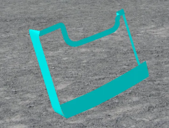
CLASS_C_CREATION :-
Class C: The Class C finish allows more imperfections than Class A or B. Class C is often specified for interior surfaces not readily visible, surfaces that will be covered by another part when assembled, or surfaces which the Customer feels do not need to mee a high cosmetic finish.
CLOCED_BODY_FINAL_OUTPUT :-
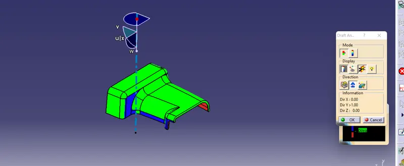
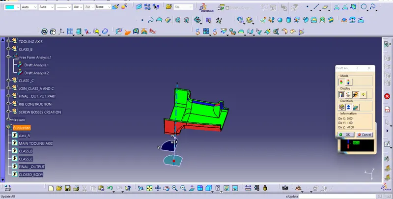
DRAFT_ANALYSIS :-
The Draft Analysis allows the user to easily analyze a part for proper draft angle. A Draft Angle describes the amount of taper for molded or cast parts perpendicular to the parting line.
REVERSE CONDITION :
DIFFERENT VIEWS :-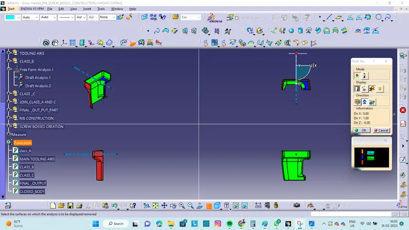
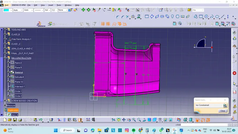
RIB CREATION :-
USING ABOVE CONSIDERATIONS :-
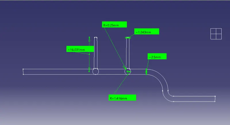
SCREW BOSS :-
FINAL OUT PUT PART :-