Fender Design
Objective
- To design a front fender from the given skin data and the master section provided with Drip mounting, A-pillar, Sill, Bumper and Baffle (splash) Mounts.
- To Prepare a report by explaining about Fender Design and its different mounts , manufacturing process and its design parameters.
What is a Fender ?
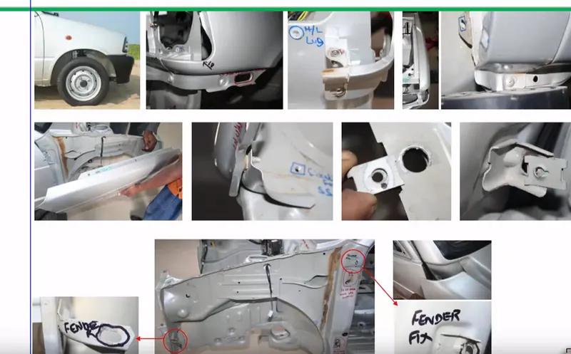
Fender is the term for the part of an vehicle body that frames a wheel well (the fender underside). Its primary purpose is to prevent sand, mud, rocks, liquids, and other road spray from being thrown into the air by the rotating tire. Fenders are typically rigid and can be damaged by contact with the road surface.Sticky materials, such as mud, may adhere to the smooth outer tire surface, while smooth loose objects, such as stones, can become temporarily embedded in the tread grooves as the tire rolls over the ground. These materials can be ejected from the surface of the tire at high velocity as the tire imparts kinetic energy to the attached objects. For a vehicle moving forward, the top of the tire is rotating upward and forward, and can throw objects into the air at other vehicles or pedestrians in front of the vehicle.
Importance of Fender:
- It is designed to provide resistance against wind, muds, and roadside particals.
- It is the sheet of metal covering of the car.
- Fender has a plastic part called Baffle or fender Liner which fits underside the fender to protect the metal from corrosion by stopping the flow of mud and water inside from different road conditions.
MANIFACUTRING PROCESS OF FENDER
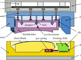
The manufacturing process includes the following steps that firstly, unfolding and shearing are carried out on a plate, wherein a proper cold roll specification is selected at first, a cold roll is unfolded, and then the unfolded cold roll is sheared to an iron plate of the corresponding size according to production material specifications; secondly, oil pressing and punching are carried out, wherein the iron plate is extended at first, then side shearing and punching are conducted on the iron plate, folding and shaping are carried out on the iron plate, and finally reshaping is carried out on the iron plate; thirdly, small first parts of the fender are machined, wherein first of all, the iron plate is punched to a needed outer contour blank, then the iron plate completing the outer contour blank is further shaped, and the iron plate is punched at last; fourthly, installation and welding of a metal plate are conducted. The manufacturing process for the car fender is simple and high in production efficiency; a body of the fender and the small parts can be separately machined, so waiting time is shortened; working efficiency of production is improved.
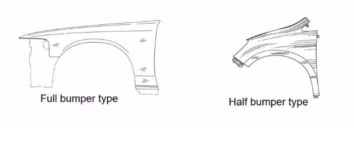
There are 2 types of fenders.
- Full Bumper Type
- Half Bumper Type
Full Bumper Type: Full Bumper Type is not used now a days because it requires large size of balnk to produce the part and it occupies more space.
Half Bumper Type: Half Bumper Type Half bumper is used because the waste of material is less & can produce two fender at the same time by slightly increase the raw sheet. and to reduce the weight & cost mostly bumper fender are been produced.
Data given to design :-
- The drip area should be made after leaving the space of 150mm from front for headlight mounting and before 200mm from cowl area and 10mm distance left from Engine room.
- The radius values of Drip area at dfferent stages
- The angle from top of flange is 40 degree and 8mm long is created to stop the view of Engine Compartment.
DIFFERENT MOUNTING AREA :-
Mountings:
- Drip Mounting Area
- Sill Mounting Area
- A-Pillar Mounting Area
- Bumper Mounting Area
- Baffle or Linear Mounting Area
- Drip Mounting Area
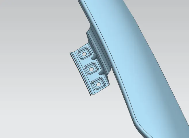
- The drip area would be recognizable fom the opening between Hood and Fender.
- This mounting is attached to the engine compartment of the car.
- A min 150mm distance is kept from the front side and a distance 300mm or less can be kept on the rear side .
- This is to avoid the springback during the manufacturing . the edge of the mounting should atleast 10mm away from any nearby component in the engine.
- The drip area should be less than 40mm.
- The embosess that are created on the drip mounting should be flat with respect to the curvature.
- A dart is provided at the edge of the drip mounting to increase the stiffness.
2. Sill Mounting Area
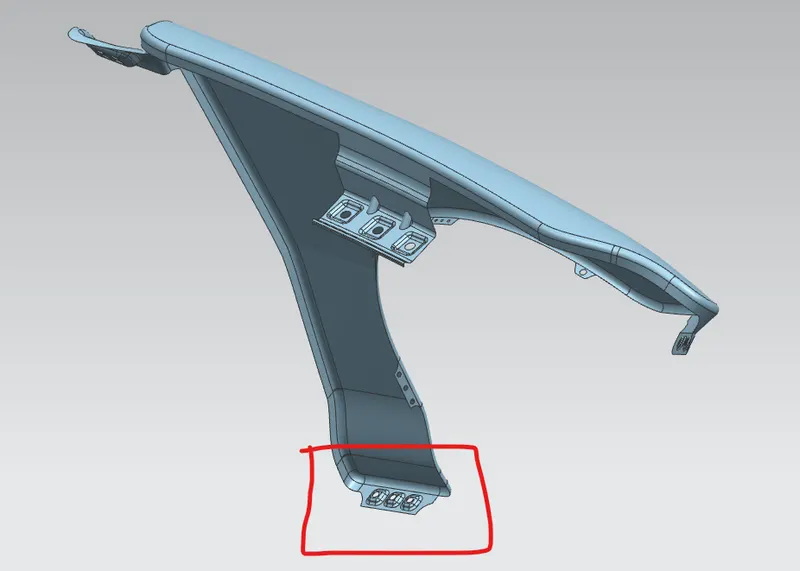
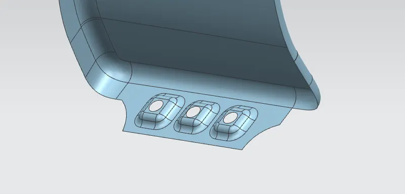
- This is palced basically at the botom of the fender. The mounting part is created such that it firmly fits to the sill.
- The embosess that are created on the drip mounting should be flat with respect to the curvature.
3. A-Pillar Mounting Area
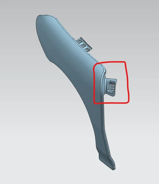
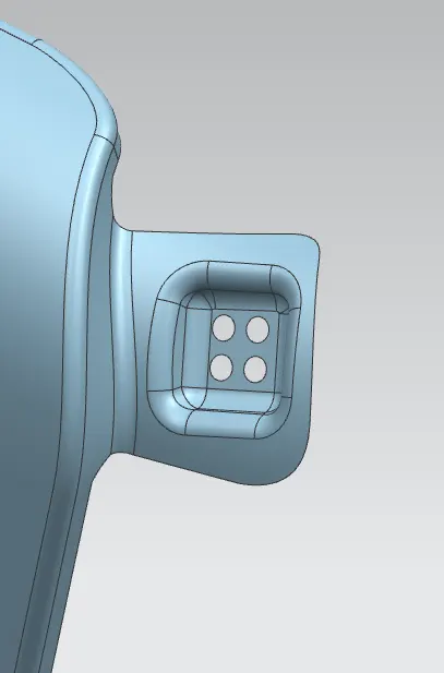
- A-pillar mounting is a vertical support on a vehicle. It holds the windshield set up and just downside to the A-pillar fender is mounted to hold the position.
4. Bumper Mounting Area
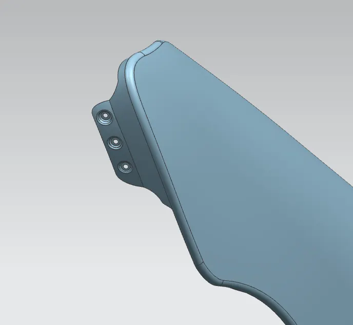
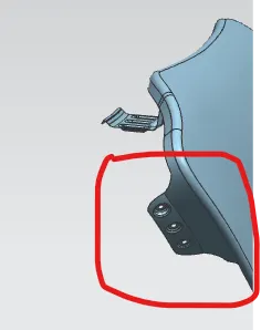
- Since Bumpers are mounted over the fender it is called Bumper Mounting Area.
- It is placed at the front side of the fender,the bumper mount area of fender, mounts on the chassis to hold the position.
5. Baffle or Linear Mounting Area
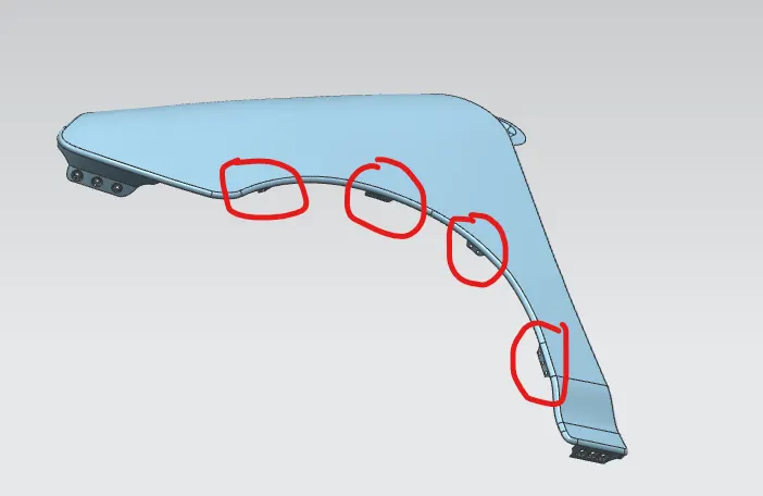
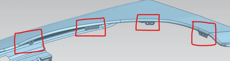
- A plastic unit is placed which is called baffle/splash fender linear mounting is placed.
- These mountings are created for fixing the baffle/splash mounting.
- Usually a baffle is mounted on the fender of the car . It is mounted on the wheel arch area .
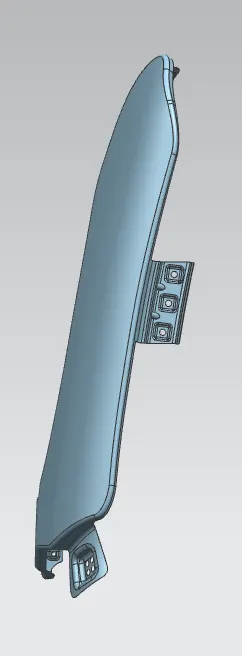
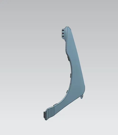
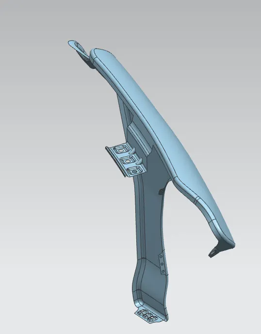
DIFFERENT VIEW'S of a Fender:
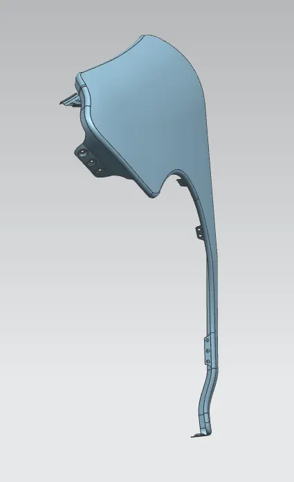
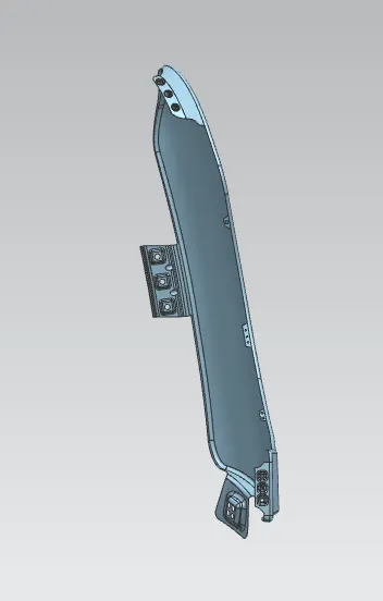
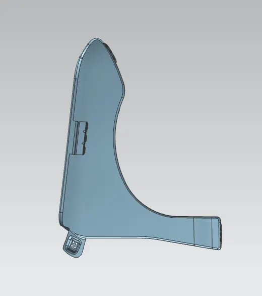
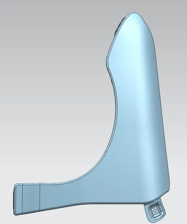
Conclusion:
We designed the Front Fender in NX application with proper mountings by using the Master Sketch and Design Parameters.