Wiring harness design in CATIA V5 - 3D modeling Week 2 Challenge
WIRING HARNESS DESIGN IN CATIA V5
INTRODUCTION:
A wire harness is a system of insulated conducting wires bound together with insulating materials, used in the electrical system of a motor vehicle, complex machine or aircraft. Wire harness engineering is the development process of an electrical foundation for the safe and reliable distribution of power throughout a system. It forms the foundation of reliable, cost-effective and successful product design and manufacturing.
The purpose of a wire harness is to organize individual wires into a single unit to efficiently transmit electrical power and signals. A wire harness reduces labor time and potential for human error, enabling technicians to fit complex wiring assemblies into small or hard-to-reach spaces.
For example, in some modern vehicles there are approximately 40 different harnesses, comprised of roughly 700 connectors and more than 3000 wires. The bundling of wires and cables into a wire harness simplifies connection to larger components as a single unit for drop-in installation, instead of connecting every individual strand.
Wire harness design is the process by which an engineer evaluates the requirements of an electrical part of system, given available physical space to create an assembly of wires to deliver power and information as needed. The design must connect all necessary components and not interfere with other systems critical to the operation and purpose of the product.
For example, a wire harness in a car must power everything from drive controls to passenger comforts and safety The wire harness design must consider and account for mechanical systems, passenger, weight distribution, plumbing and more to ensure safe and efficient drive.
Some important terminologies used in Wiring harness design:
BASICS OF ELECTRICAL DISTRIBUTION SYSTEM (EDS) AND WIRING HARNESS
1) Electrical Distribution System: It runs from front end to rear end of the vehicle. It involves physical and logical architecture schematic development, power distribution, wiring harness design, wiring harness component design of given electrical system. It ensures the physical location of all electrical components placed in the vehicle. It provides the logical connectivity between electrical components. It has electrical controller unit for different sections like Airbag ECU, ABS ECU, Engine (ECU).
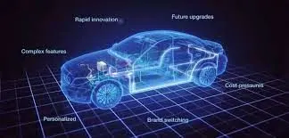
2) E&E Architecture:
It is the high-level logical connectivity diagram. It represents all the systems, sub-systems and logical connections between them. It shows the Control Area Network (CAN) between different electronic components.
3) Logical schematics:
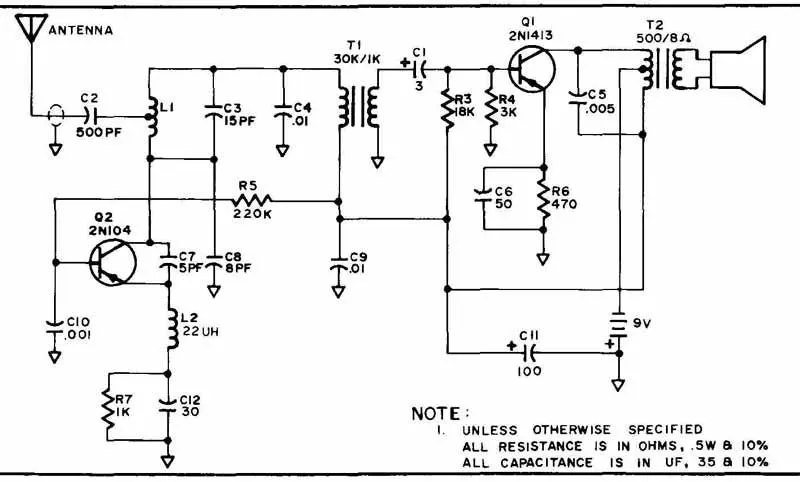
Detailed design of E&E architecture. It shows the logical connectivity between different components and controls of given systema and subsystem. It does not define any other parameter except electrical connectivity.
4) Electrical schematics:
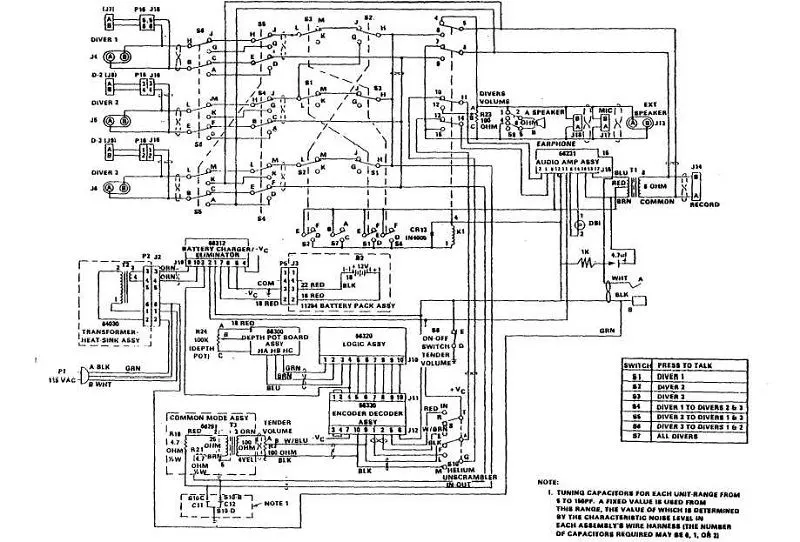
Detailed design of logical schematics, pin to pin connectivity, properties, fusing distribution, grounding distribution, interconnects, wire properties (wire gauge, color, type), circuit properties (circuit number, connector designation number, control device number), specification of components, end results of electrical core design of system and primary input for harness design.
5) Wiring harness topology:
Strategy to split the harness between different pieces to achieve the best manufacturability, serviceability and cost-effective design.

6) Wiring harness routing:
It provides the desired path of wiring harness into given vehicle environment by applying set of design rules and industry best practices.
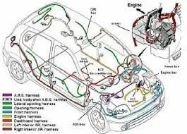
7) Wiring harness packaging:
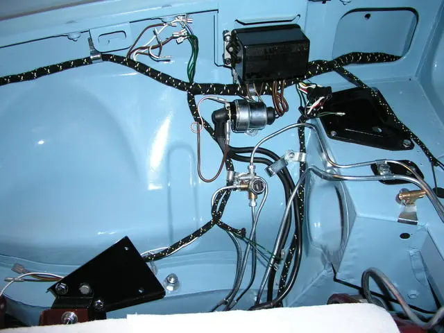
Fixing/mounting strategy of wiring harness routing to ensure the safe, reliable and durability of wiring harness by applying set of design rules and industry best practices.
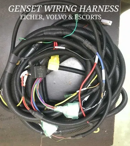
WIRING HARNESS ASSEMBLY
The term Wiring Harness refers to the assembly of
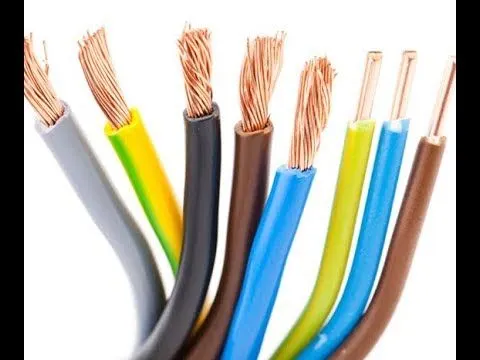
1) Wires:
Various bundled wires together. Each individual wire is responsible for carrying the electrical signals and energy. Wires are made up of Cu conductors insulated with PVC insulation.
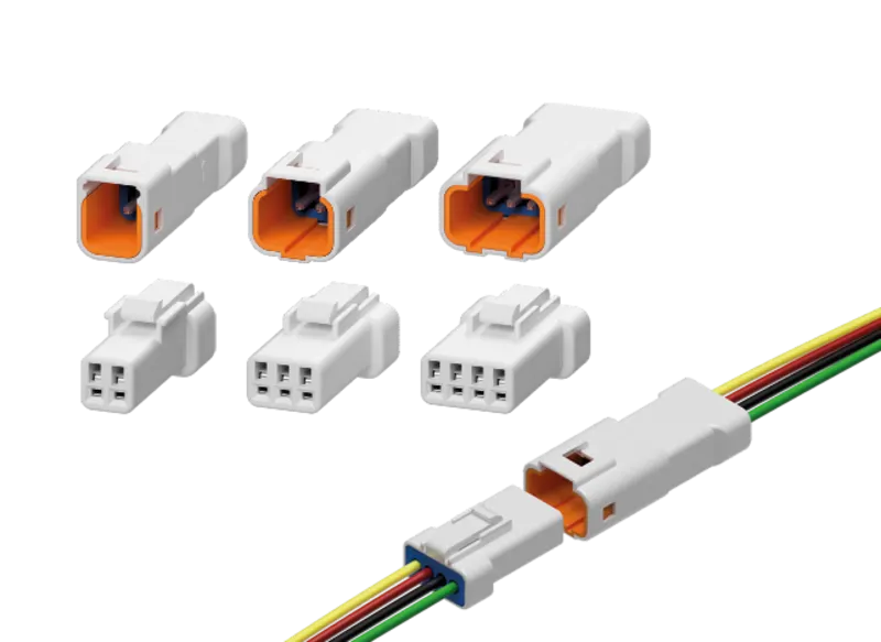
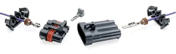
2) Connectors:
These are electro-mechanical device used to join electrical termination. Connectors create an electrical circuit. These are plastic molded housing with locking and retention feature.
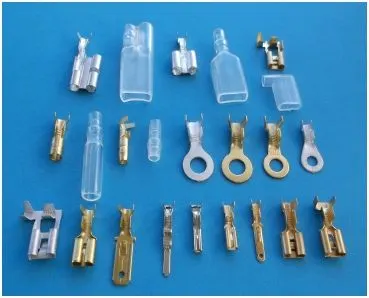
3) Terminals:
A device used to terminate a conductor that is to be affixed to post, stud, chassis, another tongue etc., to establish electrical connection. These are metal conductors with plating constructed in specific shape.;
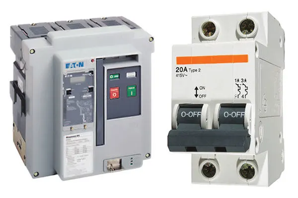
4) Protection devices:
Corrugated flexible tube.
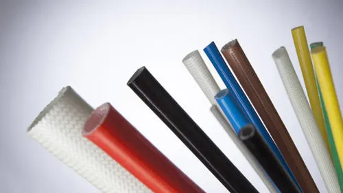
5) Insulation:
adhesive and non-adhesive tapes and sleeves. Polymer or cotton/polymer (very effective in high-temperature zone).
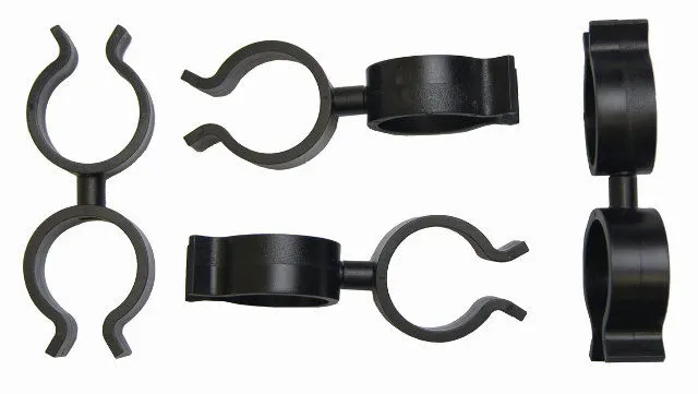
6) Clips & Clamps:
Plastic molded parts with mounting /snapping features.
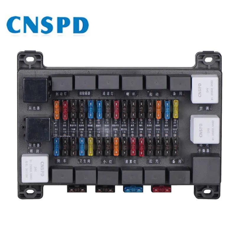
7) Fuse and relay box:
Plastic molded parts used to package fuses and relays in systematic manner.
8) Retention device:
Plastic molded parts to mount connector and other harness components. Connector backshells.
9) Guiding channels:
Plastic molded parts or metal parts designed to guide harness bundle in given geometric area to secure and protect the harness.
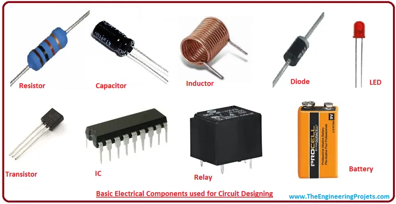
10) Electronic components: Diodes, terminating resistors, flasher, Timer circuits are some parts of harness supply.
DESIGN OF WIRING HARNESS IN CATIA V5
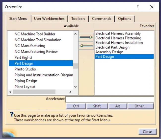
To design the wiring harness in CATIA V5, the interface and some settings have to be changed in the design modeler.
The electrical part design, electrical harness assembly, electrical harness installation, electrical harness flattening, and electrical assembly design have to be customized to the workbench for easy access.
1) Electrical part design: The mechanical part is converted into an electrical part by manipulating the electrical properties into it.
2) Electrical Harness Installation: Route the harness.
3) Electrical Harness Flattening: Finalizing the routing
CATALOGUE

CUSTOMIZED SETTINGS FOR ELECTRICAL ENVIRONMENT
An electrical catalog has to be made to save the electrical parts into it and use it whenever required.
1)Infrastructure settings: In the product structure option enable cache management.
2) Equipment and system: In Electrical mapping select the connector catalog which is created as an electrical catalog.
3) Electrical Harness installation
DESIGN OF WIRING HARNESS IN CATIA V5:
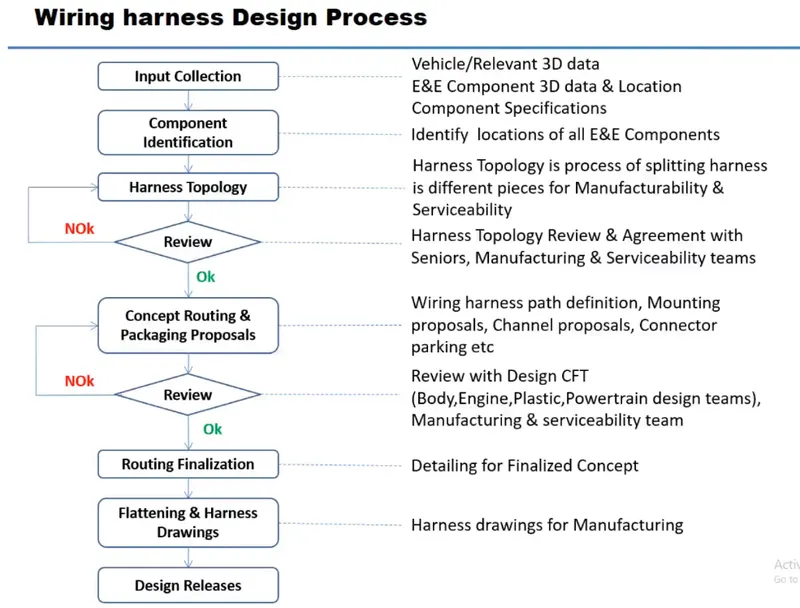
Schematic Diagram for Wiring Harness Design Process:
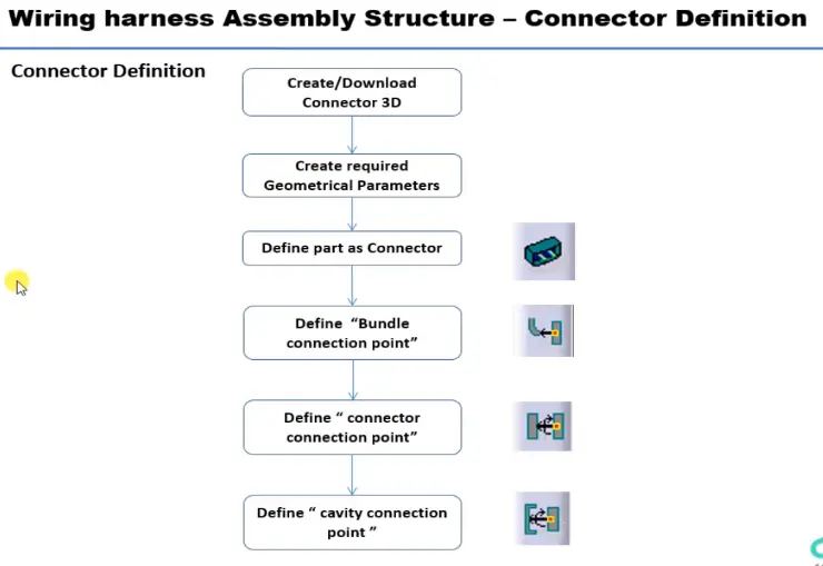
Schematic Diagram for Connector definition Process:
Some more important terminologies with respect to connectors
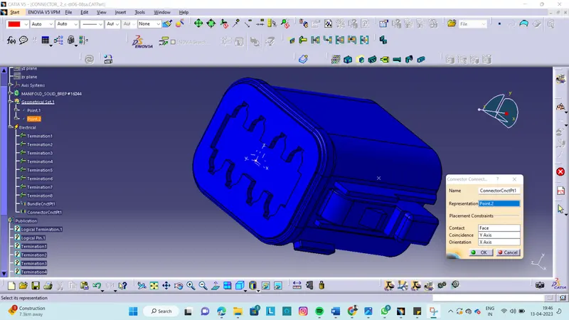
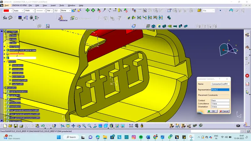
1) CONNECTOR CONNECTION POINT: A connector connection point is used to specify how mating connectors are placed when making an electrical connection. We have to Open any document containing a single insert connector where we want to place a connector connection point. Then, we will place a Contact constraint. for example, a surface or a point.
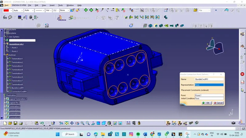
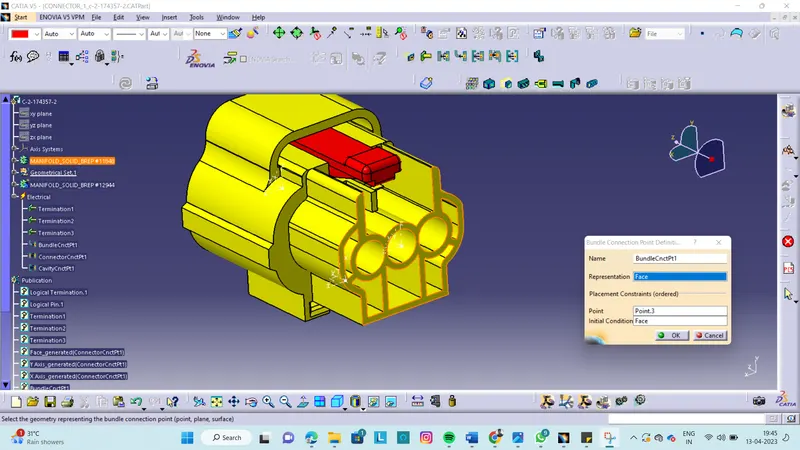
2) BUNDLE CONNECTION POINT: To implement the transition of connections or cable connections from multi- to single-line representation, and vice-versa, so-called bundle connection points are used.
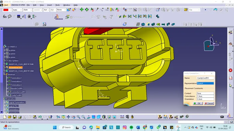
3) CAVITY CONNECTION POINT: A cavity connection point is used to specify how a device is placed in a cavity when making an electrical connection.
We have to define following component as Electrical Connector using Electrical Part design Workbench and also Define all the necessary properties to Connectors & Clip.
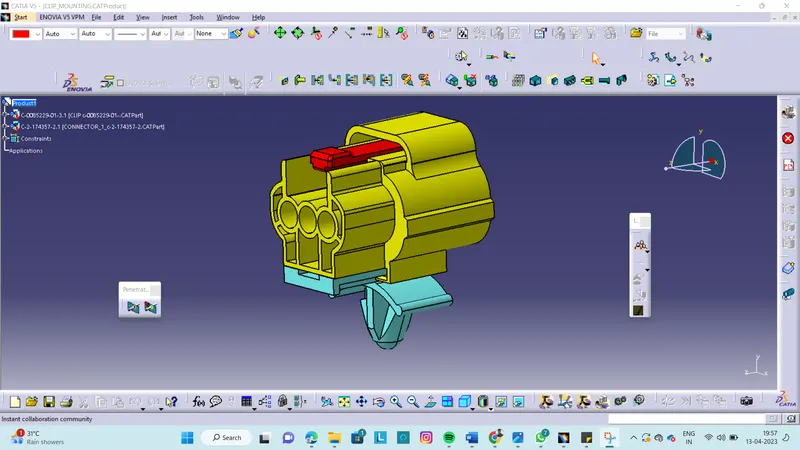
Deutsch DT06 : Connector
Tyco 174357-2 :Housing for Female Terminals
Tyco 85229-1 : Mounting Clip
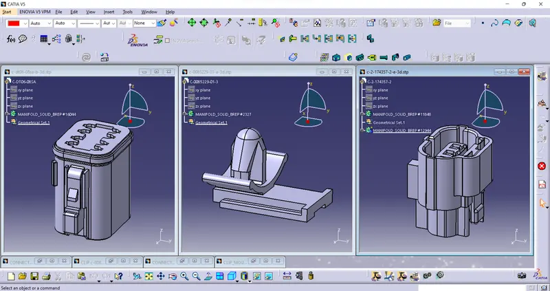
1) CREATING POINT &AXIS SYSTEM
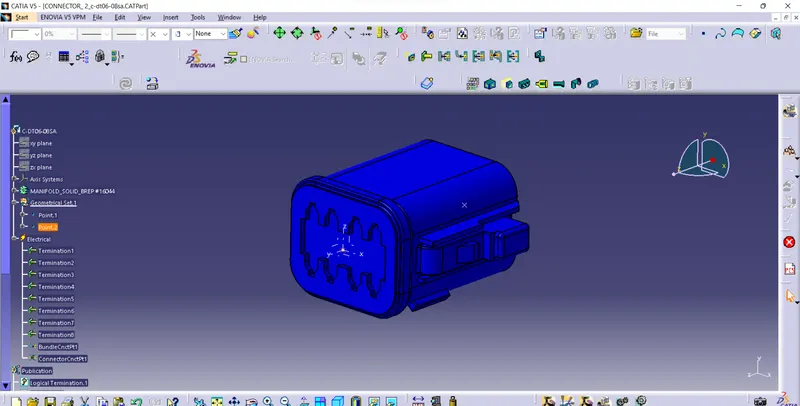
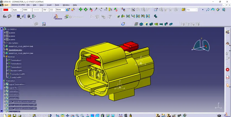
2)ENSURING THAT THE
Y FACING TOWORDS THE MATING/CONNECTING FACE TOWORDS THE CONNECTOR FACE.
X - TOWODS THE LOCKING MECHANISM OR THE BACK SHELLES
Z - TOWORDS THE TOP DIRECTION
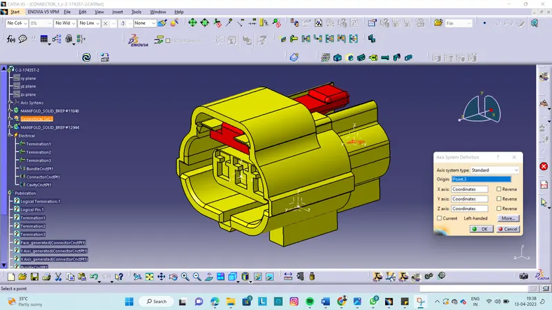
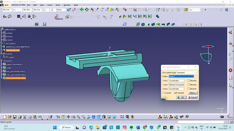
3) SHIFT TOWORDS THE ELECTRICALPART WORK BENCHDEFINE THE PART AS THE CONNECTOR
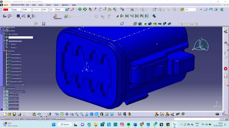
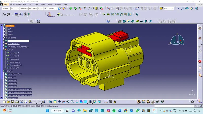
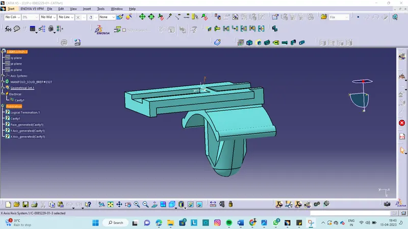
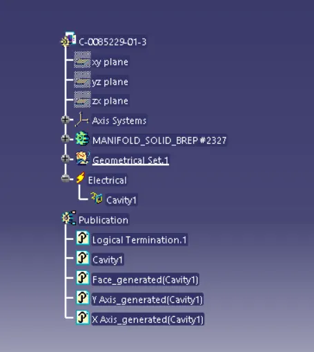
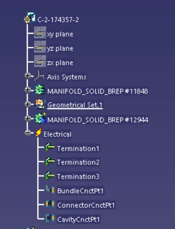
4) THEN DEFINE THE BUNDLE CONNECTION POINT
for initial condition select the same perpendicular/normal entry to the connector face
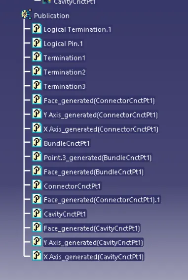
5) DEFINE THE CONNECTION CONNECTOR POINT
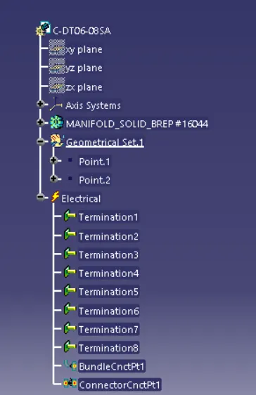
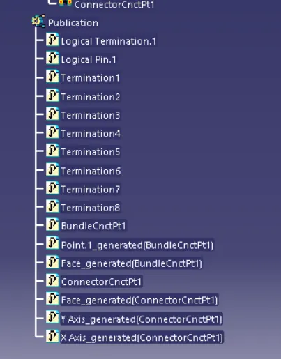
6) LASTLY DEFINE THE CAVITY CONNECTION POINT
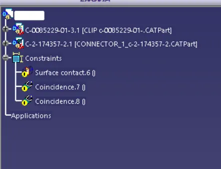
ASSEMBLY OF CLIOP AND CONNECTOR IN ELECTRICAL ASSEMBLY DESIGNWORKBENCH