Roof Design
DESIGNING THE ROOF USING NX-CAD
OBJECTIVE
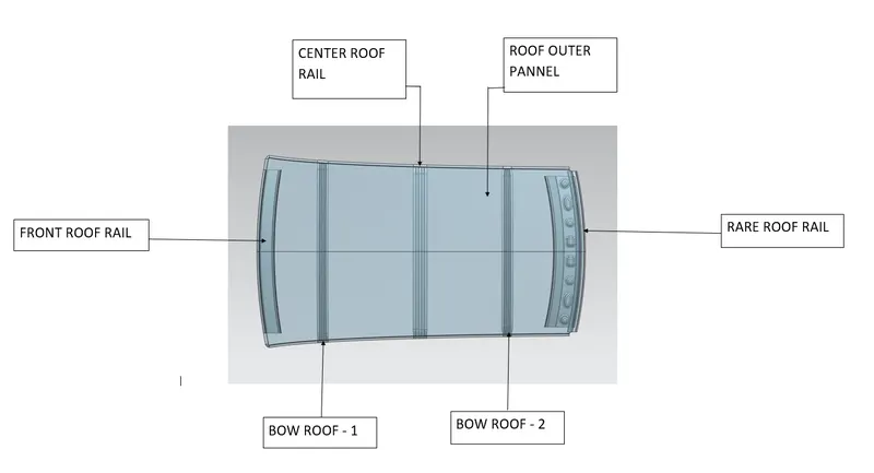
To Design the required reinforcment and flanges for the given Class A surface of Roof.Required reinforcments are
- Front Roof Rail,
- Rear Roof Rail,
- Bow Roof 1,
- Bow Roof 2.
After designing the roof assembly completely we need to perform the Heat distortion analysis and the Snow Load Analysis, Perform the draft analysis for each reinforcements and Finding moment of inertia and section modulus for
Bow roofs , central roof rail , front roof rail and rear roof rail .
What is a car's roof called?
An automobile roof or car top is the portion of an automobile that sits above the passenger compartment, protecting the vehicle occupants from sun, wind, rain, and other external elements. The roof is not a single panel as seen from the exterior it consists of front roof rail, bow roofs, center roof rail, and rear roof rail with different thicknesses which act as a reinforcement for the top.
INTRODUCTION :
Design of any product starts from an requirement .The design engineer sketches the product based on the the requirement .Then the 2D sketch with the proper dimensions is converted into the 3D model using the advanced CAD software's .The another important thing in the design is that ,every product
what are the main Design and Functional Requirements for the Roof ? :-
While designing of roof following considerations have to be taken into account.
- Head room clearance.
- Curvature Study.
- Visibility Criteria.
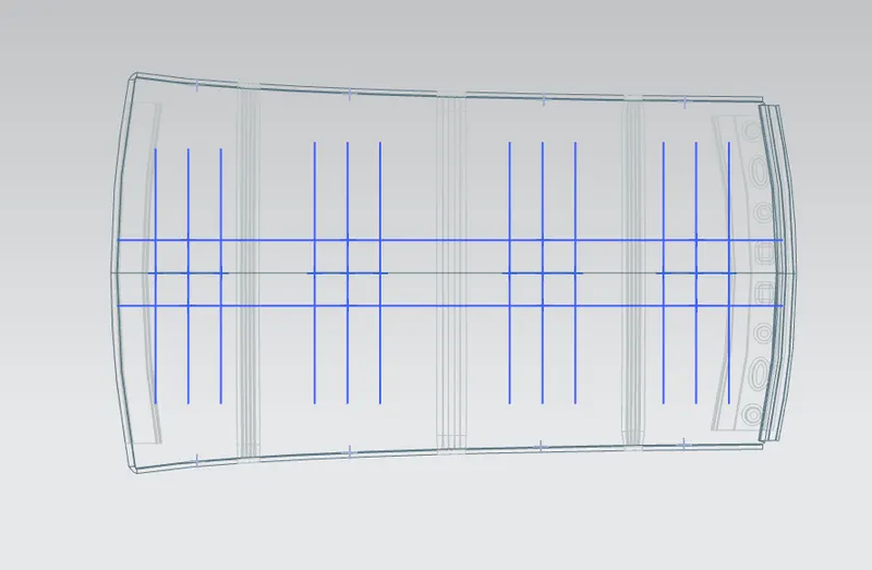
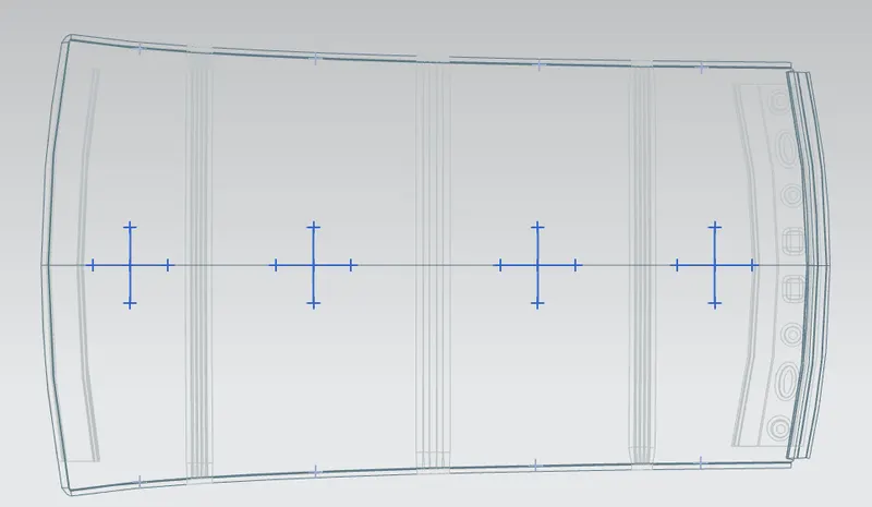
- Heat Distortion and snow load criteria
Design Considerations are :-
- Clearance of 5 mm should be present between outer roof rail and Front roof rail, Rear roof rail, Bow roof, and Reinforcement center where mastics are used for adhesion.
- Thickness for all sheet metal parts - 0.75 mm.
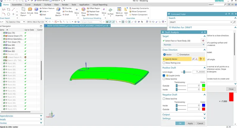
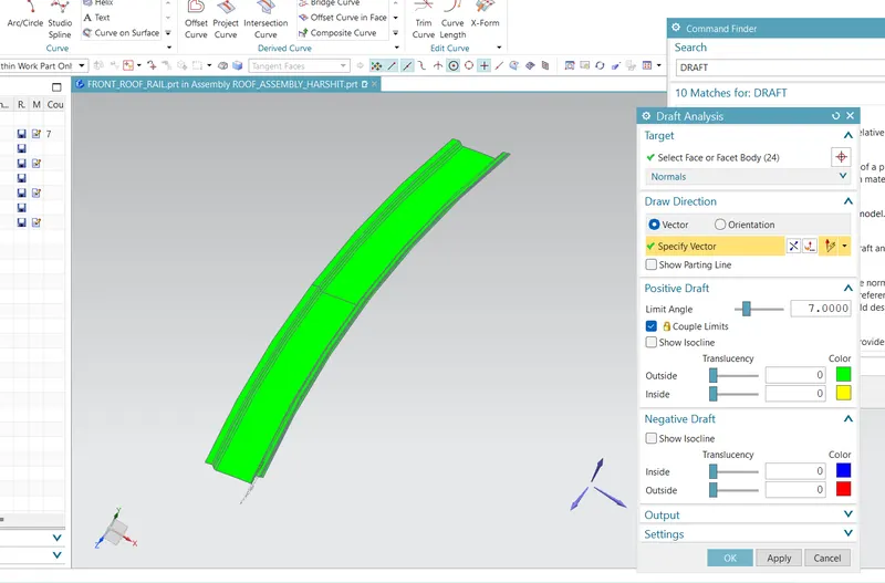
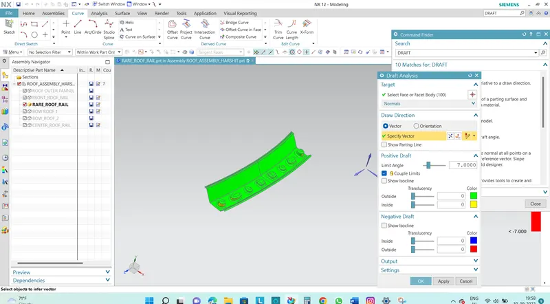
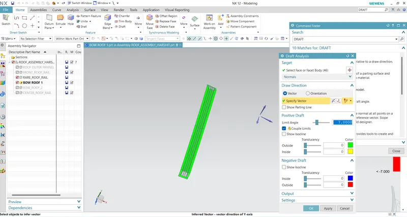
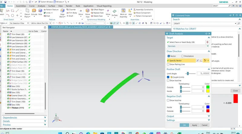
- A minimum draft of 7 degrees is required for all the faces.
- All edges should have fillets and there should not be any sharp edges present.
DESIGNING OF ROOF STARTS WITH : -
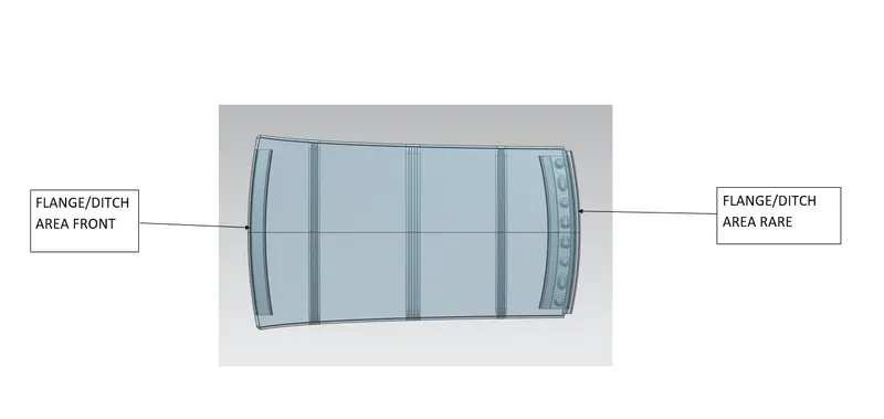
- Ditch Area:
The ditch area is the extended portion of the main roof which is concealed by the other BIW components followed by the other aesthetic surface. It also serves the joining purpose for the reinforcement which is joined using the spot welding. Visibility, Clearance for windshield and back door mountings are some of the factors needed to be considered while designing the ditch area.
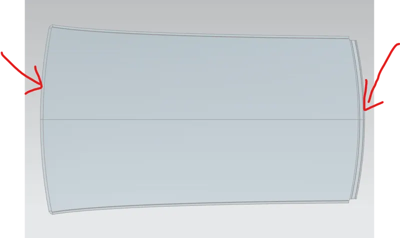
FRONT ROOF RAIL:
The front roof rail is created at the front side of the roof to provide strength to the roof. Headroom clearance and the driver visibility are the two important factors to be considered while designing the front roof rail. the front roof rail is connected to the roof outer panel with the help of mastic seal.
GIVEN MASTER SECTION --> 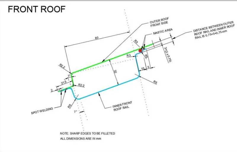
MODELED COMPONENT (THICKENED) --> 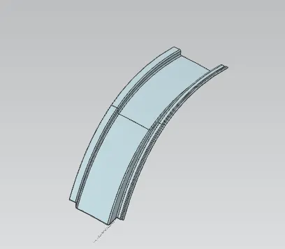
RARE ROOF RAIL :
It is a reinforcement provided to the rear portion of the roof and it also features the tailgate mountings. The development of RRR is dependent upon the rear headroom clearance and rear visibility criteria. The minimum clearance from the headliner to the roof is should be 80mm which will vary from variant and region to region.
GIVEN MASTER SECTION --> 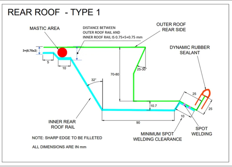
MODELED COMPONENT (THICKENED) --> 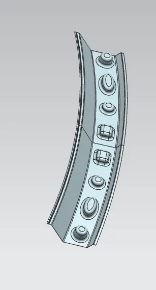
BOW ROOF RAIL 1 & 2 :
A Roof Bow is a sheet metal part, usually spot welded to the BIW inner frame, forming the inner structure of the vehicle body
- Mastics are applied between roof and the roof rail and bow roof.When the mastic gooses out it joins the roof rail and bow roof with the Roof.
- If the roof was small with better curvature we need to use only one reinforcement (center) that wiil act as bow roof.
- No.of bow roof increases if the car size becomes longer and taller.If flat region increases bow roofs also increases.
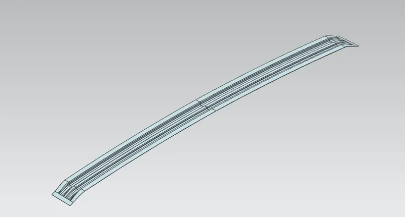
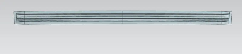
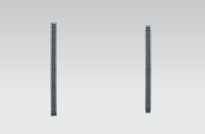
MASTIC POINT PLACE :
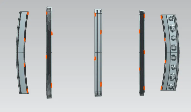
MASTIC POINT
PLACE TO SPOT WELDING :
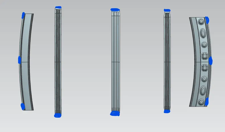
SPOT WELDING
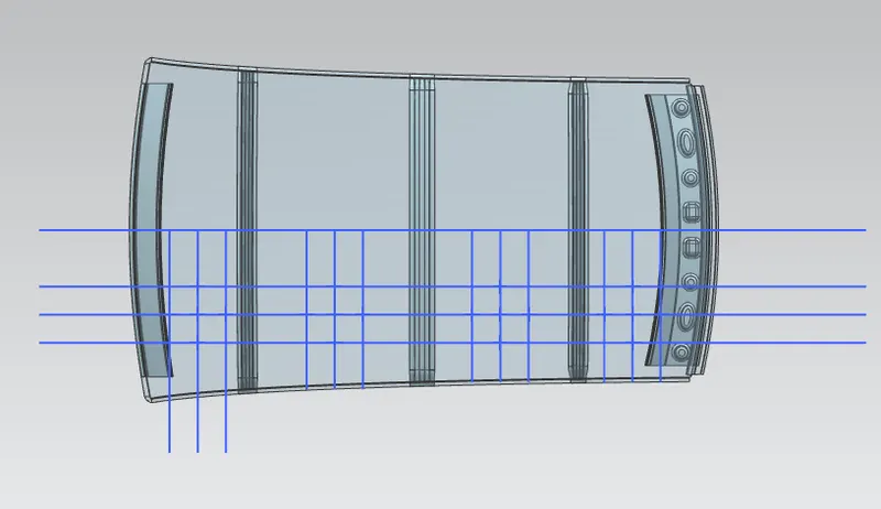
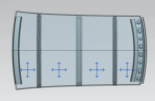
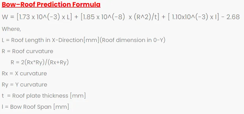
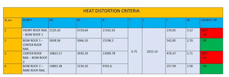
HEAT DISTORTION CRITERIA :
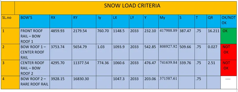
SECTION MODULUS :
It is a geometric property for a given cross-sect ion used in the design of beams or flexural members. Other geometric properties used in design include area for tension and shear, radius of gyrat ion for compression, and moment of inertia and polar moment of inertia for stiffness. Any relationship between these properties is highly dependent on the shape in question.Equations for the section moduliof common shapes are given below.
The elastic section modulus is defined as,
s= 1/ y
where :
S= Section modulus
I = second moment of inertia (or area moment of inertia,not to be conf used with moment of inertia)
y = Distance between the neutral axis and the extreme end of the object (mm)
BOW ROOF 1:
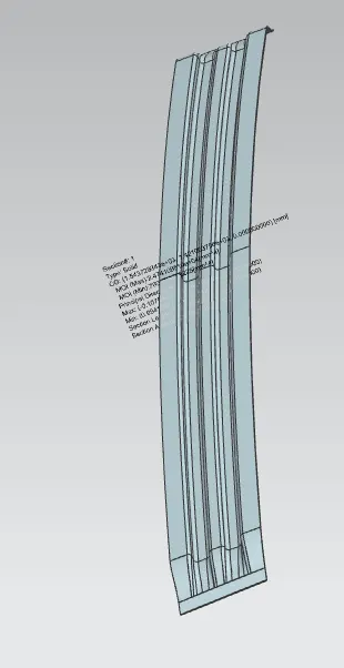
MOI (Max) : 2.474109519
MOI (Min) : 760.704018225
S = I/Y
Y = 1155/2 = 577.5
S = 760.7/577.5 = 1.2999 mm^3
CENTER ROOF RAIL :
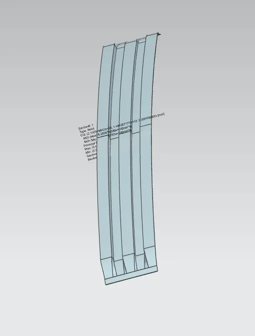
MOI (Max) : 5.389614236
MOI (Min) : 1.036119753
S = I/Y
Y = 1084 /2 = 542
S= 1.0361/542 = 0.0019mm^3
BOW ROOF RAIL 2 :
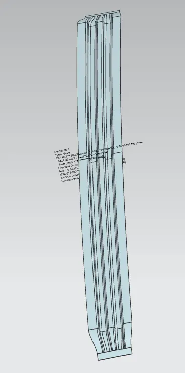
MOI (Max) : 2.474367382
MOI (Min) : 774.360053670
S = I/Y
Y = 1092/2 = 546
S= 774.36/546 = 1.418241 mm^3
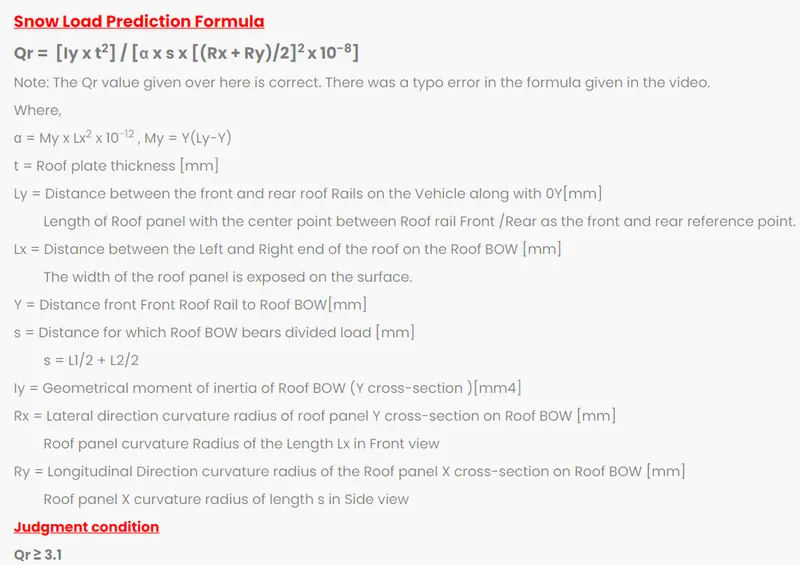
SNOW LOAD CRITERIA :
DRAFT ANALYSES
In NX to check whether the sheet metal part we have designed can be deep drawn, there is an option called draft analysis. This type of analysis is performed based on color ranges identifying zones on the analyzed element where the deviation from the draft direction at any point, corresponds to specified values.
ROOF OUTER PANNEL :
FRONT ROOF RAIL :
RARE ROOF RAIL :
BOW ROOF :
CENTER ROOF RAIL :
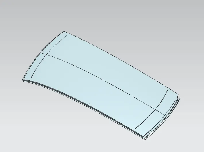
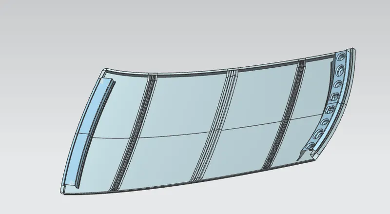
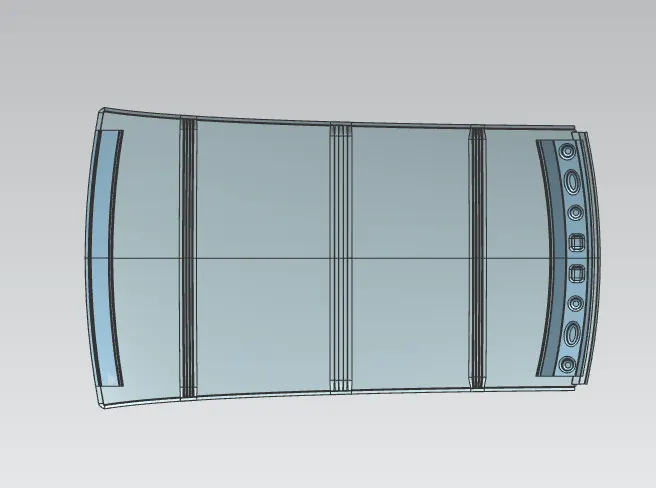
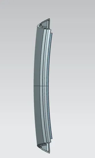
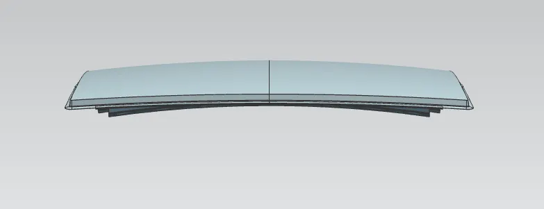
FAINAL VIEW OF ROOF :

CONCLUSION :
Thus the roof is designed with all the necessary reinforcements and roof rails according to the given master section and the styling surface, by considering all the design parameters. Also, the curvature study is done by taking the heat distortion and snow load criteria for determining the strength of the roof.