Week 9 - Attachment Feature Creation (Ribs & Screw Boss) - Challenge 1
Attachment Feature Creation (Ribs & Screw Boss)
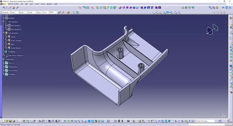
Objective:
Create the rib for the Drill Handle considering the design rules mentioned.
Given Data:
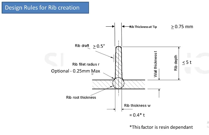
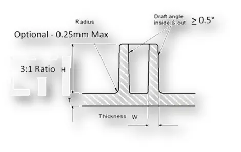
General Guidelines for Bosses:
- Draft - 0.5 degrees on the walls of boss
- Thickness - Typically 40%* of the nominal wall at the base.
- Height to Diameter Ratio - 3:1
- Radii - 0.25mm maximum radii.
Creation of Tooling Axis:
Making an intersection on the x-y plane.
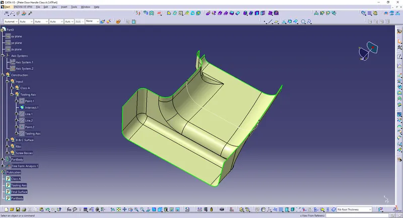
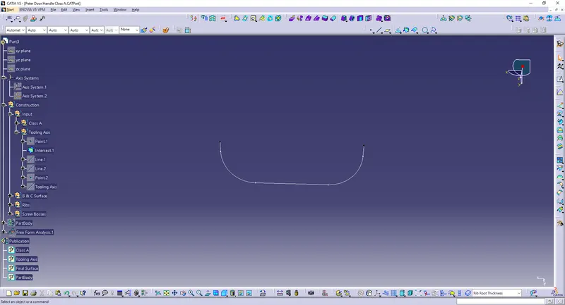
Make 2 lines.
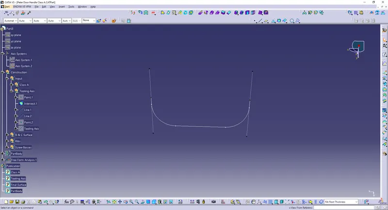
Create a bisecting line to get the Tooling Axis.
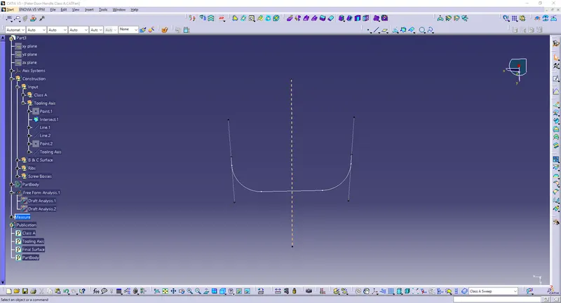
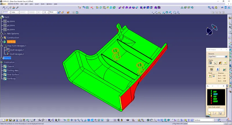
Checking the tooling axis by draft analysis.
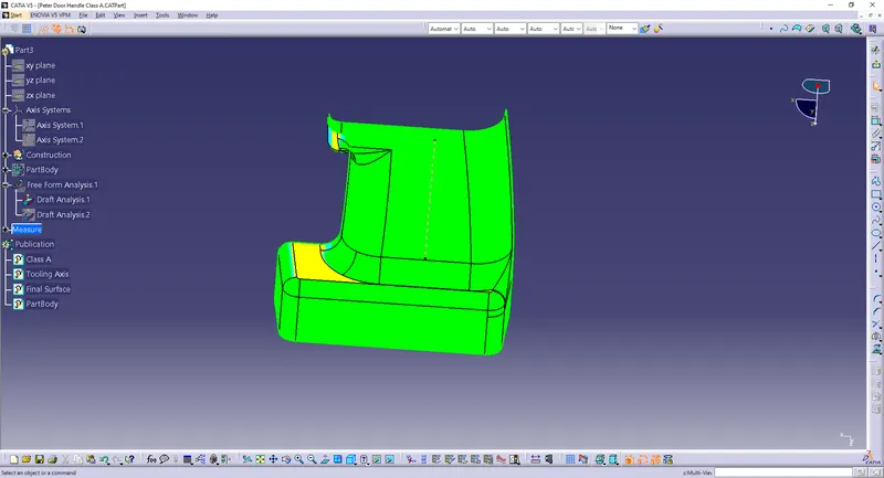
Part Design:
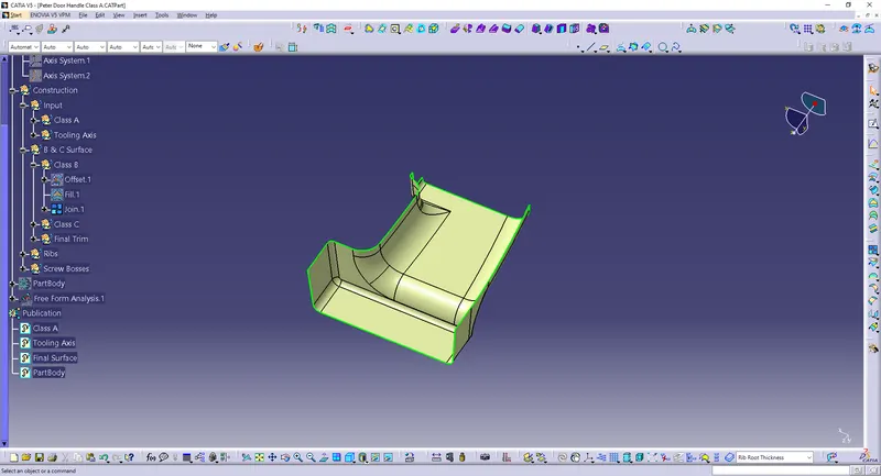
The B surface is created by an offset value of 2.5 mm:
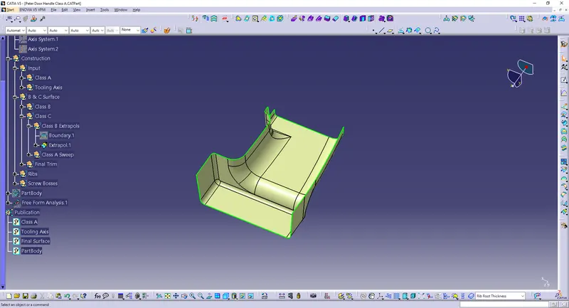
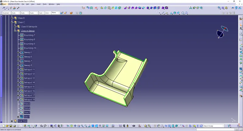
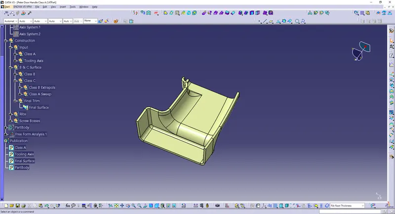
The C surface:
Rib:
Height 3:1, h = Wall thickness * 3 = 2.5*3 = 7.5 mm
Rib Wall Thickness, w = 0.4*t = 0.4*2.5 = 1 mm
Draft Angle = 0.5°
Fillet Radii = 0.625mm
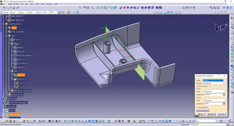
Rib root thickness analysis:
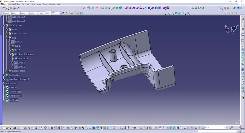
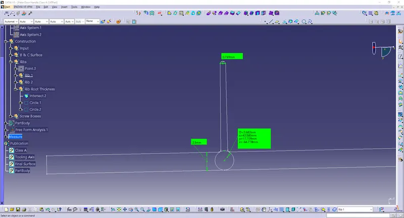
Hence, the Rib satisfies the design requirements.
Screw Boss:
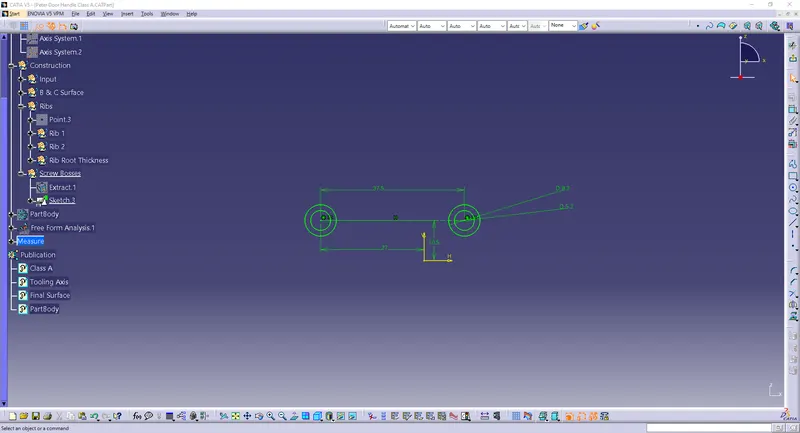
Height 3:1, h = Wall thickness * 3 = 2.5*3 = 7.5 mm
Screw Boss Wall Thickness, w = 0.6*t = 0.6*2.5 = 1.5 mm
Draft Angle = 0.5°
Fillet Radii = 0.625mm
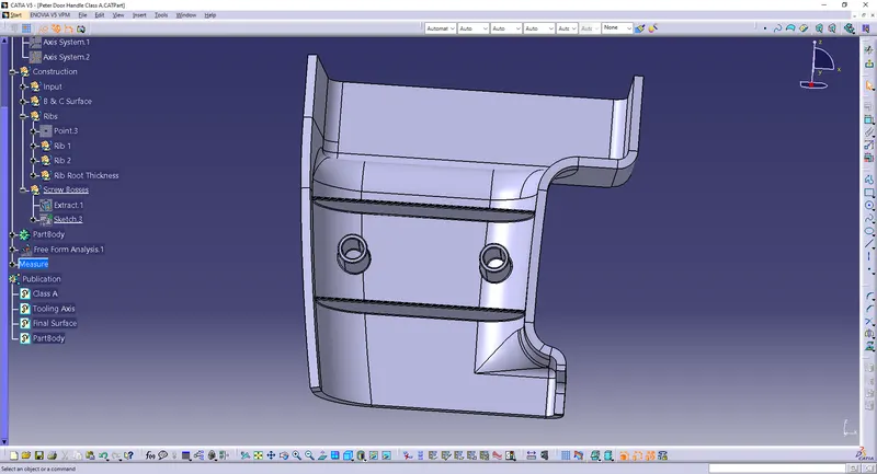
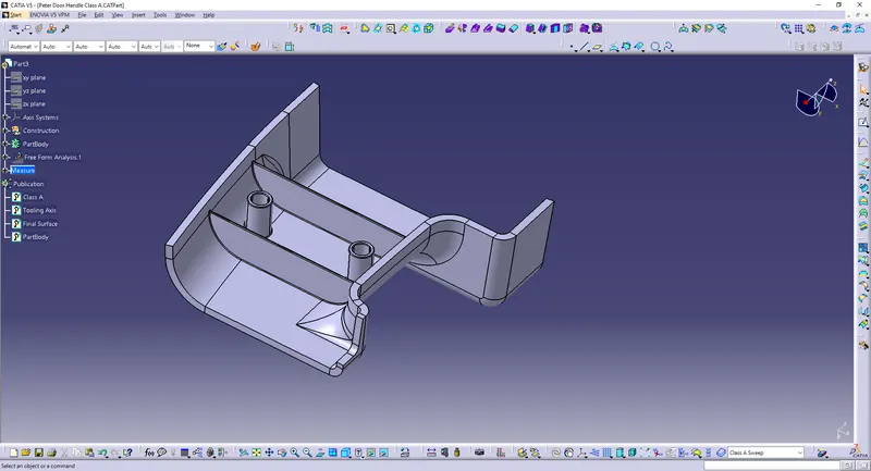
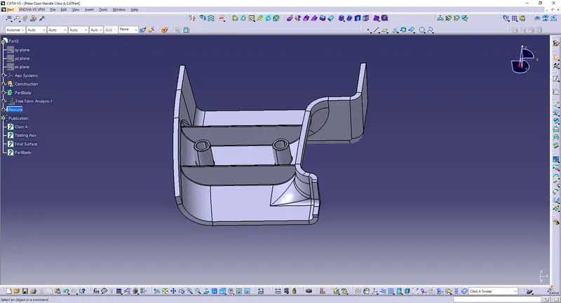
Final:
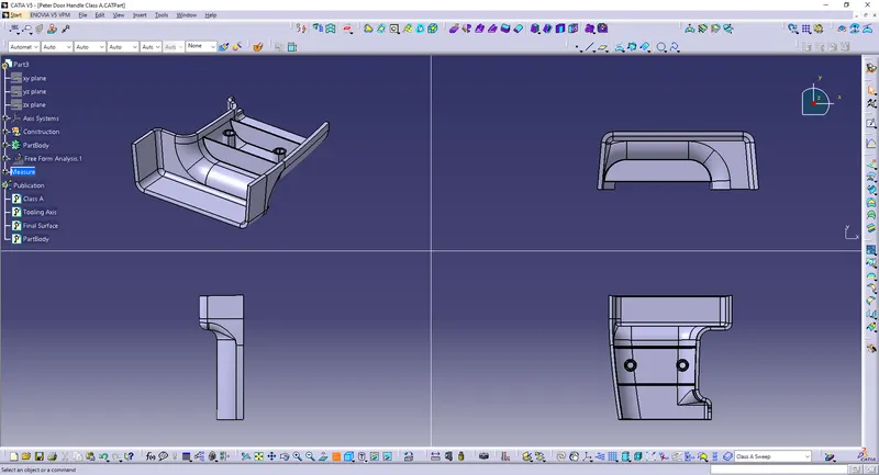
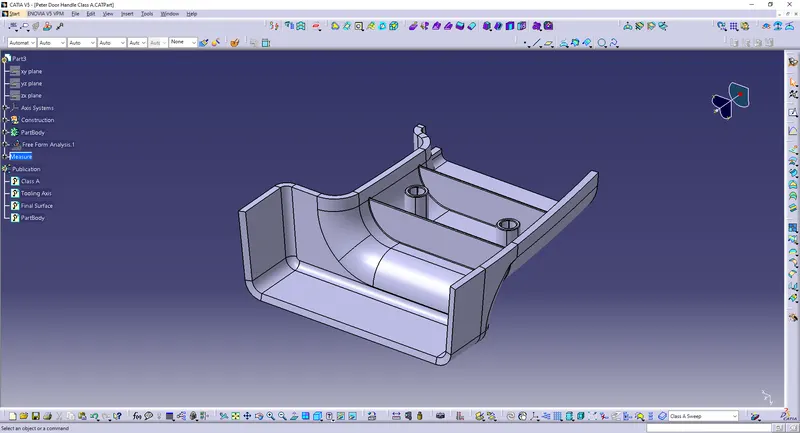
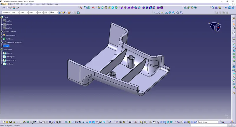
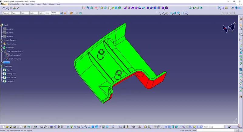
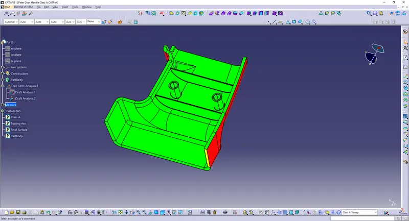
Draft analysis:
The draft analysis is done to determine if the designed part is tool able or not. Here the tooling axis is 3°.
By using the compass option, drag and place it on the tooling axis. Click ok then check the result.
Conclusion:
The part has been designed as per the design requirements.