Wiring harness design in CATIA V5 - 3D modeling Week 2 Challenge
Wiring harness design in CATIA V5 - 3D Modeling
Objective:
Download the following connectors & connector clip cad data from the given link & define it as Electrical Connector using the Electrical Part Design Workbench. Define all the necessary properties of Connectors & Clip.
Procedure:
Creating a catalog for connectors:
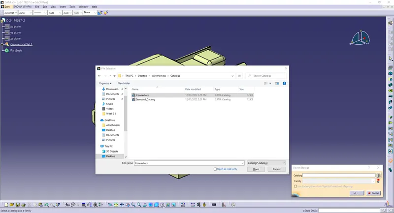
Go to File>New>CatalogDocument
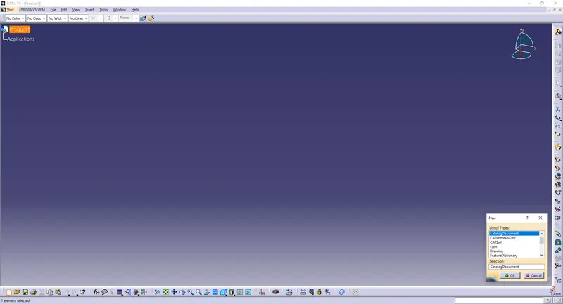
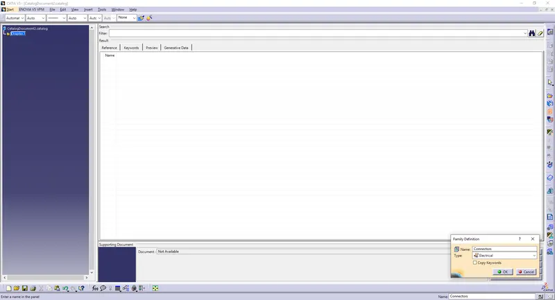
Name it Connectors
Type: Electrical
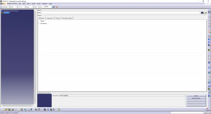
Save it to the desired location.
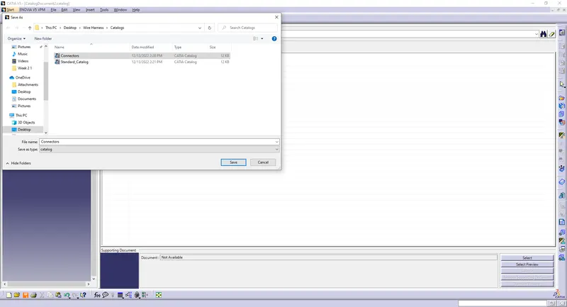
Now, we can save the imported or downloaded connector in the connectors catalog to use it in the future.
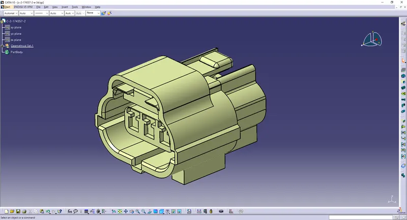
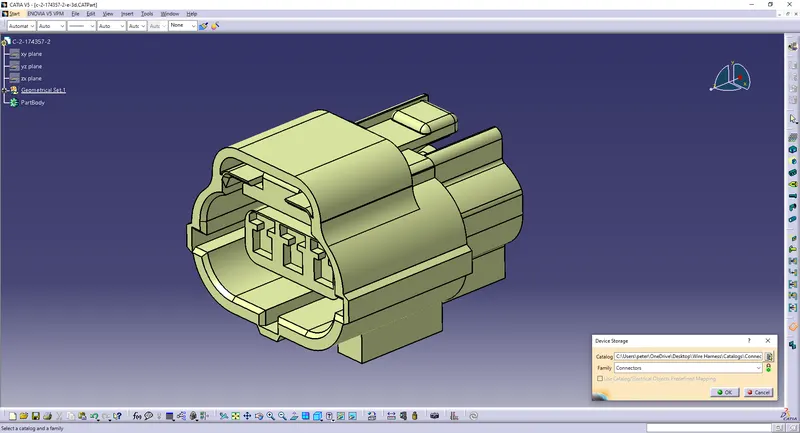
Import the three given files in CATIA V5.
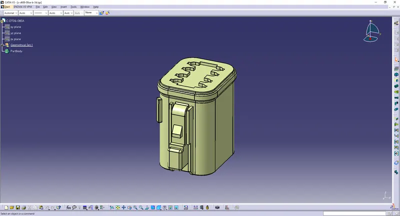
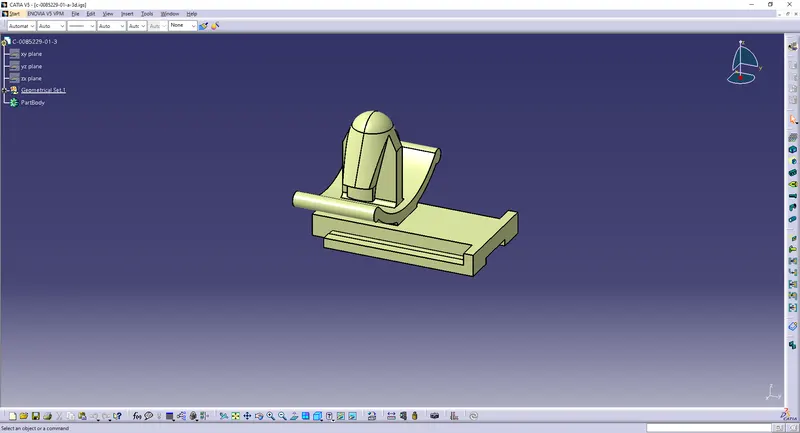
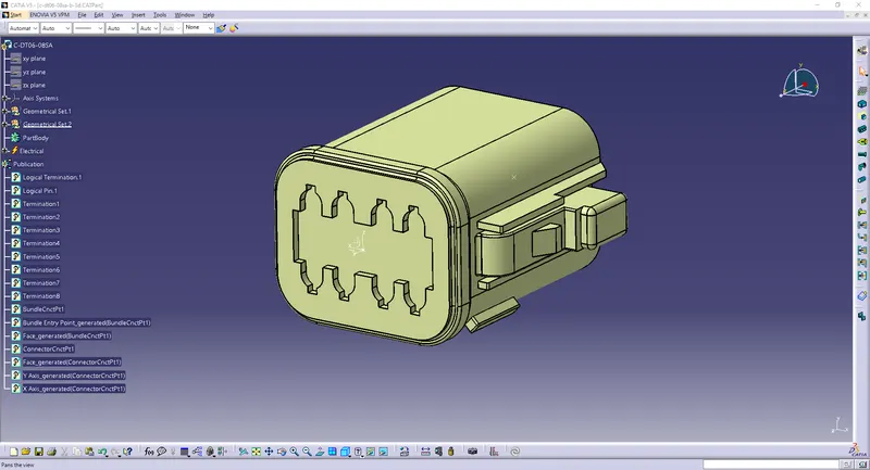
1)First Connector:
Create a point on the mating surface.
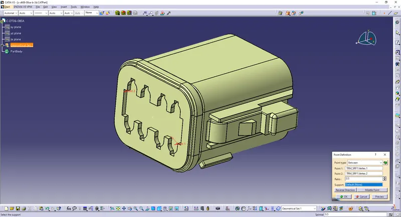
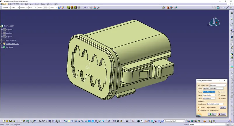
Create an axis on the point.
Create a point at the back as the bundle entry point.
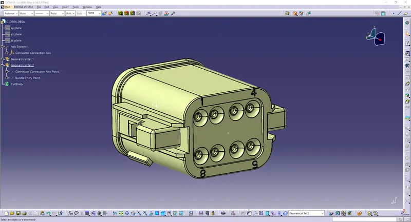
Now define the part as a connector with 8 terminations.
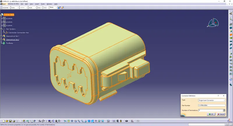
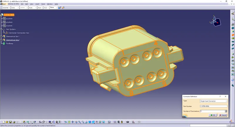
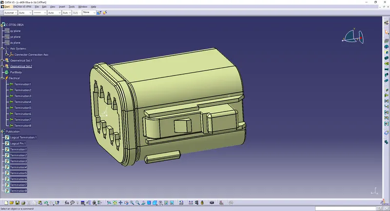
Define Bundle Connection Point.
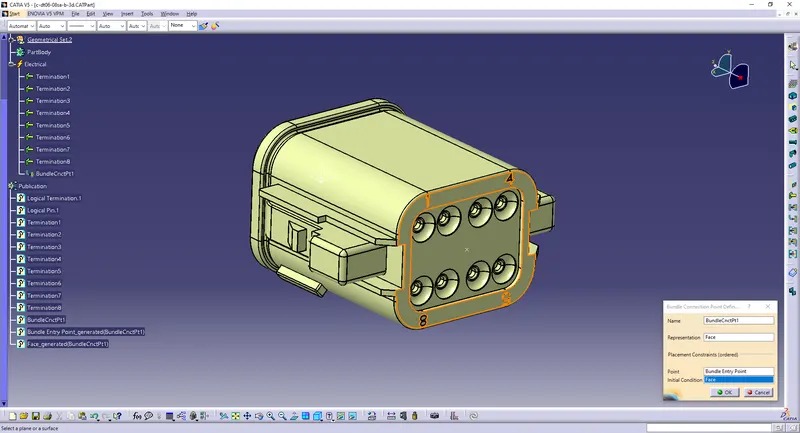
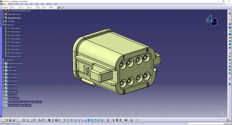
Define Connector Connection Point.
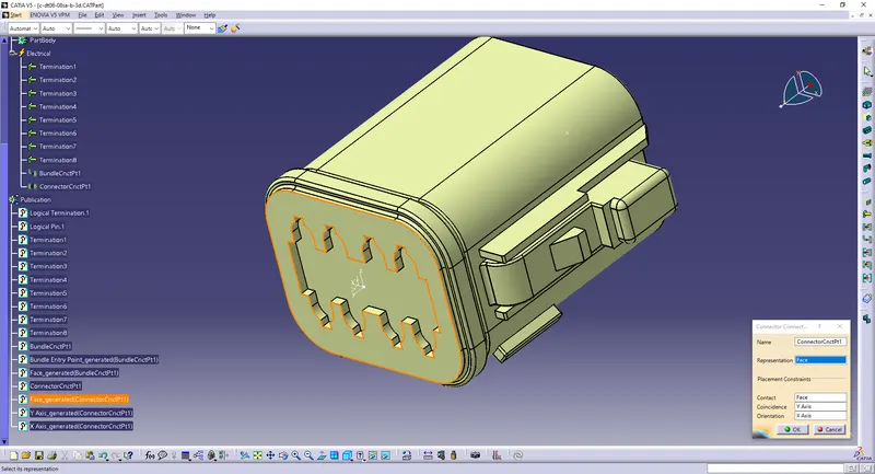
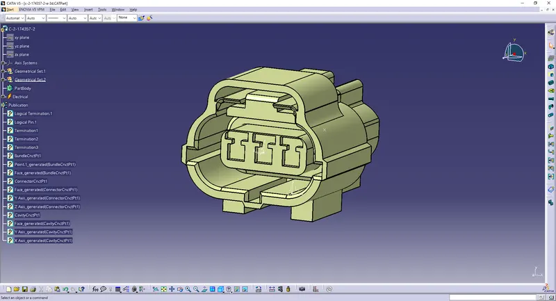
2)Second Connector:
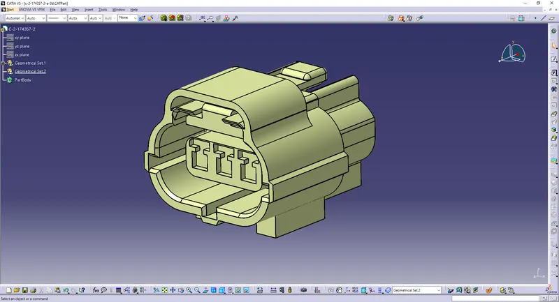
Create a point on the mating surface.
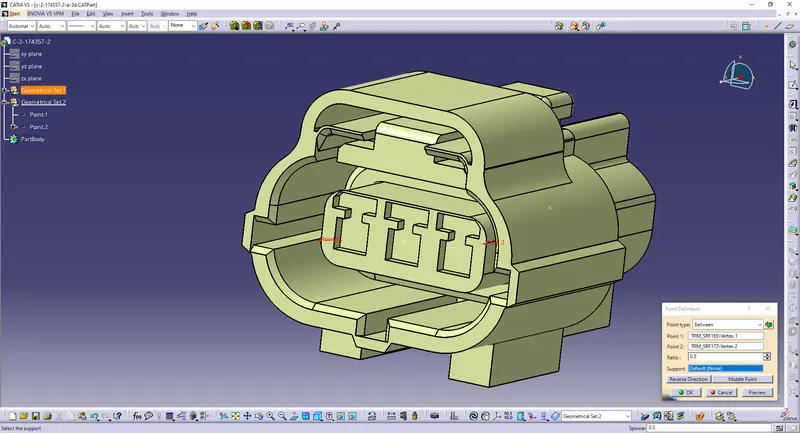
Create a point at the back as the bundle entry point.
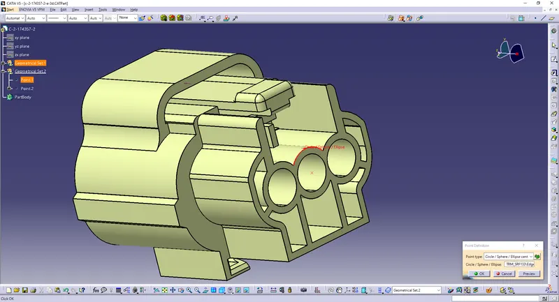
Create a point at the bottom as the cavity connection point.
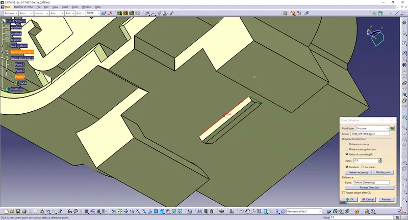
Create an axis on the points
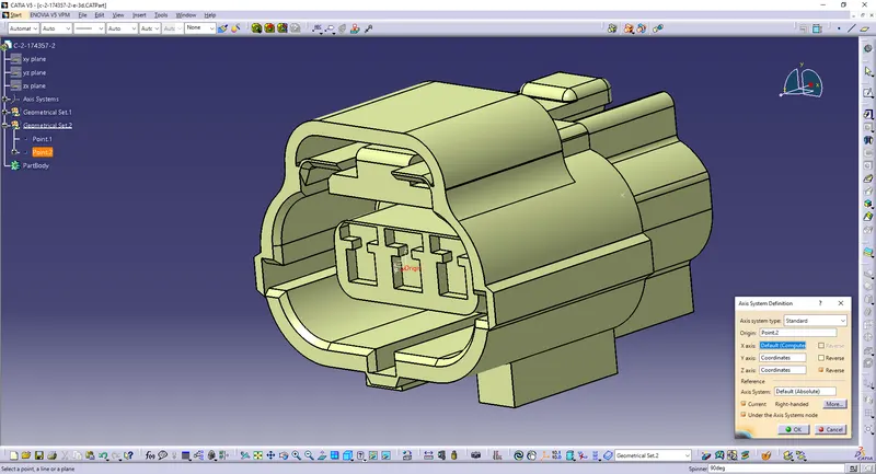
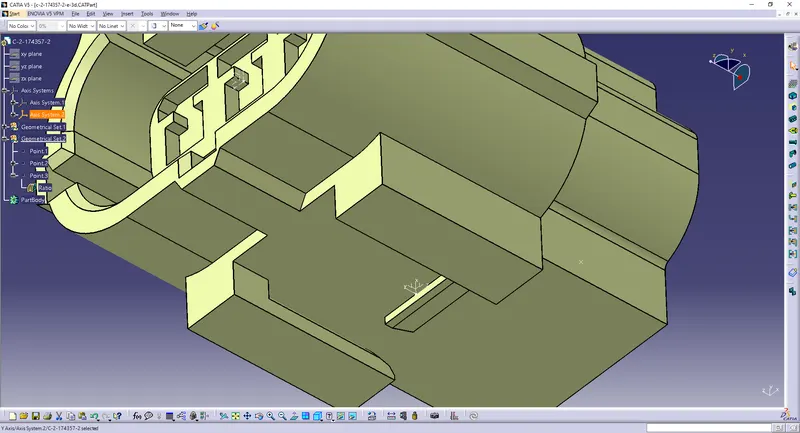
Now define the part as a connector with 3 terminations.
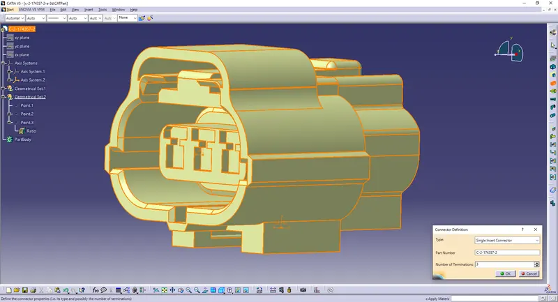
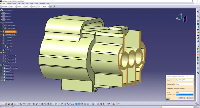
Define Bundle Connection Point.
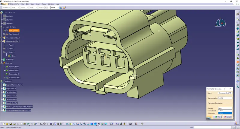
Define Connector Connection Point.
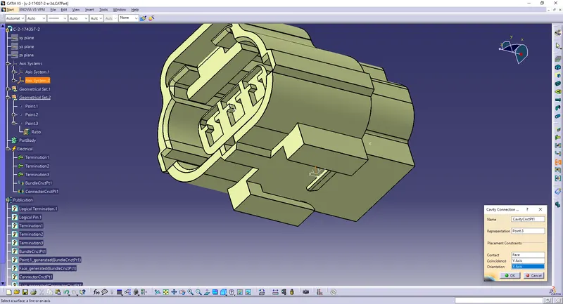
Define Cavity Connection Point.
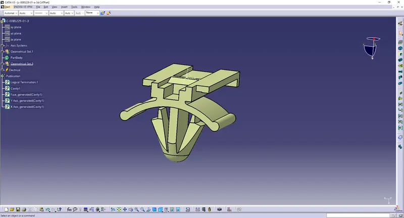
3)Clip:
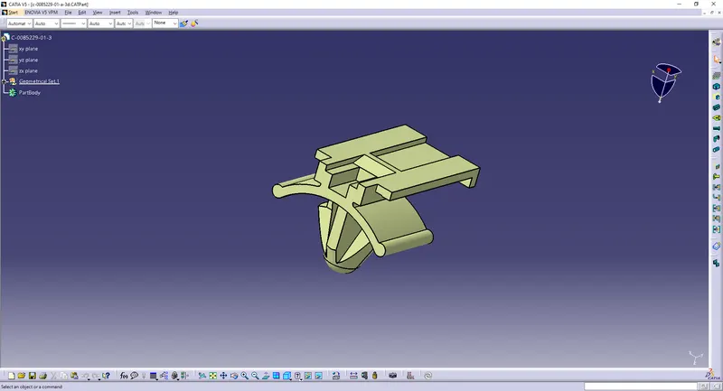
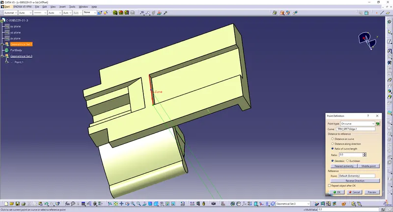
Create a point.
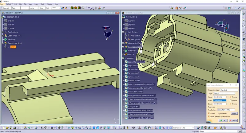
Create an axis on the point.
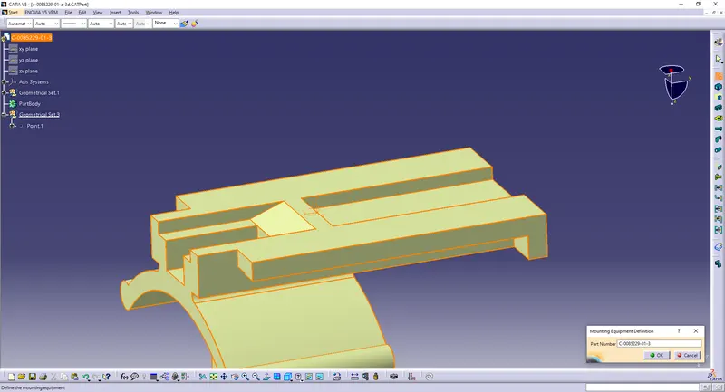
Define Cavity.
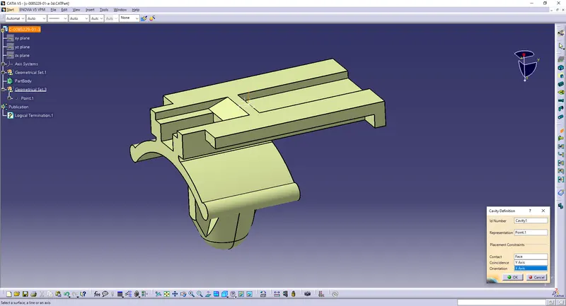
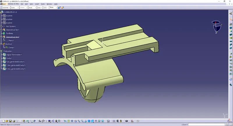
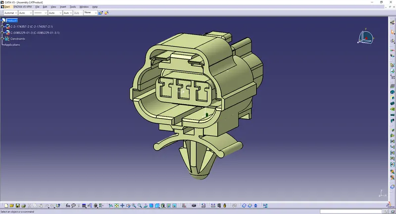
Assembly:
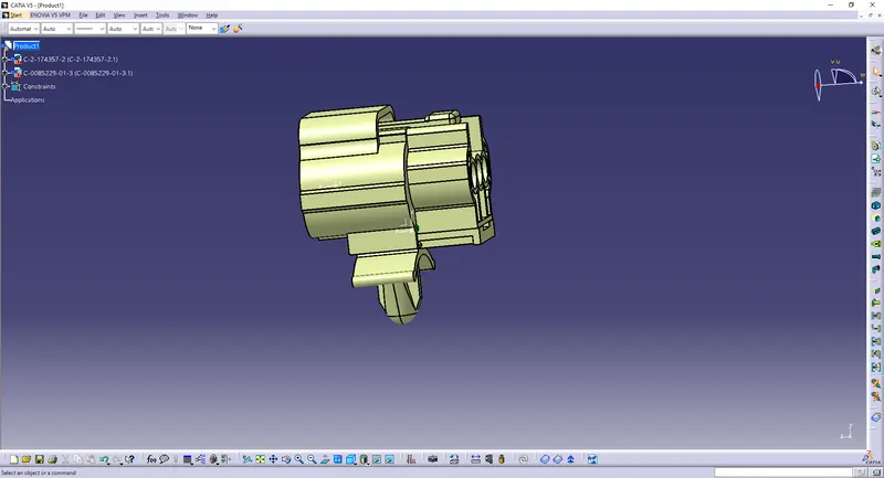
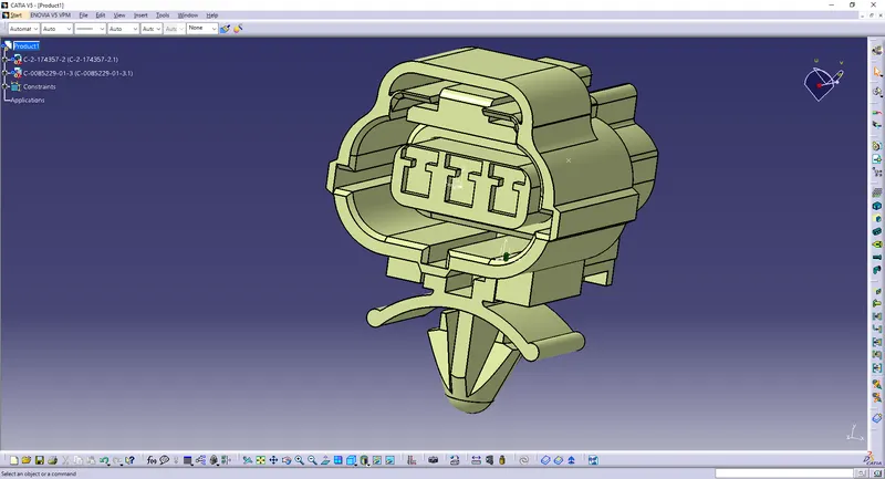
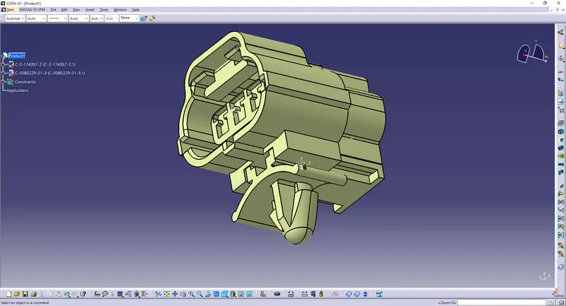
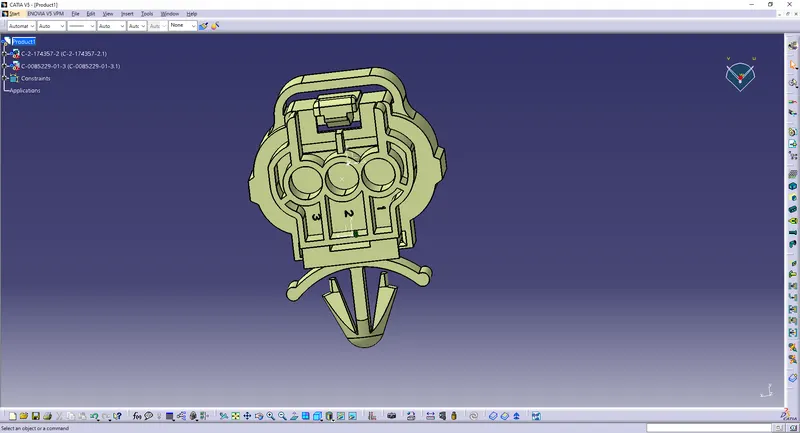
Open the connector and clip in 'Electrical Assembly Design workbench
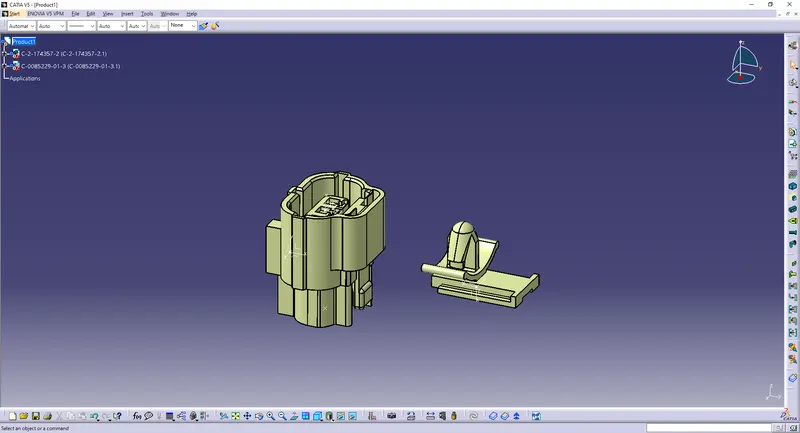
Align them properly.
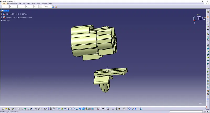
Use to 'Connect Electrical Devices' option to connect them.
Conclusion
All the necessary properties of Connectors & Clip are Defined.