Fender Design Challenge
Front Fender Design
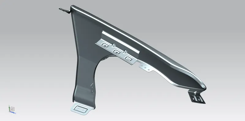
Objective:
Design Front Fender by following the Master Section mentioned with the Design parameters. Providing mount for the Sill, Bumper, Baffle (Splash), and A-Pillar.
Introduction:
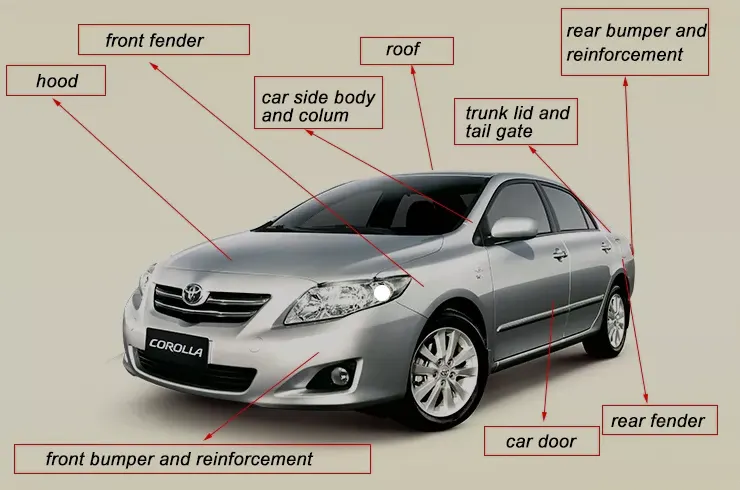
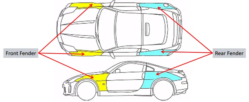
Fender is the American English term for the part of an automobile, motorcycle, or other vehicle body that frames a wheel well. The Front Fender is the metal structure that extends between the front door and the front bumper. Its primary purpose is to provide necessary protection for front wheels and to prevent sand, mud, rocks, liquids, and other road spray from being thrown into the air by the rotating tire. The fender is designed according to the pedestrian’s safety. Fenders are typically rigid and can be damaged by contact with the road surface.
Sticky materials, such as mud, may adhere to the smooth outer tire surface, while smooth loose objects, such as stones, can become temporarily embedded in the tread grooves as the tire rolls over the ground. These materials can be ejected from the surface of the tire at high velocity as the tire imparts kinetic energy to the attached objects. For a vehicle moving forward, the top of the tire is rotating upward and forward and can throw objects into the air at other vehicles or pedestrians in front of the vehicle.
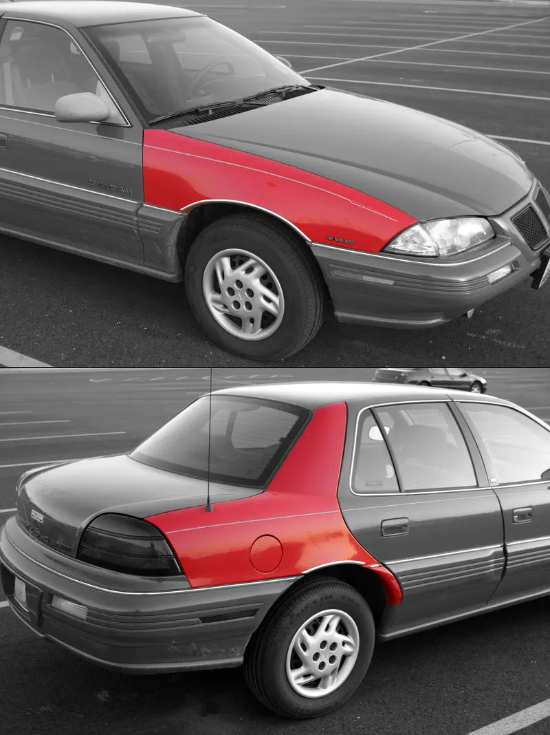
In British English, the fender is called the wing. This may refer to either the front or rear fenders. However, in modern unibody vehicles, rear fenders may also be called quarter panels. The equivalent component of a bicycle or motorcycle, or the "cycle wing" style of wing fitted to vintage cars, or over tires on lorries which is not integral with the bodywork, is called a mudguard in Britain, as it guards other road users – and in the case of a bicycle or motorcycle, the rider as well – from mud, and spray, thrown up by the wheels.
In modern Indian and Sri Lankan English usage, the wing is called a mudguard.
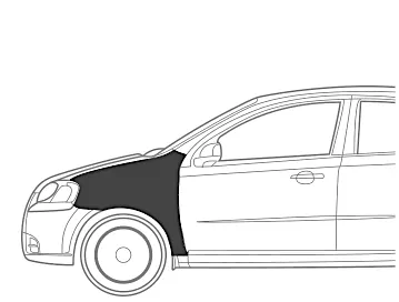
A quarter panel in British English as the rear wing is the body panel (exterior surface) of an automobile between a rear door or only door on each side for two-door models and the trunk (boot) and typically wraps around the wheel well.
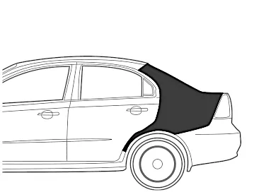
The similar front section between the door and the hood (bonnet) is called a fender (front wing), and may sometimes also be referred to as a quarter panel.
Quarter panels are typically made of aluminium or sheet metals, but are sometimes made of fiberglass, carbon fiber, or fiber-reinforced plastic.
A quarter panel is typically a welded-on component of the unibody structure. Replacement of a sheet metal quarter panel typically requires it to be cut off the vehicle and a replacement part to be welded (or sometimes bonded) to the vehicle. Due to the high amount of specialized labor, a quarter panel may often be repaired rather than replaced by hammering the damaged area to a relatively flat surface and then applying a body filler to smooth out the damaged area to match the original surface. The panel is then usually painted and often clear coated.
Types of Front Fenders:
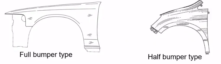
1. Full Bumper Type:
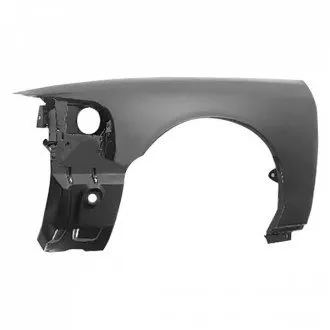
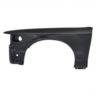
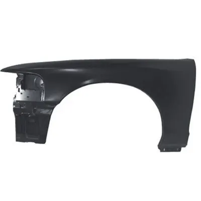
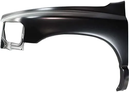
This type is a traditional type of fender where more material consumption is observed. This type of fender is used in the old designs of automobiles where it increases the overall weight and thus reduces the performance of the car.
These are not commonly used because scrap production is more during manufacturing. The sheet of steel or aluminium used to produce this type would result in more wastage of raw materials. Hence, they are not economically good to manufacture as it creates wastage of material and unnecessary increase in manufacturing cost.
2. Half bumper type:
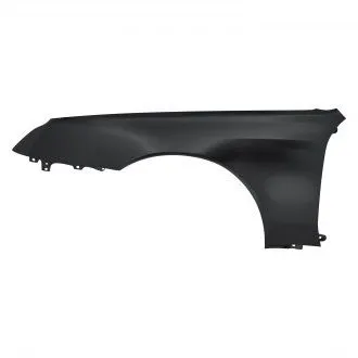
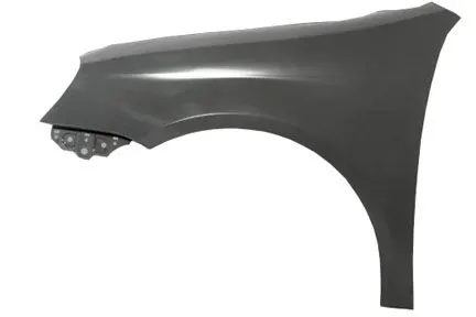
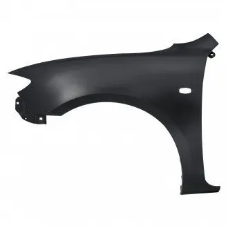
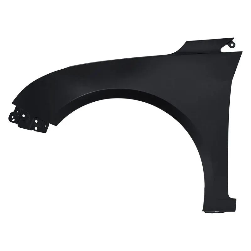
This type of fender is most commonly used. This type is the advanced and modern design where material consumption is relatively low as compared to full type fender. Productivity is increased as the material requirement is less and the weight of the vehicle decreases thus providing more performance. The maintenance is also relatively low compared to the full bumper type.
This half bumper type is used for mainly cost and material cutting purposes as this type also provides ease of manufacturing and the strength is also improved for the half bumper type fender.
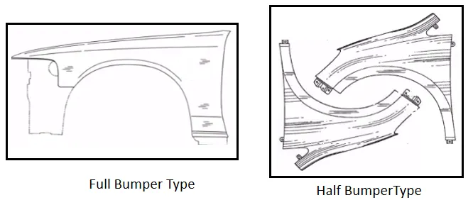
Most of the manufacturers have switched from full bumper type to half bumper type to reduce the scrap rate per sheet. For the full bumper type, we can produce one fender per sheet, whereas in the half bumper type we can produce two fenders for the material of the sheet.
Manufacturing Process:
Stamping (Metal Working)
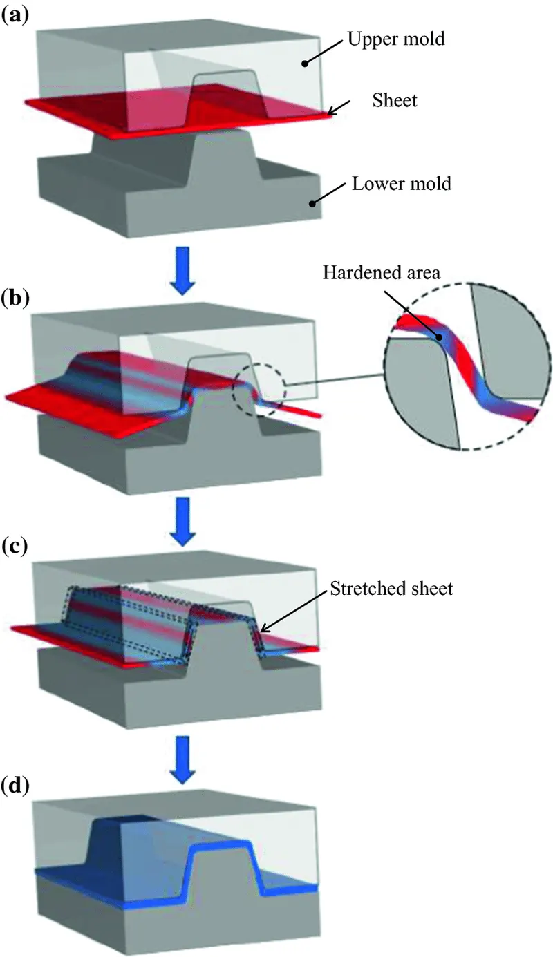
Stamping (also known as pressing) is the process of placing flat sheet metal in either blank or coil form into a stamping press where a tool and die surface form the metal into a net shape. Stamping includes a variety of sheet-metal forming manufacturing processes, such as punching using a machine press or stamping press, blanking, embossing, bending, flanging, and coining. This could be a single-stage operation where every stroke of the press produces the desired form on the sheet metal part, or could occur through a series of stages. The process is usually carried out on sheet metal, but can also be used on other materials, such as polystyrene. Progressive dies are commonly fed from a coil of steel, coil reel for unwinding of the coil to a straightener to level the coil, and then into a feeder which advances the material into the press and die at a predetermined feed length. Depending on part complexity, the number of stations in the die can be determined.
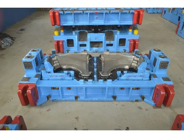
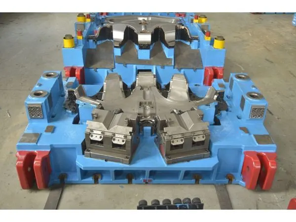
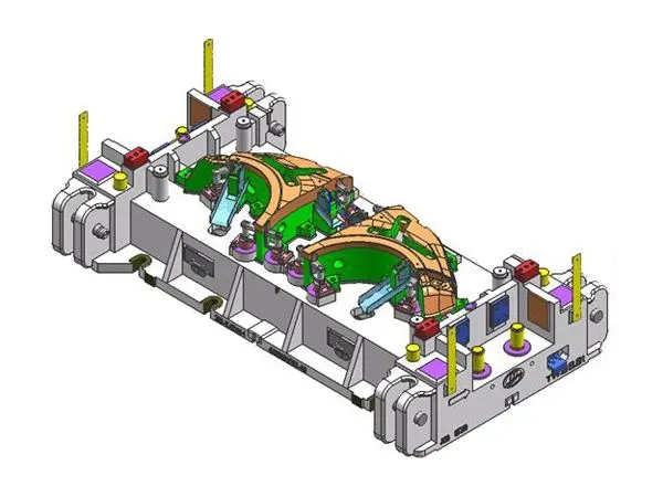
There are three popular types of metal stamping presses used for automotive and other industrial parts. They include:
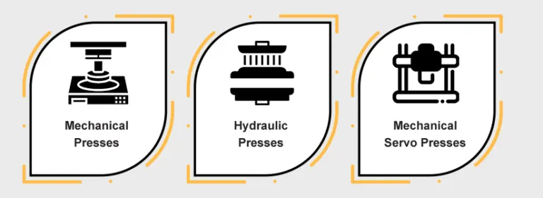
- Mechanical presses - These have a mechanical flywheel powered by a motor.
- Hydraulic presses - These have pressurized fluids that control the pressure and application of force on a workpiece.
- Mechanical servo presses - These use only motors and no mechanical flywheels.
All three press types can work with automated systems, such as automatic feeders, to increase efficiency and production speed. Automatic feeders send coiled or blank sheet metal through the presses to create a fast run.
Main Pressing Operations:
- Bending - The material is deformed or bent along a straight line.
- Flanging - The material is bent along a curved line.
- Embossing - The material is stretched into a shallow depression.
- Blanking - A piece is cut out of a sheet of the material, usually to make a blank for further processing.
- Coining - A pattern is compressed or squeezed into the material.
- Drawing - The surface area of a blank is stretched into an alternate shape via controlled material flow. See also deep drawing.
- Stretching - The surface area of a blank is increased by tension, with no inward movement of the blank edge. Often used to make smooth auto body parts.
- Ironing - The material is squeezed and reduced in thickness along a vertical wall. Used for beverage cans and ammunition cartridge cases.
- Reducing/Necking - Used to gradually reduce the diameter of the open end of a vessel or tube.
- Curling - Deforming material into a tubular profile. Door hinges are a common example.
- Hemming - Folding an edge over onto itself to add thickness. The edges of automobile doors are usually hemmed.
Piercing and cutting can also be performed in stamping presses. Progressive stamping is a combination of the above methods done with a set of dies in a row through which a strip of the material passes one step at a time.
Master Section/Design Parameters:
- The mounting sections are created according to the Master Section.
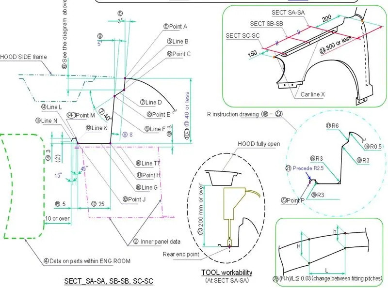
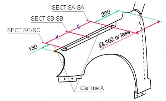
- The drip area should be 150 mm from the Front Side/Headlamp and 300 mm or less from the Cowl/Rear Side/A-Pillar.
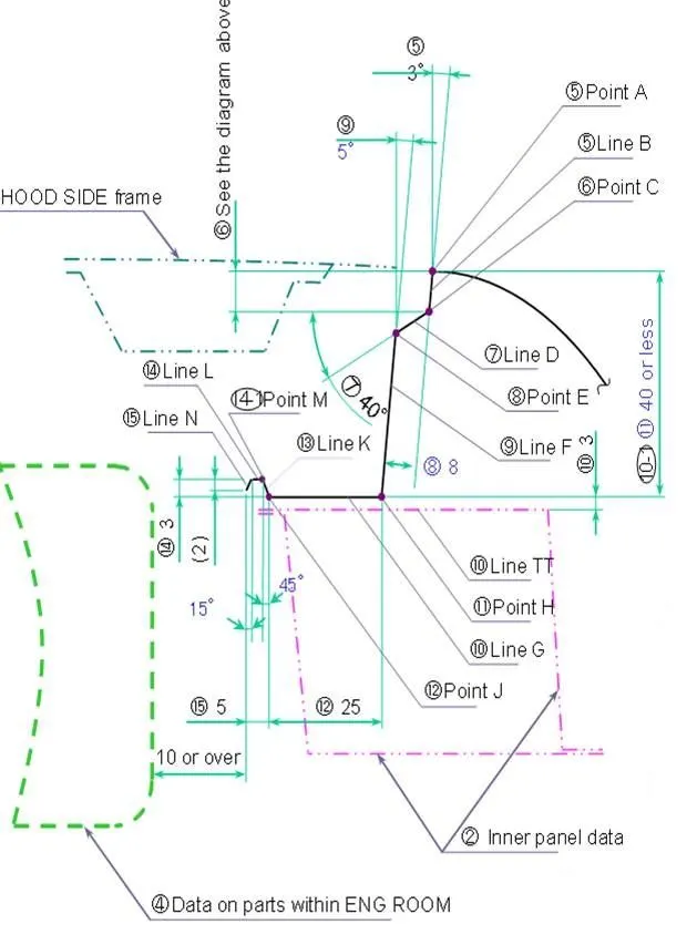
- The total height/length of the drip area from the top of the fender should be less than 40mm, this is to avoid the spring back effect during the manufacturing. The edge of the mounting should be at least 10mm away from any nearby component in the engine. A rigidity bead is provided at the end to increase the strength of the mounting.
- Make sure all the mounting surface area is a flat surface.
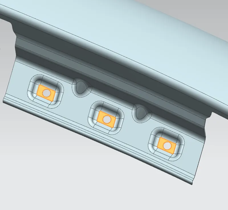
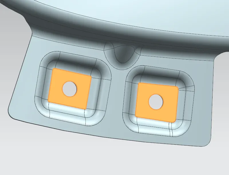
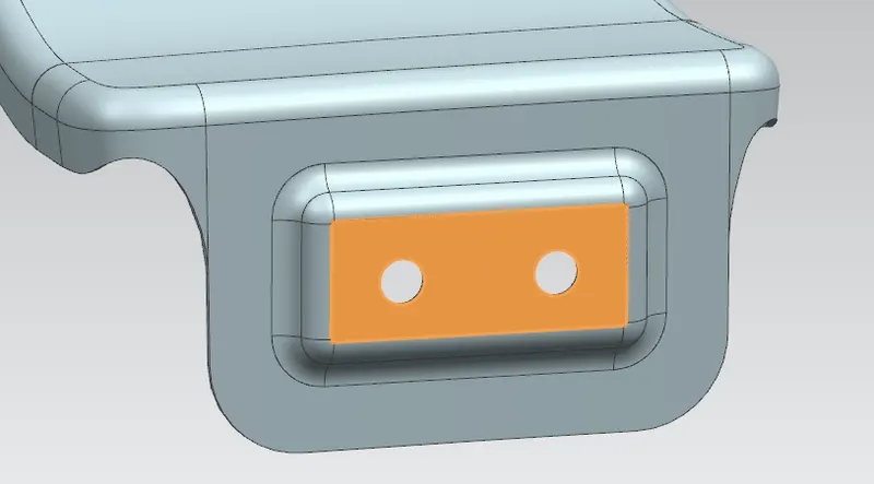
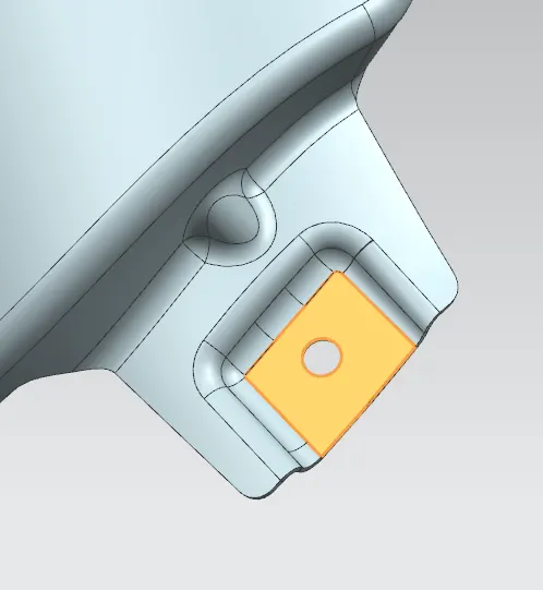
- The minimum gap between the holes and edge should be at least then 5 mm to satisfy manufacturing/design parameters.
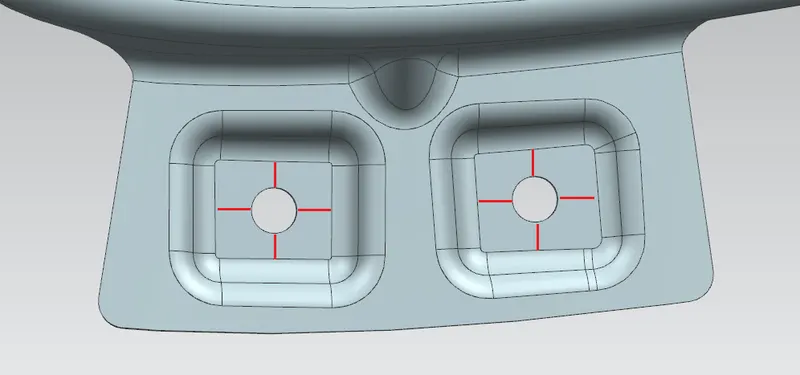
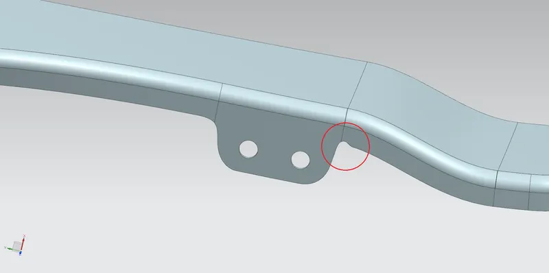
- Providing relief where ever necessary.
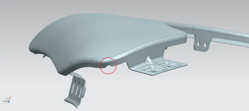
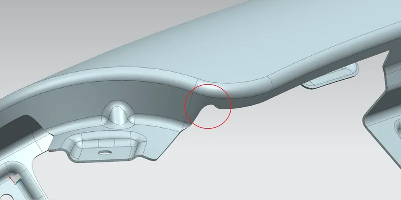
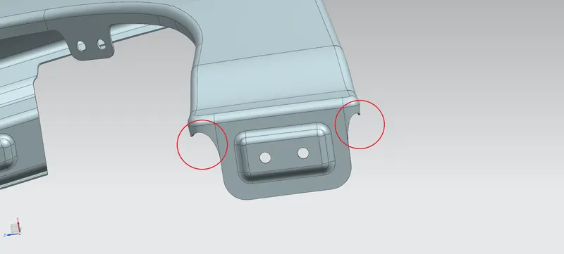
Mounting Region:
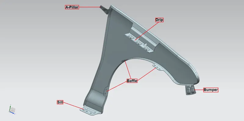
- A-Pillar Mounting: This is the mounting area that attaches the fender to the A-pillar. The A-pillar area mounting depends upon the A-Pillar of the car.
- Drip Mounting: This is the mounting area located near the car engine compartment. It is placed at a distance of 200 to 300 mm from the Cowl/A-Pillar and 150mm from the Front Side/Headlamp. A distance of 10 mm or more is maintained between the drip area inside the fender and the engine compartment. The total height/length should be less than 40mm.
- Sill Mounting: This is the mounting area situated on the bottom of the fender, which attaches the fender to the Sill of the car.
- Bumper Mounting: This is the mounting area of the fender where the fender attaches to the bumper.
- Baffle Mounting: This is the mounting area where the fender attaches to the mudguard splash.
Design Procedure:
Fender Design using NX CAD
Commands Used:
Datum Plane: This command is used to create a datum plane to construct other features.
Sketch Commands: Line, Arc, Circle, Rectangle, Fillet, Quick Trim, and Quick Extend.
Bridge Curve: This command is used to create a tangent blend curve between two objects.
Offset Curve in Face: This command is used to offset curves along the faces on which they lie.
Curve on Surface: This command is used to create a surface spline feature directly on a face.
Law Extension: This command is used to create a law-controlled extension from a base sheet, dynamically or based on laws for distance or angle.
Face Blend: This command is used to add tangent blend faces between selected sets of faces. The blend shape can be circular, conic, or law controlled.
Edge blend: This command is used round sharp edges between faces. The radius can be constant or variable.
Trim Sheet: This command is used to trim off a portion of a sheet body.
Extend Sheet: This command is used to extend a sheet body by distance or to the intersection with another body.
Dart: This command is used to add a dart feature along the intersection curve of two sets of faces
Sew: This command is used to combine sheet bodies by sewing common edges together, or combine solid bodies by sewing common faces.
Thicken: This command is used to a solid body by adding thickness to a set of faces
By using the master section provided, the mounting sections are created.
1. Drip Mounting:
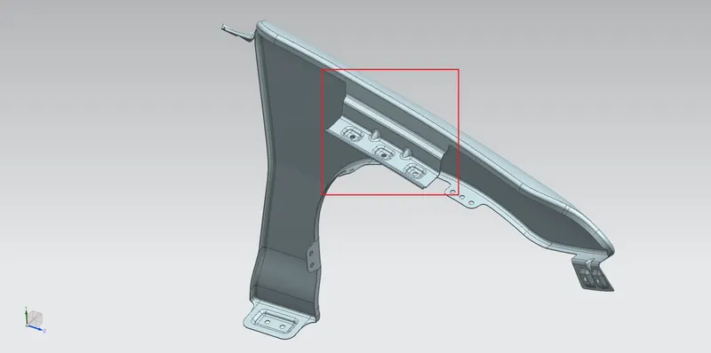
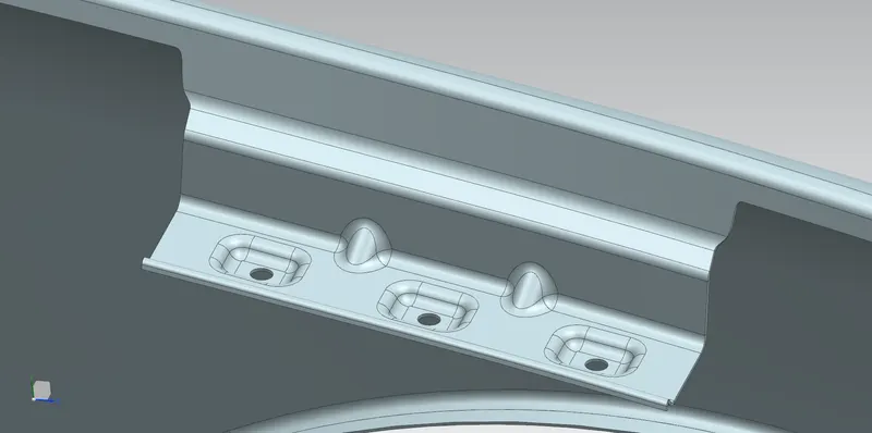
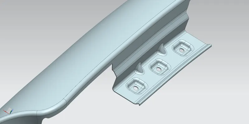
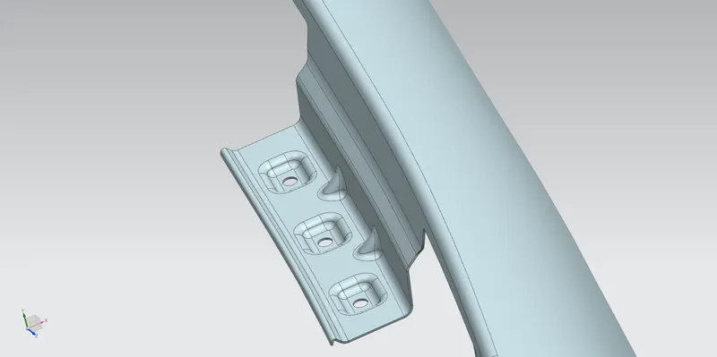
The drip area is 150 mm apart from the front so that it won’t create any problems in the headlamp mounting region.
From the rear side, the drip area is 200 mm apart.
A 10 mm+ distance is maintained with the engine compartment.
The drip section is created using the Law Extension option with an angle of 3˚, 5˚, and 40˚ with provided dimensions according to the master section.
Embosses are created as the Drip mounting region using Emboss option.
Holes of 5 mm in the mounting region are provided using the Trim Sheet option.
Edge blends of radius 3 mm are applied on the corners and edges of the embosses using the Edge Blend option.
Two darts are provided to strengthen the Drip mount using the Dart option.
Edge blends of radius 3 mm and 6 mm and applied between the remaining surfaces using the Edge Blend option, according to the master section.
The remaining unnecessary portions are trimmed out using the Trim Sheet option.
2. A-Pillar Mounting:
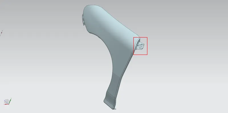
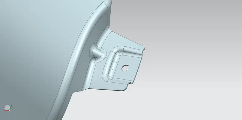
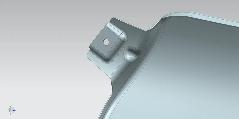
The sheet is extended for about 30 mm using the Law Extension option.
Emboss is created using a Datum Plane to create a flat emboss surface as the A-Pillar mounting region using Emboss option.
A hole of 5 mm is provided in the mounting region using the Trim Sheet option.
Edge blends of radius 3 mm are applied on the corners and edges of the embosses using the Edge Blend option.
Dart is provided to strengthen the A-Pillar mount using the Dart option.
Edge blends of radius 3 mm are applied between the remaining surfaces using the Edge Blend option.
Using the Bridge Curve option, the remaining unnecessary portions are trimmed out using the Trim Sheet option.
3. Sill Mounting:
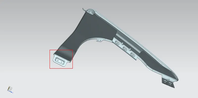
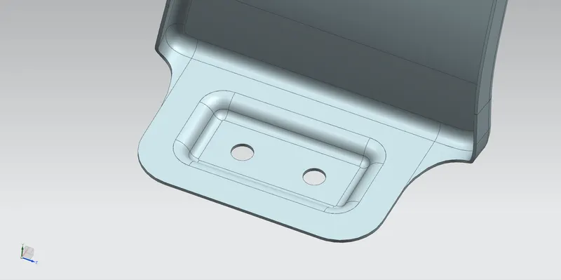
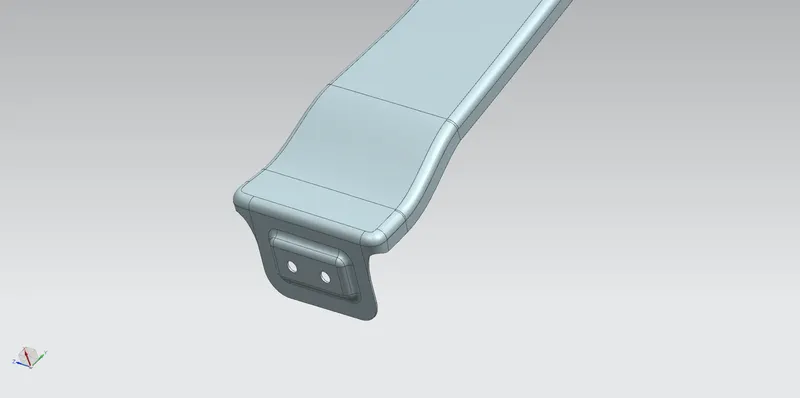
The sheet is extended for about 20 mm using Extend Sheet option.
Emboss is created using a Datum Plane to create a flat emboss surface as the Sill mounting region using Emboss option.
Holes of 5 mm are provided in the mounting region using the Trim Sheet option.
Edge blends of radius 3 mm are applied on the corners and edges of the embosses using the Edge Blend option.
The remaining unnecessary portions are trimmed out using the Trim Sheet option.
4. Bumper Mounting:
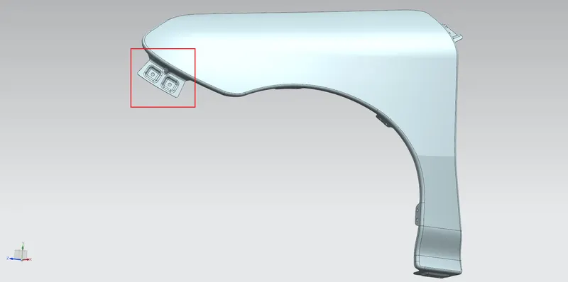
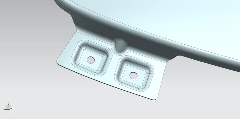
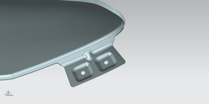
The sheet is extended for about 30 mm using the Law Extension option.
Embosses are created using a Datum Plane to create a flat emboss surface as the Bumper mounting region using Emboss option.
Holes of 5 mm are provided in the mounting region using the Trim Sheet option.
Edge blends of radius 3 mm are applied on the corners and edges of the embosses using the Edge Blend option.
Dart is provided to strengthen the Bumper mount using the Dart option.
Edge blends of radius 3 mm are applied between the remaining surfaces using the Edge Blend option.
The remaining unnecessary portions are trimmed out using the Trim Sheet option.
5. Baffle Mounting:
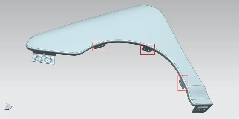
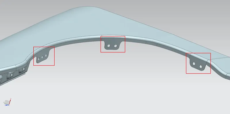
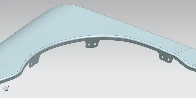
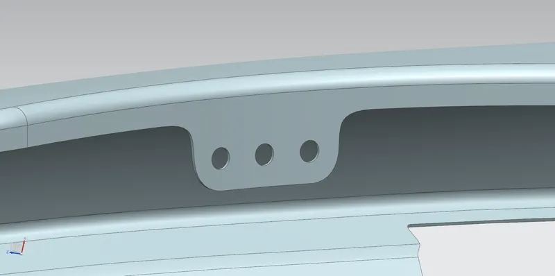
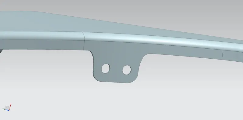
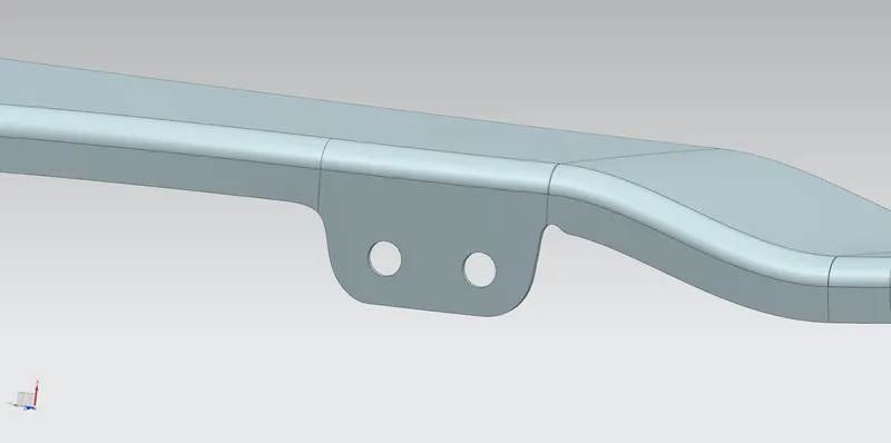
A Datum Plane is created as a sketch reference with respect to these surfaces.
5 mm holes are sketched in each sketch to create holes.
Holes of 5 mm are provided in each mounting region using the Trim Sheet option.
The remaining unnecessary portions are trimmed out using the Trim Sheet option.
Final Result:
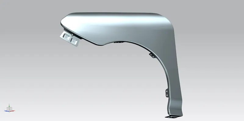
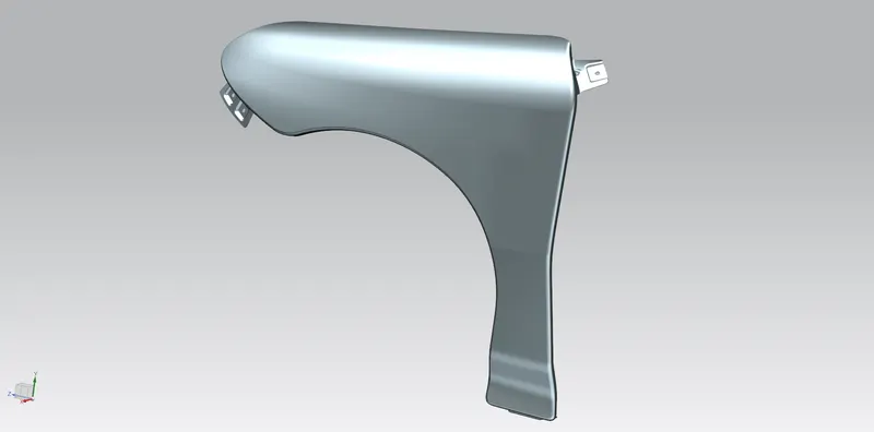
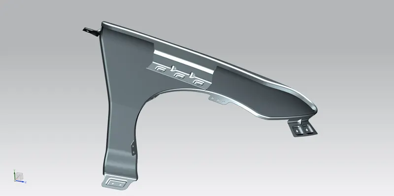
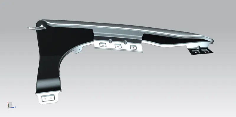
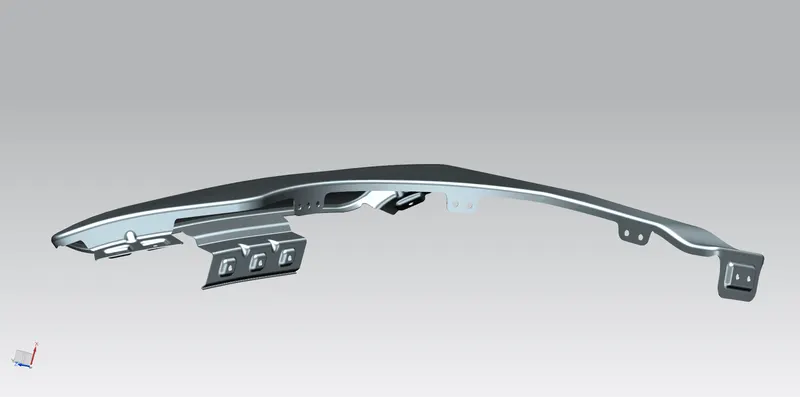
Conclusion:
The front fender is designed according to manufacturing requirements and to the dimensions given in the Master Section.