Wiring harness routing & packaging Rules Week 3 Challenge
Wiring harness routing & packaging rules
Objective:
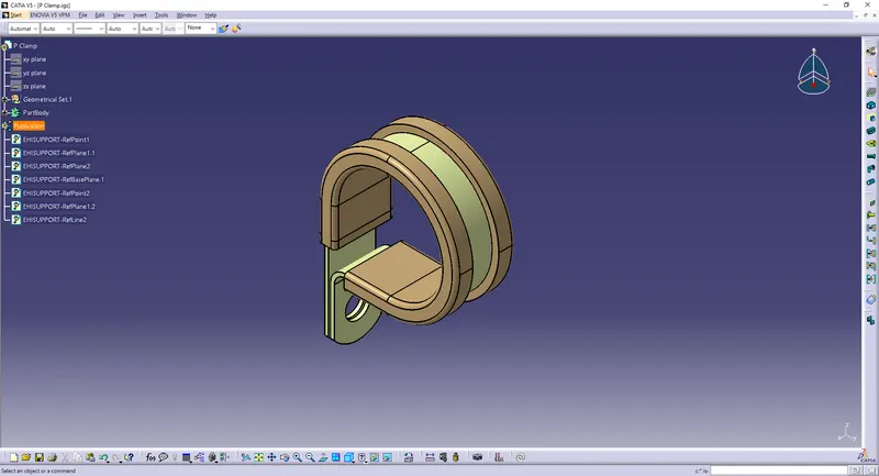
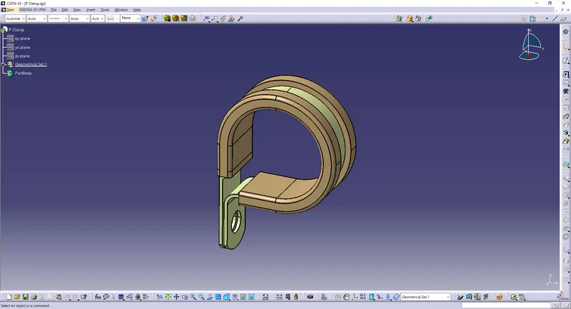
1) Download the P clamp cad data & define it as Electrical support using the Electrical Part Design Workbench. Define all the necessary properties.
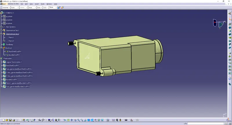
2) Download the 1738312-1 Back shell cad data & define it as an Electrical back shell using the Electrical Part Design Workbench. Define all the necessary properties.
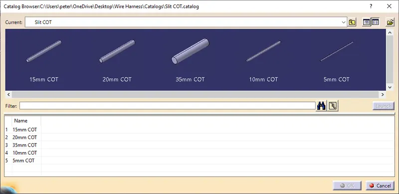
3) Create the Following Corrugated tubes & Add them to the Catalogue under the “Slit COT” family.
|
Name |
ID (mm) |
OD (mm) |
Thickness (mm) |
|
15mm COT |
12 |
15 |
1.5 |
|
20mm COT |
17 |
20 |
1.5 |
|
35mm COT |
32 |
35 |
1.5 |
|
10mm COT |
7 |
10 |
1.5 |
|
5mm COT |
3 |
5 |
1 |
Procedure:
1) P Clamp:
Create 2 points as entry and exit points.
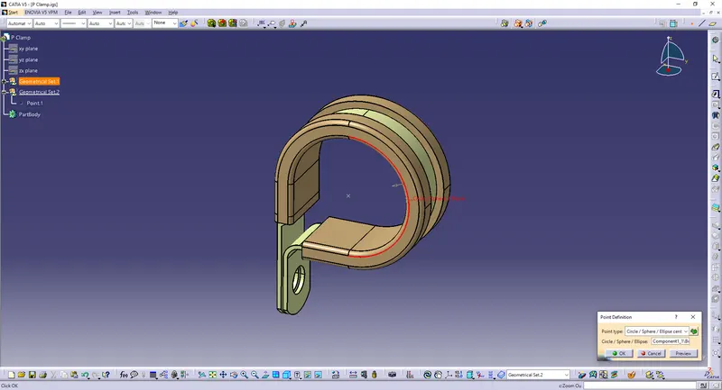
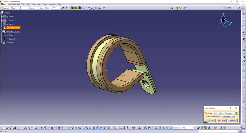
Create 2 planes on these 2 points.
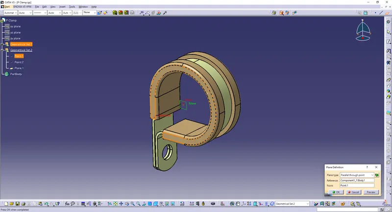
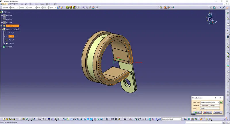
Create a third plane.
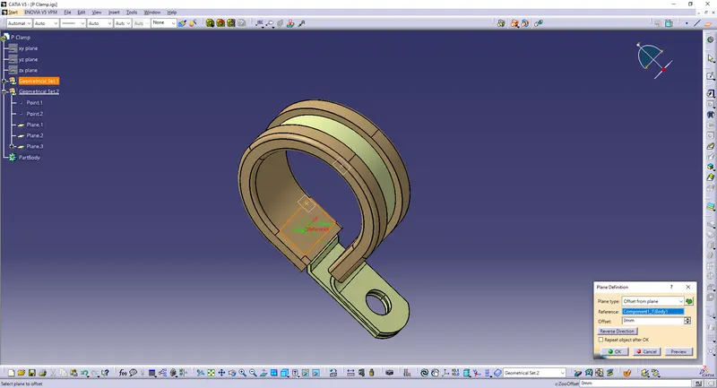
Define Support Part on both sides.
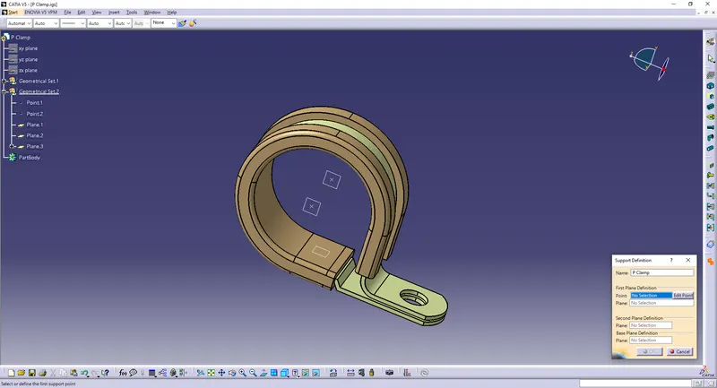
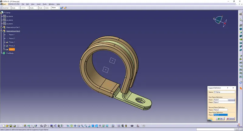
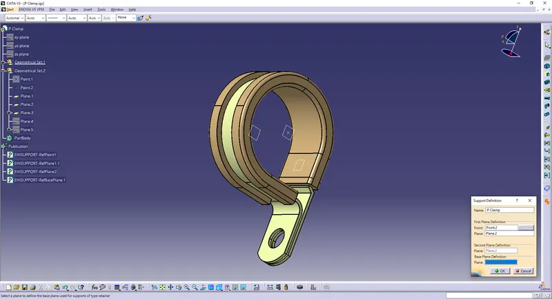
2) Tyco 1738312-1:
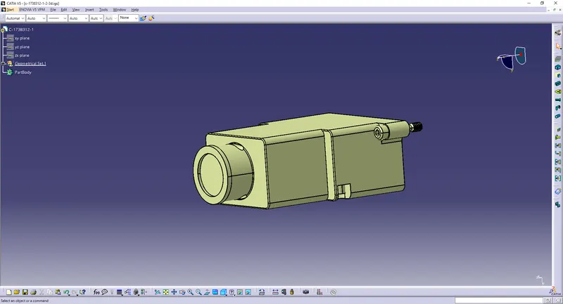
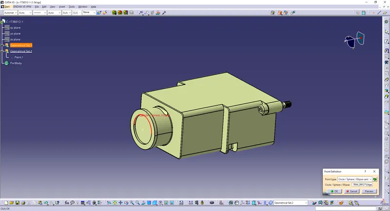
Create 2 points on the front and back.
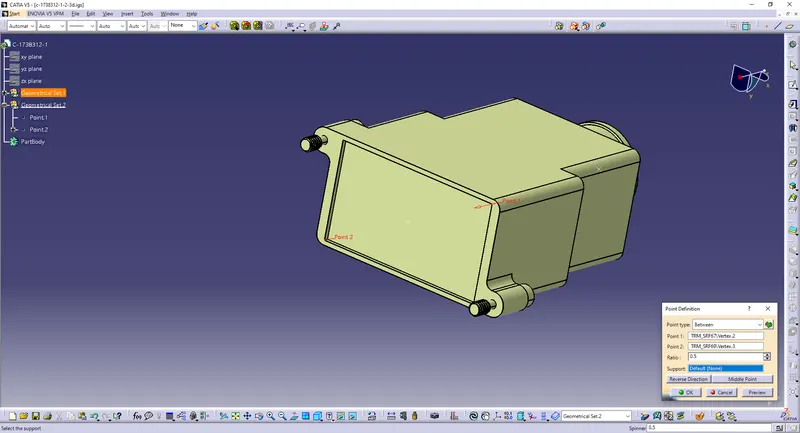
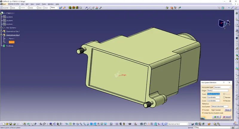
Create an axis.
Define Back Shell.
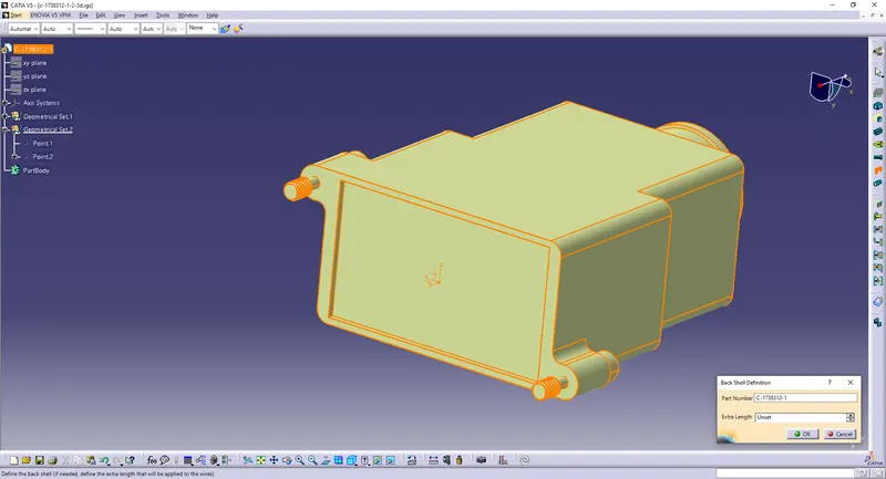
Define Back Shell Connection Point.
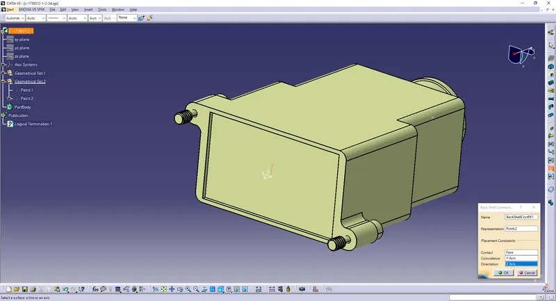
Define Bundle Connection Point.
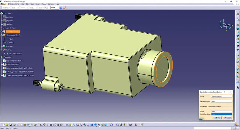
3) Create the Following Corrugated tubes:
Creating a catalog for Corrugated tubes
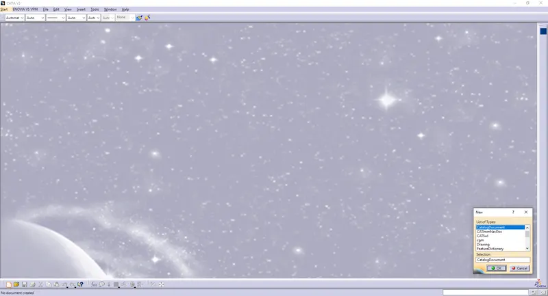
Name it the “Slit COT” family
Type: Conduit
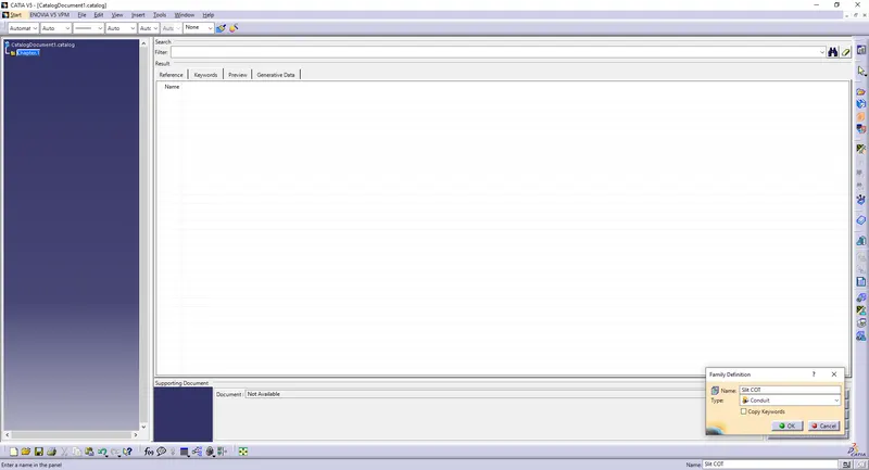
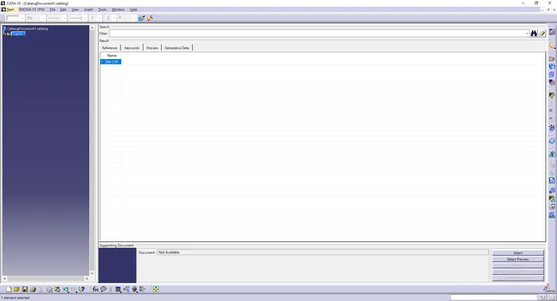
Save it to a location.
Creating Corrugated tubes:
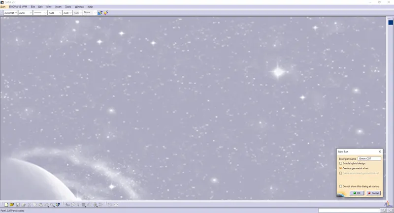
1) 15mm COT
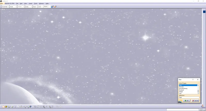
Create a new part file
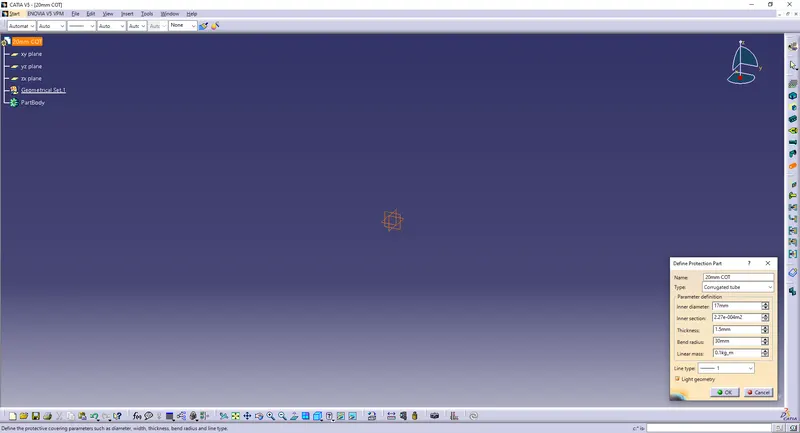
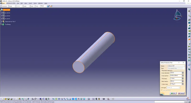
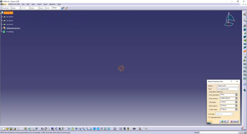
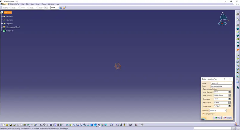
Define Protection Part
Type: Corrugated tube
Bend Radius = OD x 1.5
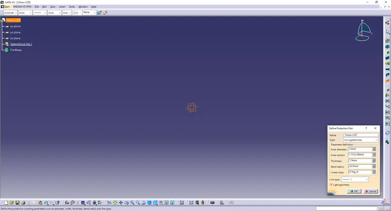
Save the part file.
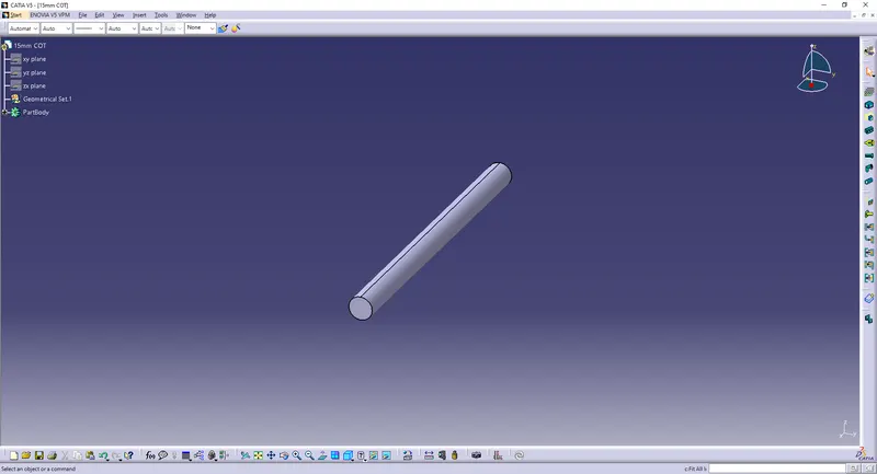
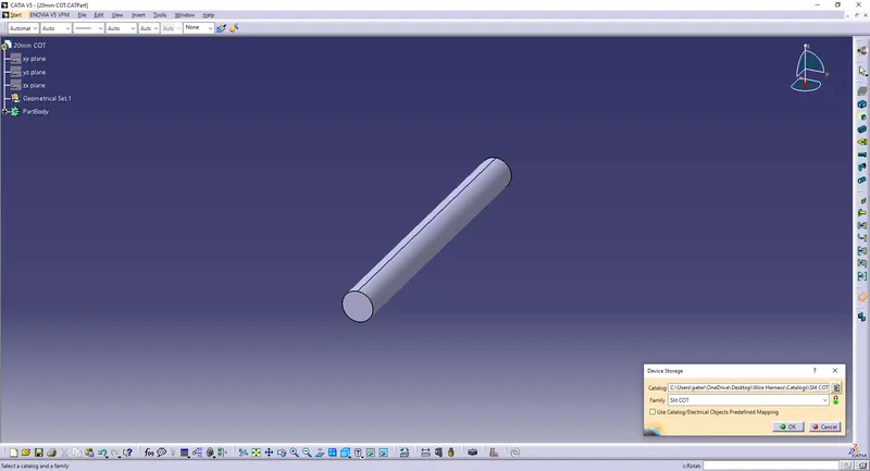
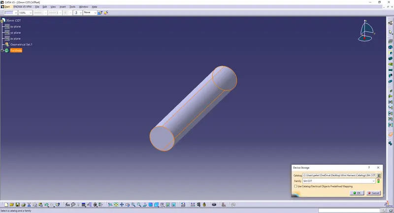
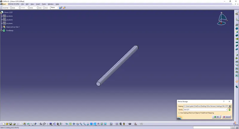
Store Device in the created Slit COT calatog.
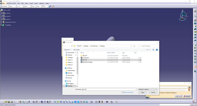
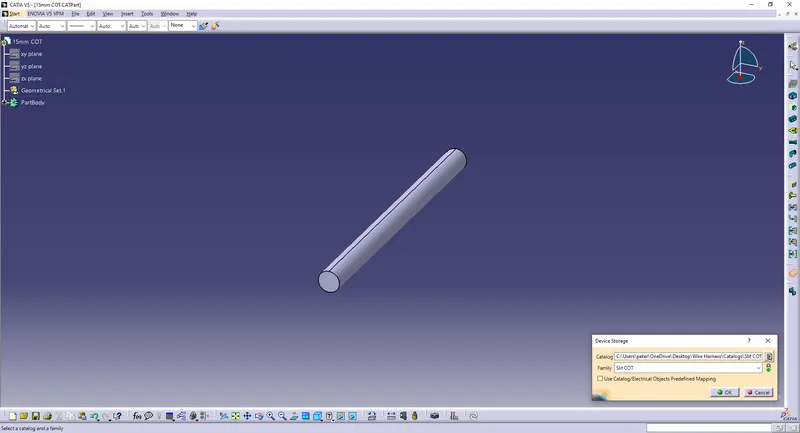
2) 20mm COT
3) 35mm COT
4) 10mm COT
5) 5mm COT
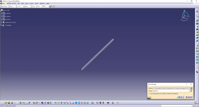
All 5 Corrugated tubes are created.
Conclusion:
All the necessary properties of P Clamp & Tyco 1738312-1 are Defined. All 5 Corrugated tubes are created.