Roof Design
Car Roof Design
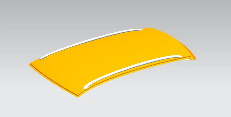
Objective:
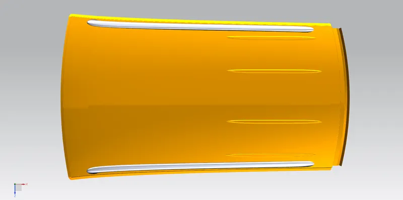
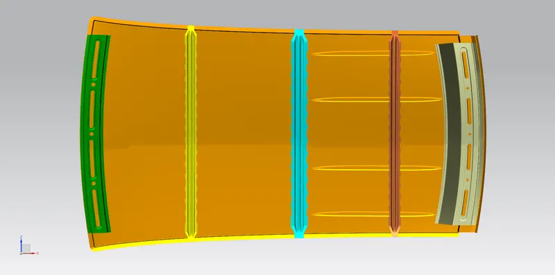
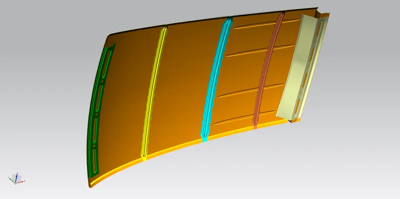
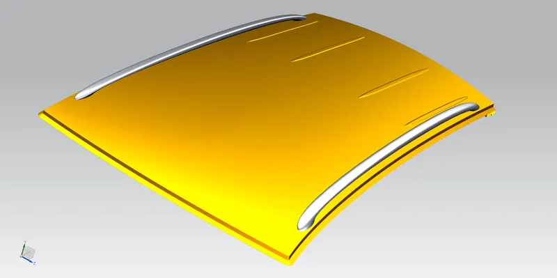
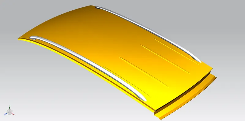
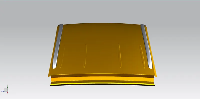
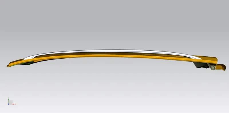
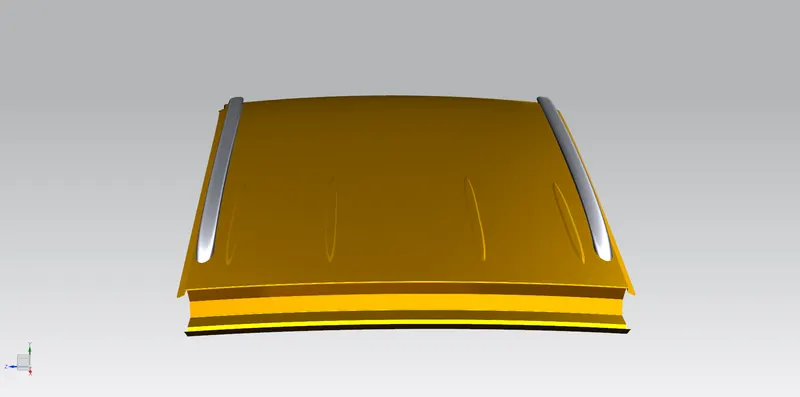
For the Given Roof styling, create an ASSEMBLY by developing the essential flanges for the outer roof and creating the reinforcements.
Introduction:
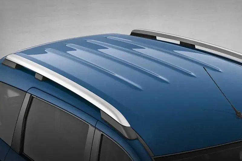
An automobile roof or car top is the portion of an automobile that sits above the passenger compartment, protecting the vehicle occupants from sun, wind, rain, and other external elements. Because the earliest automobiles were designed in an era of horse-drawn carriages, early automobile roofs used similar materials and designs.
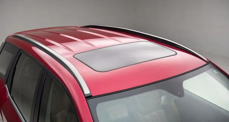
Although it just looks like a styling surface that protects from sun, wind, and other elements and various environmental conditions are considered for designing the same. The roof should be provided with proper reinforcements for strengthening. To make the roof withstand these conditions various calculations are done. This ensures the safety of the passengers in the vehicle. Hence roof plays a crucial role in providing the necessary strength to the car and also protection to the passengers in case of a roll-over crash.
In later years, many variations of the automobile roof have been developed. These include:
1. Convertible roofs
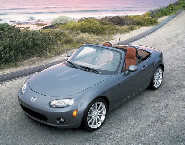
A convertible or cabriolet is a passenger car that can be driven with or without a roof in place. The methods of retracting and storing the roof vary among eras and manufacturers.

A convertible car's design allows an open-air driving experience, with the ability to provide a roof when required. A potential drawback of convertibles is their reduced structural rigidity (requiring significant engineering and modification to counteract the effects of removing a car's roof).
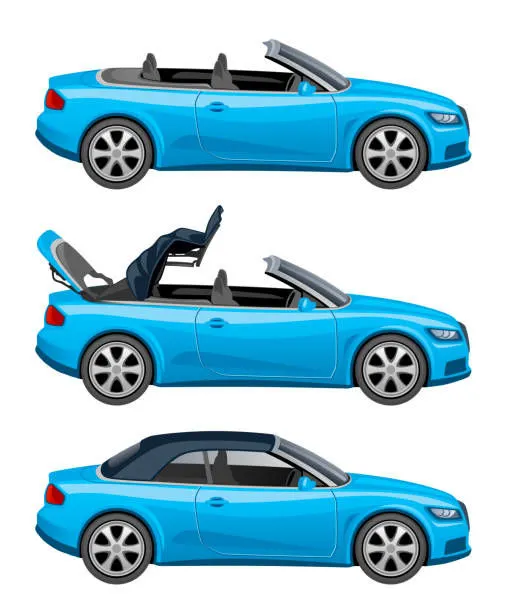
The majority of convertible roofs are of a folding construction framework with the actual top made from cloth or other fabric. Other types of convertible roofs include retractable hardtops (often constructed from metal or plastic) and detachable hardtops (where a metal or plastic roof is manually removed and often stored in the trunk).
2. Hardtops
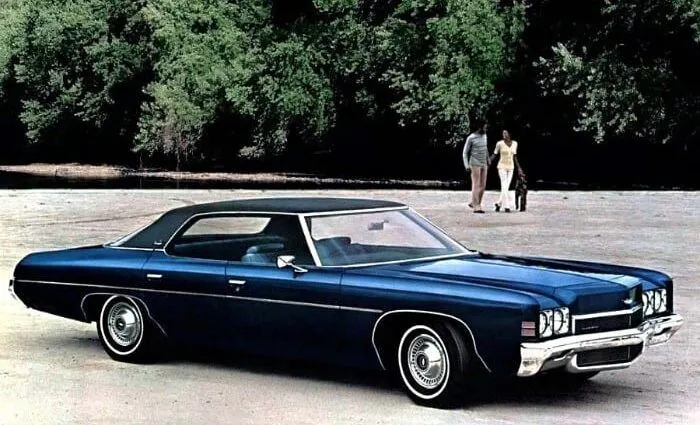
A hardtop is a rigid form of automobile roof, which for modern cars is typically constructed from metal. A hardtop roof can be either fixed (i.e. not removable), detachable for separate storing, or retractable within the vehicle itself.
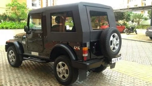
The pillarless hardtop (often referred to as simply "hardtop") is a body style of cars without a B-pillar, which is often styled to give the appearance of a convertible design.
3. Sunroofs
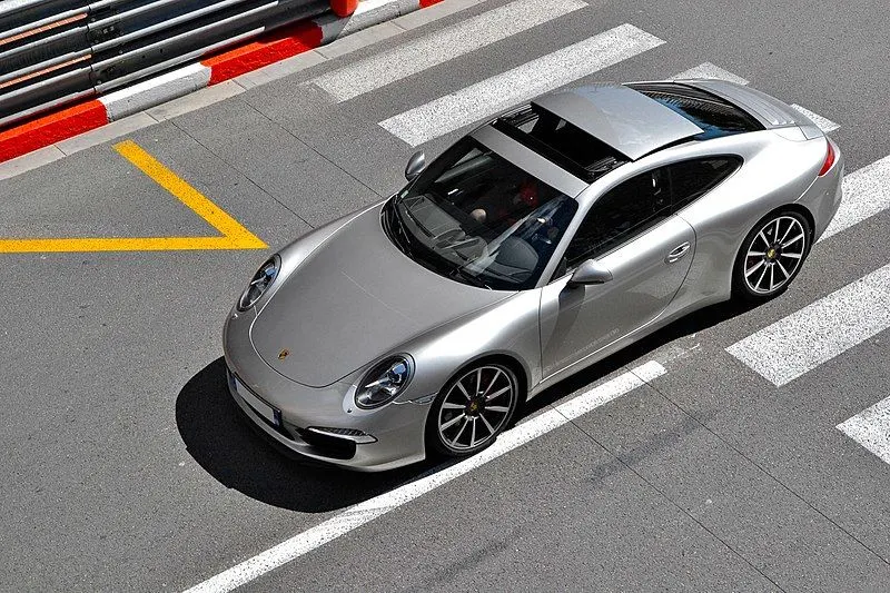
A sunroof is a movable panel that opens to uncover a window in an automobile roof, allowing light and fresh air to enter the passenger compartment.
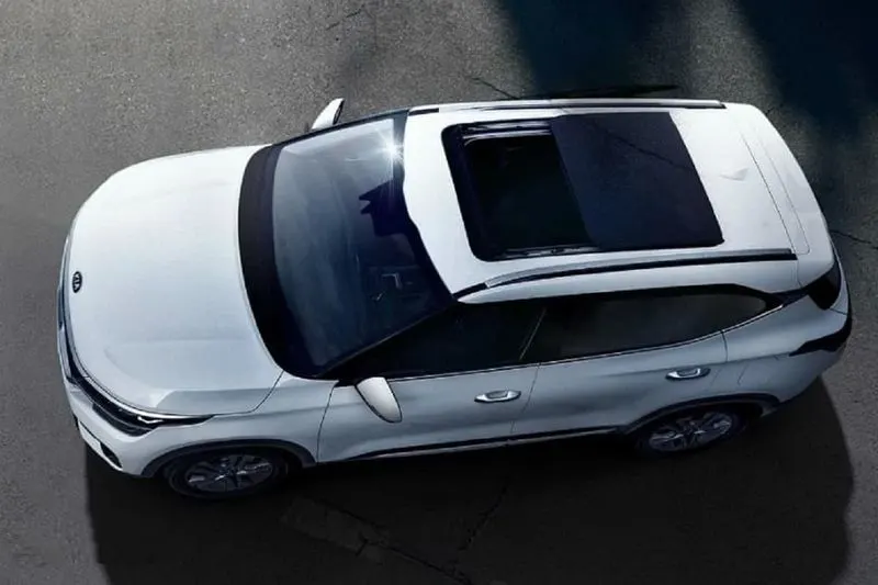
Sunroofs can be manually operated or motor driven, and are available in many shapes, sizes, and styles. While the term "sunroof" is now used generically to describe any glass panel on the roof, the term "moonroof" was historically used to describe stationary glass panes rigidly mounted in the roof panel over the passenger compartment.
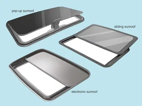
A moonroof has a glass panel that is transparent and usually tinted. Previous terms include Sunshine Roof, Sliding Head, and Sliding Roof.
4. T-tops
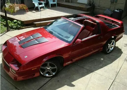
A T-top (UK: T-bar) is an automobile roof with a removable panel on each side of a rigid bar running from the center of one structural bar between pillars to the center of the next structural bar. The panels of a traditional T-top are usually made of auto-grade safety glass.
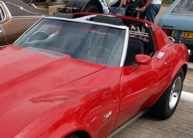
The removable panel roof was patented by Gordon Buehrig on June 5, 1951. It was first used in a 1948 prototype by The American Sportscar Company or “Tasco.”
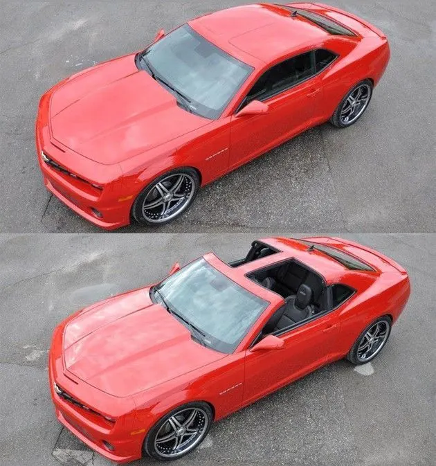
The 1968 Chevrolet Corvette coupe was the first U.S.-built production automobile to feature a T-top roof.[3] This increased the popularity of the coupe, such that it outsold the convertible, and later led to the discontinuation of the Corvette convertible after 1975 until it was revived in 1986.[citation needed] Post-C3 models were built with a Targa top instead of a T-top.
5. Targa tops
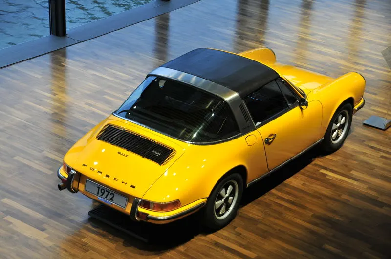
Targa top, or Targa for short, is a semi-convertible car body style with a removable roof section and a full-width roll bar behind the seats. The term was first used on the 1966 Porsche 911 Targa, and it remains a registered trademark of Porsche AG.
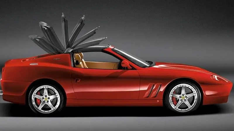
The rear window is normally fixed, but on some Targa models, it is a removable plastic foldable window, making it a convertible-type vehicle. Any piece of normally fixed metal or trim that rises up from one side, over the roof, and down the other side is sometimes called a Targa band, Targa bar, or a wrap-over band.
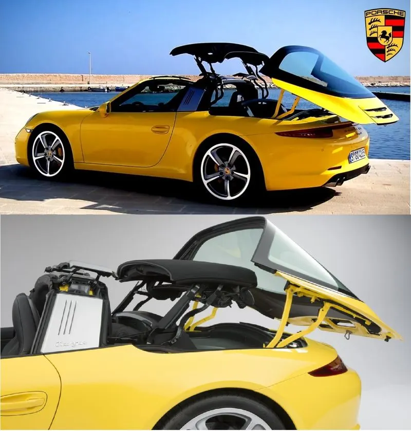
Targa tops are different from T-tops, which have a solid, non-removable bar running between the top of the windscreen and the rear roll-bar, and generally have two separate roof panels above the seats that fit between the window and central t-bar.
6. Vinyl roofs
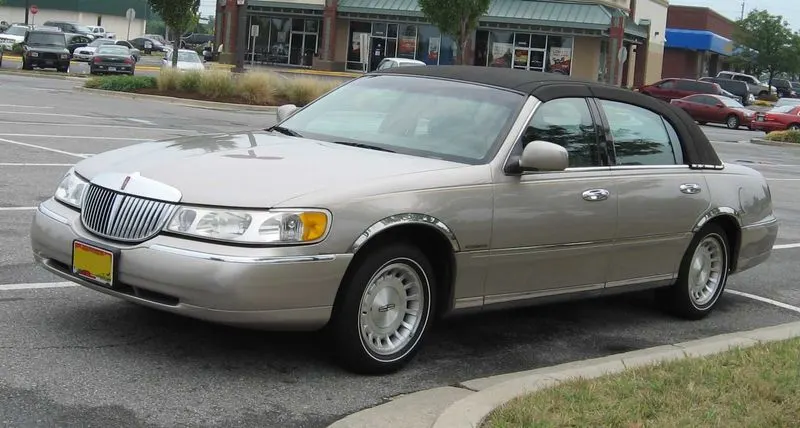
This covering was originally designed to give the appearance of a convertible to models with a fixed roof and eventually evolved into a styling statement in its own right.
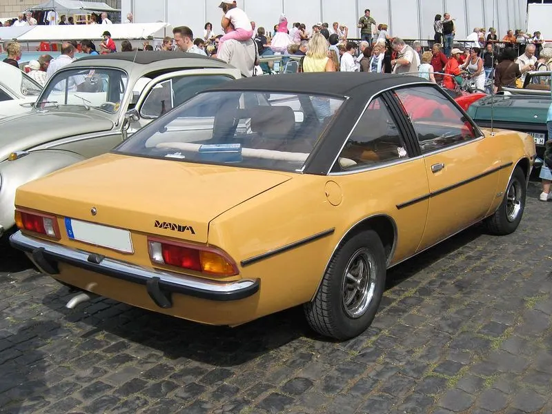
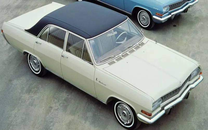
Vinyl roofs were most popular in the American market, and they are considered one of the period hallmarks of the 1970s domestic cars. Vinyl roofs were also popular on European- (especially UK-) and Japanese-built cars during the 1970s, and tended to be applied to sporting or luxury trim versions of standard saloon (sedan) models.
Manufacturing Process:
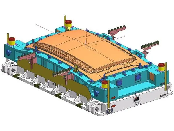
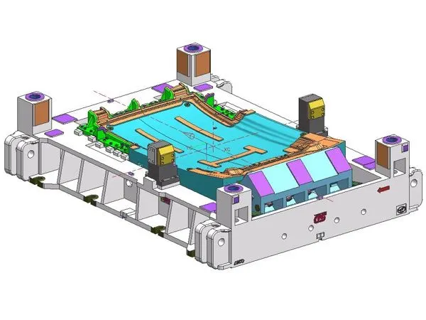
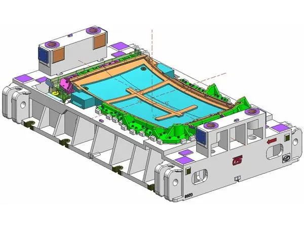
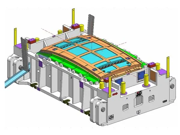
Stamping (Metal Working)
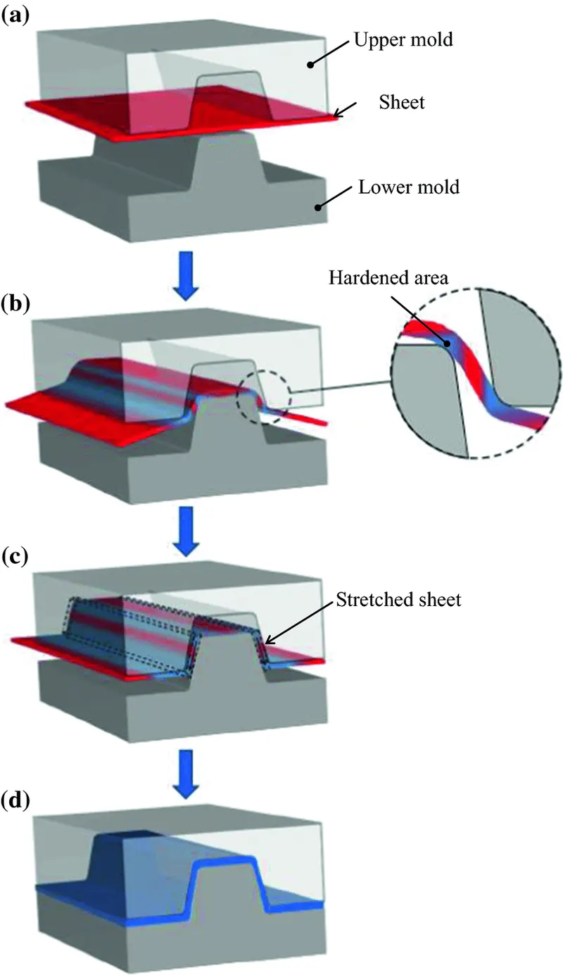
Stamping (also known as pressing) is the process of placing flat sheet metal in either blank or coil form into a stamping press where a tool and die surface form the metal into a net shape. Stamping includes a variety of sheet-metal forming manufacturing processes, such as punching using a machine press or stamping press, blanking, embossing, bending, flanging, and coining. This could be a single-stage operation where every stroke of the press produces the desired form on the sheet metal part, or could occur through a series of stages. The process is usually carried out on sheet metal, but can also be used on other materials, such as polystyrene. Progressive dies are commonly fed from a coil of steel, coil reel for unwinding of the coil to a straightener to level the coil, and then into a feeder which advances the material into the press and die at a predetermined feed length. Depending on part complexity, the number of stations in the die can be determined.
There are three popular types of metal stamping presses used for automotive and other industrial parts. They include:
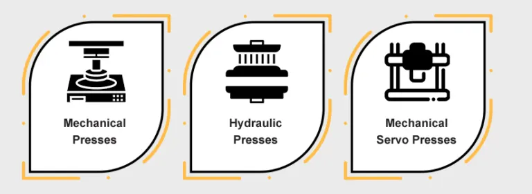
- Mechanical presses - These have a mechanical flywheel powered by a motor.
- Hydraulic presses - These have pressurized fluids that control the pressure and application of force on a workpiece.
- Mechanical servo presses - These use only motors and no mechanical flywheels.
All three press types can work with automated systems, such as automatic feeders, to increase efficiency and production speed. Automatic feeders send coiled or blank sheet metal through the presses to create a fast run.
Main Pressing Operations:
- Bending - The material is deformed or bent along a straight line.
- Flanging - The material is bent along a curved line.
- Embossing - The material is stretched into a shallow depression.
- Blanking - A piece is cut out of a sheet of the material, usually to make a blank for further processing.
- Coining - A pattern is compressed or squeezed into the material.
- Drawing - The surface area of a blank is stretched into an alternate shape via controlled material flow. See also deep drawing.
- Stretching - The surface area of a blank is increased by tension, with no inward movement of the blank edge. Often used to make smooth auto body parts.
- Ironing - The material is squeezed and reduced in thickness along a vertical wall. Used for beverage cans and ammunition cartridge cases.
- Reducing/Necking - Used to gradually reduce the diameter of the open end of a vessel or tube.
- Curling - Deforming material into a tubular profile. Door hinges are a common example.
- Hemming - Folding an edge over onto itself to add thickness. The edges of automobile doors are usually hemmed.
Piercing and cutting can also be performed in stamping presses. Progressive stamping is a combination of the above methods done with a set of dies in a row through which a strip of the material passes one step at a time.
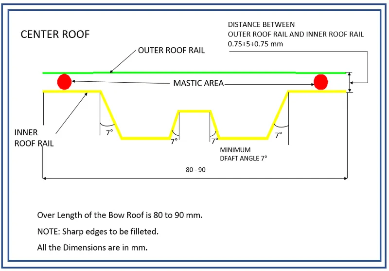
Master Section:
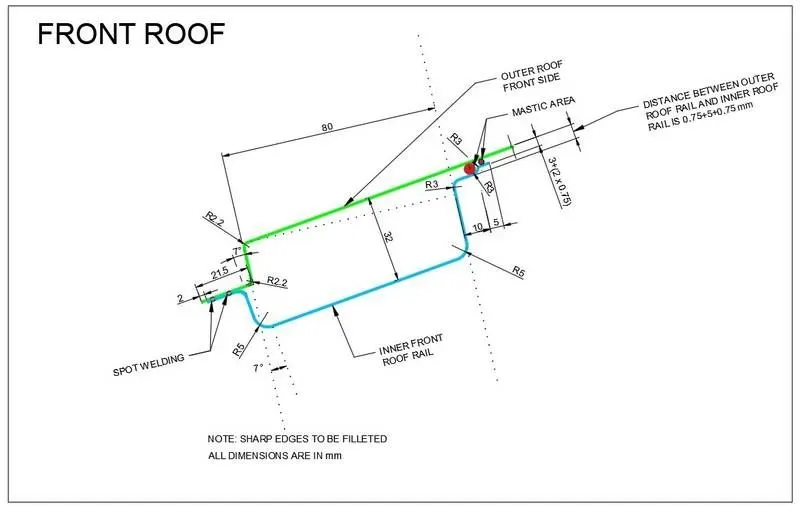
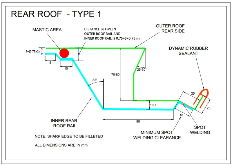
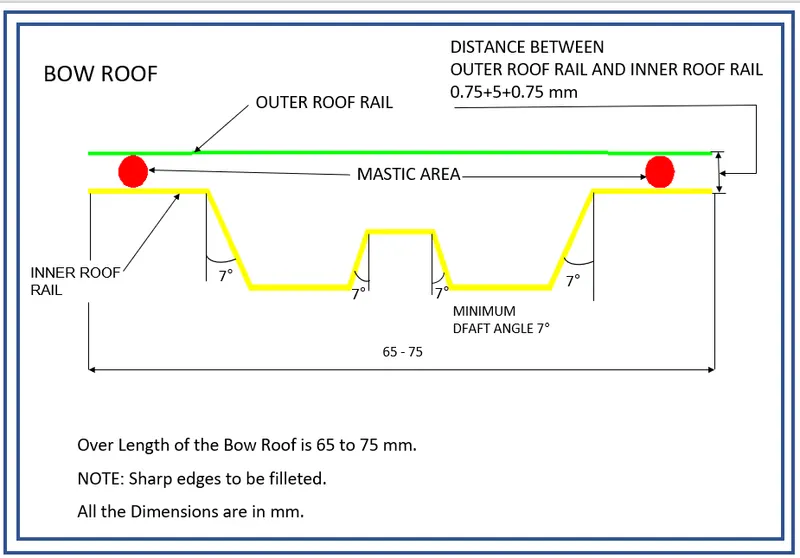
Design Procedure:
Fender Design using NX CAD
Commands Used:
- Datum Plane: This command is used to create a datum plane to construct other features.
- Sketch Commands: Line, Arc, Circle, Rectangle, Point, Fillet, Quick Trim, and Quick Extend.
- Bridge Curve: This command is used to create a tangent blend curve between two objects.
- Offset Curve in Face: This command is used to offset curves along the faces on which they lie.
- Curve on Surface: This command is used to create a surface spline feature directly on a face.
- Law Extension: This command is used to create a law-controlled extension from a base sheet, dynamically or based on laws for distance or angle.
- Face Blend: This command is used to add tangent blend faces between selected sets of faces. The blend shape can be circular, conic, or law controlled.
- Edge blend: This command is used round sharp edges between faces. The radius can be constant or variable.
- Trim Sheet: This command is used to trim off a portion of a sheet body.
- Extend Sheet: This command is used to extend a sheet body by distance or to the intersection with another body.
- Sew: This command is used to combine sheet bodies by sewing common edges together, or combine solid bodies by sewing common faces.
- Thicken: This command is used to a solid body by adding thickness to a set of faces
Design Parameters:
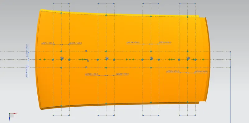
Each section is created according to the Master Section.
Sections are designed in such a way that the roof is thickened in an inward (downward) direction.
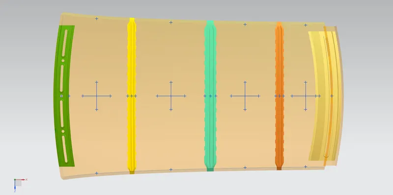
While the Front Roof Rail, Bow Roofs, Center Reinforcement Rail, and Rear Roof Rail are thickened in an outward (upward) direction.
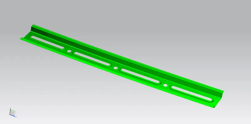
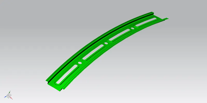
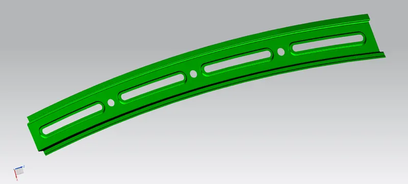
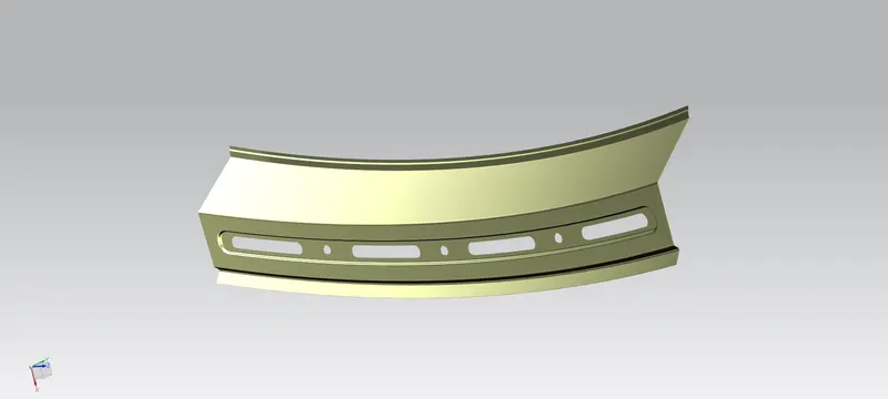
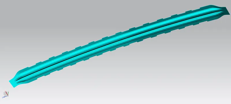
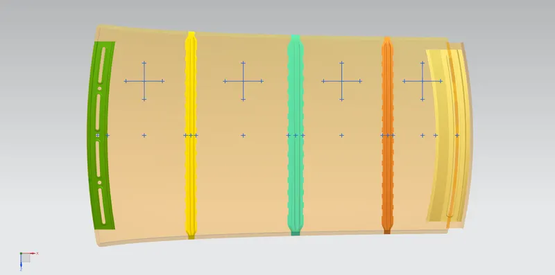
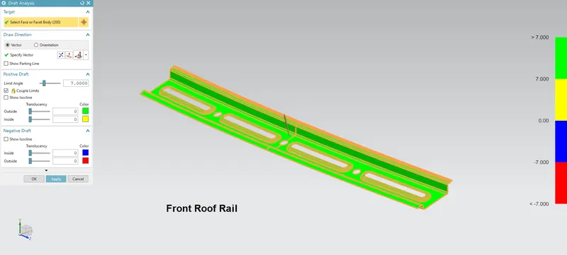
1. Front Roof Rail:
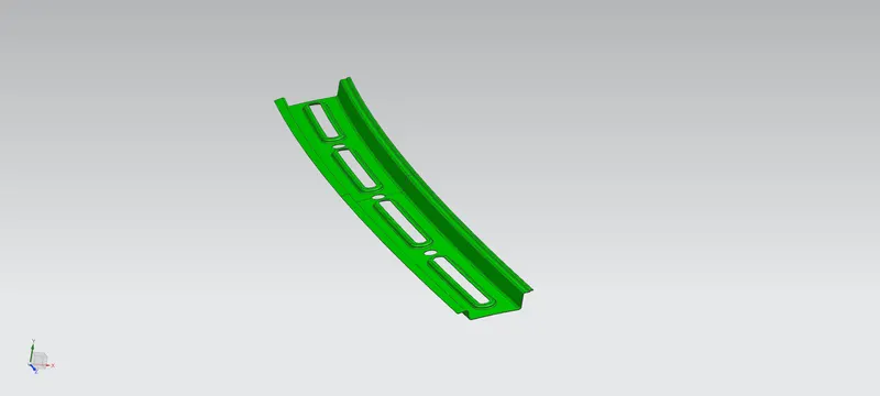
The section is created according to the Master Section.
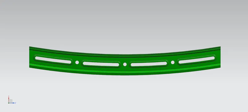
Embosses are provided to increase the local section strength.
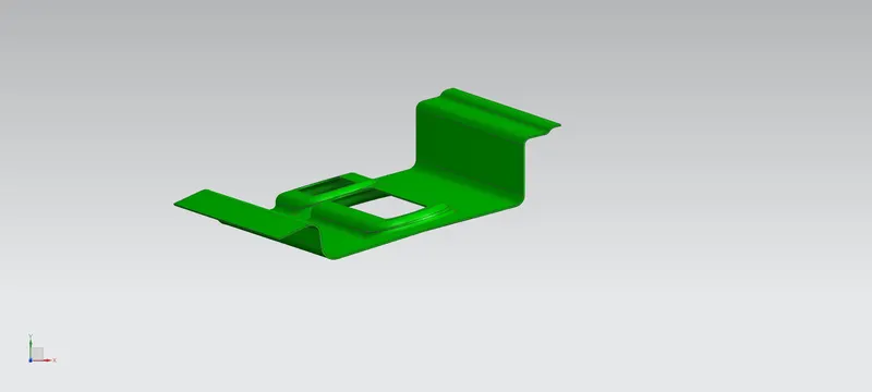
3 mm and 5 mm space is maintained between Front Roof Rail and the Outer Roof as a mastic area.
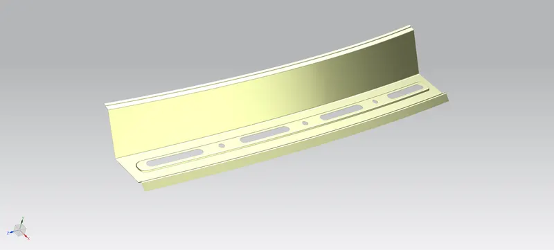
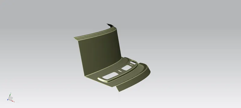
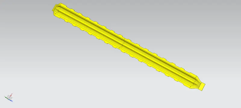
2. Rear Roof Rail:
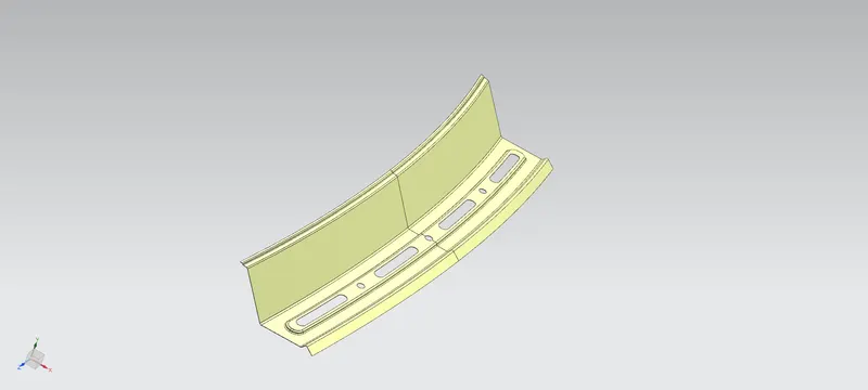
The section is created according to the Master Section.
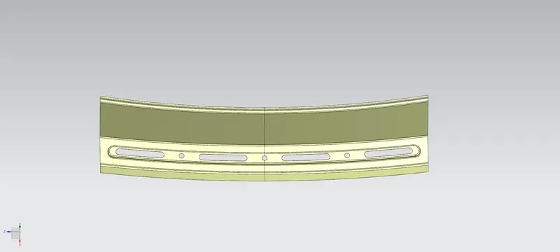
Embosses are provided to increase the local section strength.
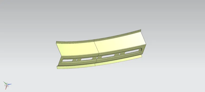
3 mm and 5 mm space is maintained between the Rear Roof Rail and the Outer Roof as a mastic area.
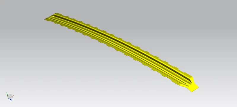
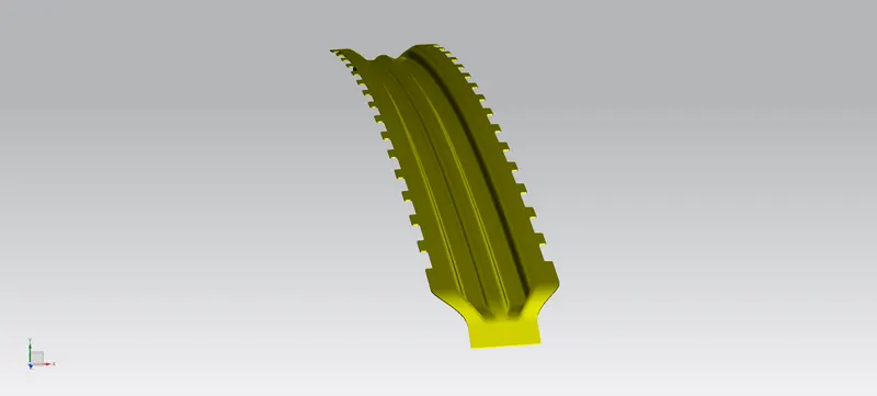
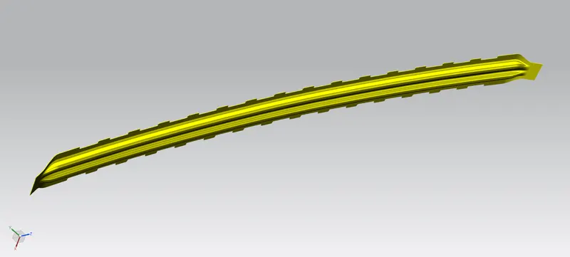
3. Bow Roofs:
Both Bow Roofs 1 and 2 are designed in a similar way.
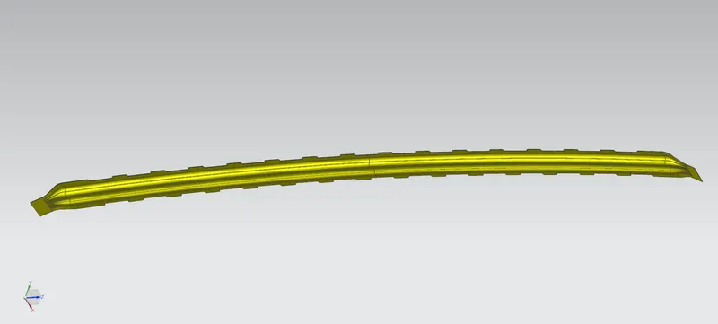
The section is created according to the Master Section.
Mastic sealant areas are provided.
5 mm space is maintained between the Bow Roofs and the Outer Roof as a mastic area.
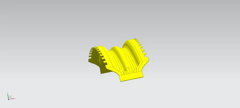
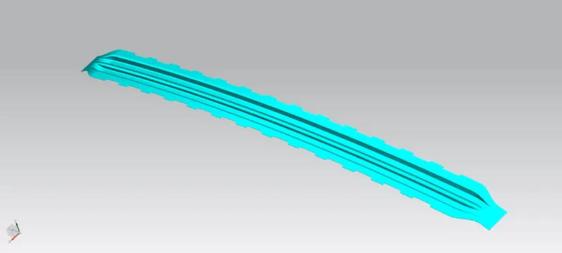
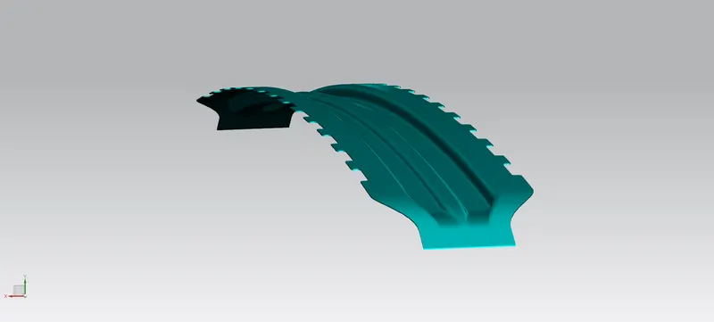
4. Center Reinforcement Rail:
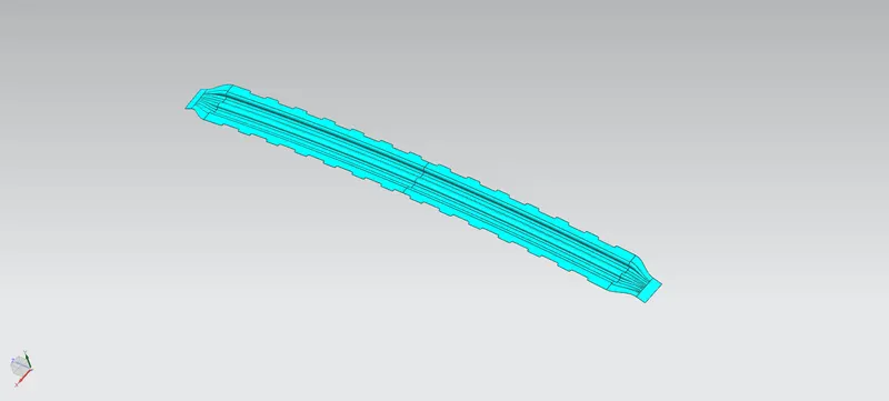
The section is created according to the Master Section.
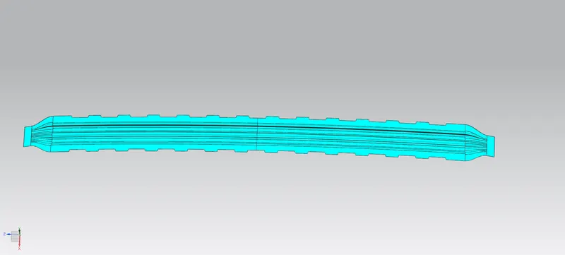
Mastic sealant areas are provided.
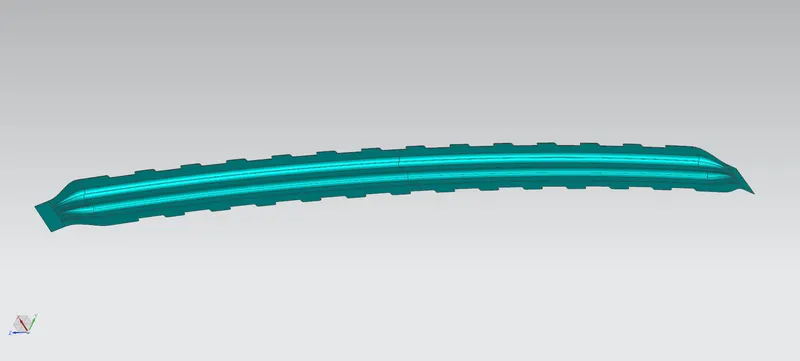
5 mm space is maintained between the Center Reinforcement Rail and the Outer Roof as a mastic area.
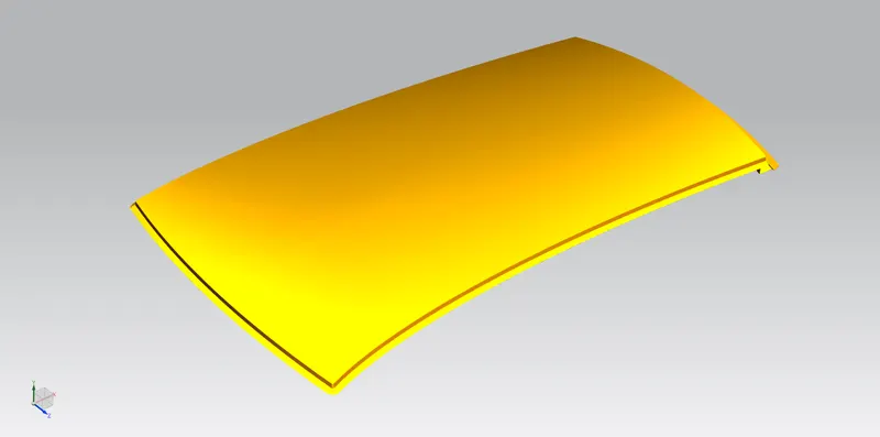
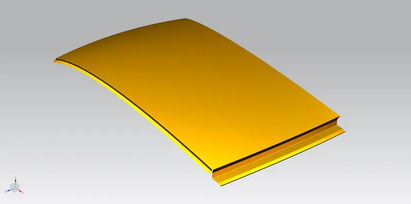
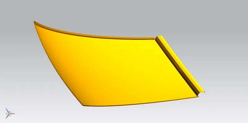
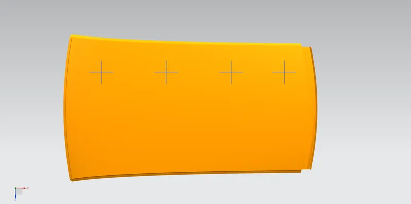
5. Outer Roof:
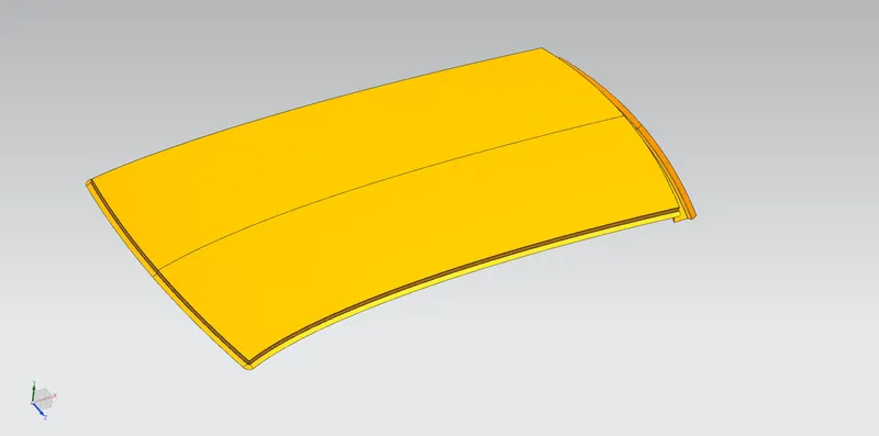
The section is created according to the Master Section.
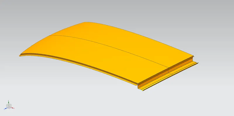
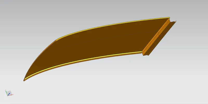
5 mm space is maintained between each rail and the outer roof as a mastic area.
Curvature Study:
1. HEAT DISTORTION:
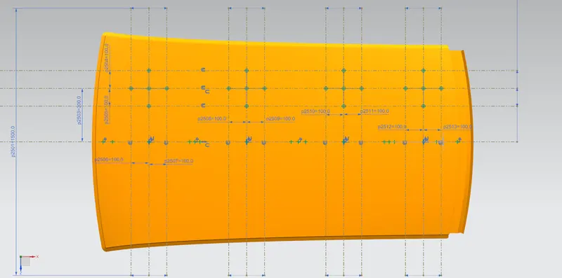
W = [1.73 x 10(-3) x L] + [1.85 x 10(-8) x (R2)/t] + [ 1.10x10(-3) x l] - 2.68
Where,
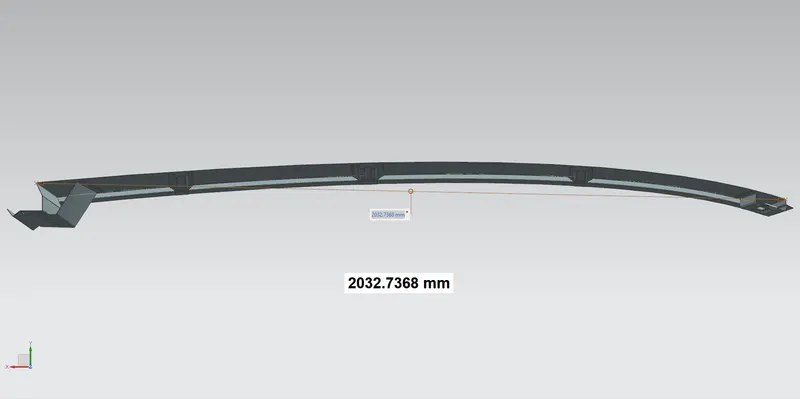
L = Roof Length in X-Direction[mm] (Roof dimension in 0-Y)
R = Roof curvature, R = 2(Rx*Ry)/(Rx+Ry)
Rx = X curvature
Ry = Y curvature
t = Roof plate thickness [mm]
l = Bow Roof Span [mm]
Judgment Condition: OK< 2.7
|
Sr |
Bows |
Rx |
Ry |
R |
l |
L |
t |
(R^2)/t |
W |
OK/NG |
|
1 |
FR – 1st |
5735.5226 |
2610.5397 |
3587.9937 |
435.6755 |
2032.7368 |
0.75 |
17164931.72 |
1.6334 |
OK |
|
2 |
1st - CTR |
4793.5663 |
6915.5308 |
5662.2735 |
510.3346 |
2032.7368 |
0.75 |
42748454.92 |
2.1888 |
OK |
|
3 |
CTR – 2nd |
3787.6327 |
11572.7164 |
5707.3180 |
440.1244 |
2032.7368 |
0.75 |
43431306.22 |
2.1242 |
OK |
|
4 |
2nd - RR |
3153.2585 |
15439.6455 |
5236.9649 |
236.2359 |
2032.7368 |
0.75 |
36567735.15 |
1.7729 |
OK |
As all the values are within the required range, the design satisfies heat distortion criteria. Hence, the design has passed the heat distortion test.
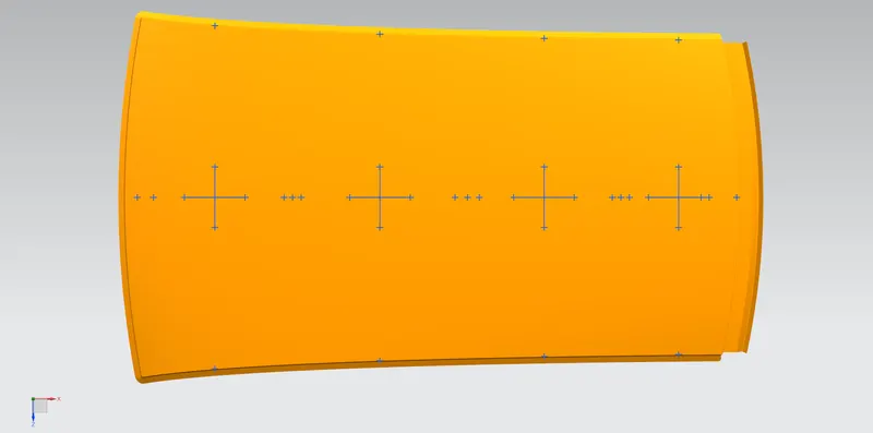
2. SNOW LOAD:
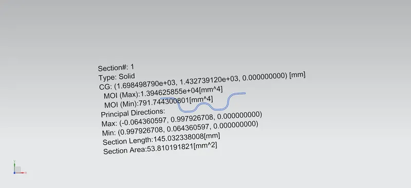
Qr = [Iy x t2] / [α x s x [(Rx + Ry)/2]2 x 10(-8)]
Where,
α = My x Lx2 x 10-12, My = Y(Ly-Y)
t = Roof plate thickness [mm]
Ly = Distance between the front and rear roof Rails on the Vehicle along with 0Y[mm] (Length of Roof panel with the center point between Roof rail Front /Rear as the front and rear reference point.)
Lx = Distance between the Left and Right end of the roof on the Roof BOW [mm] (The width of the roof panel is exposed on the surface.)
Y = Distance front Front Roof Rail to Roof BOW [mm]
s = Distance for which Roof BOW bears divided load [mm], s = L1/2 + L2/2
Iy = Geometrical moment of inertia of Roof BOW (Y cross-section) [mm4]
Rx = Lateral direction curvature radius of roof panel Y cross-section on Roof BOW [mm] (Roof panel curvature Radius of the Length Lx in Front view)
Ry = Longitudinal Direction curvature radius of the Roof panel X cross-section on Roof BOW [mm] (Roof panel X curvature radius of length s in Side view)
Judgment condition: Qr ≥ 3.1
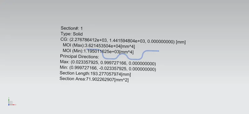
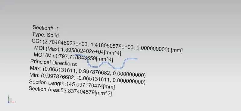
|
Sr |
Bows |
Iy |
α |
Lx |
Ly |
Y |
s |
Rx |
Ry |
t |
Qr |
Determination |
|
1 |
FR – 1st |
791.7443 |
1.0076 |
1135.9739 |
2032.7368 |
514.2007 |
546.1273 |
4489.4905 |
2660.2688 |
0.75 |
6.3329 |
OK |
|
2 |
1st – CTR |
1195.0116 |
0.9818 |
1080.5875 |
2032.7368 |
578.0539 |
542.9038 |
3815.6135 |
6862.6041 |
0.75 |
4.4239 |
OK |
|
3 |
CTR – 2nd |
797.7188 |
0.8598 |
1053.7804 |
2032.7368 |
507.7538 |
445.1770 |
4336.0485 |
12329.9383 |
0.75 |
1.6511 |
NG |
|
4 |
2nd – RR |
- |
0.6851 |
1041.7554 |
2032.7368 |
382.6003 |
- |
3773.3050 |
17618.3164 |
0.75 |
- |
- |
As the 3rd case (CTR – 2nd) failed, the above information is sent to the styling team to change the curvature (Rx/Ry) to achieve a Qr value ≥ 3.1 at that position.
Or
We can provide embosses to strengthen the rear area.
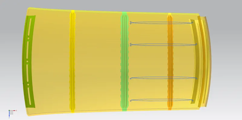
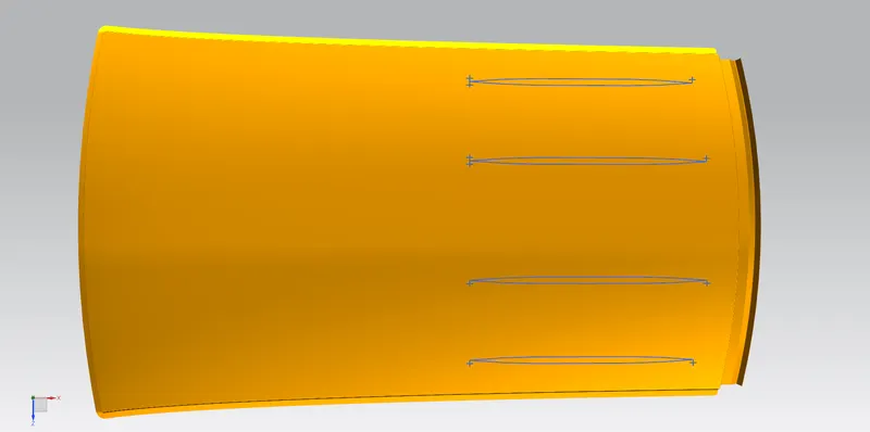
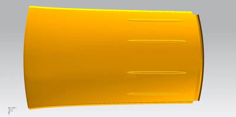
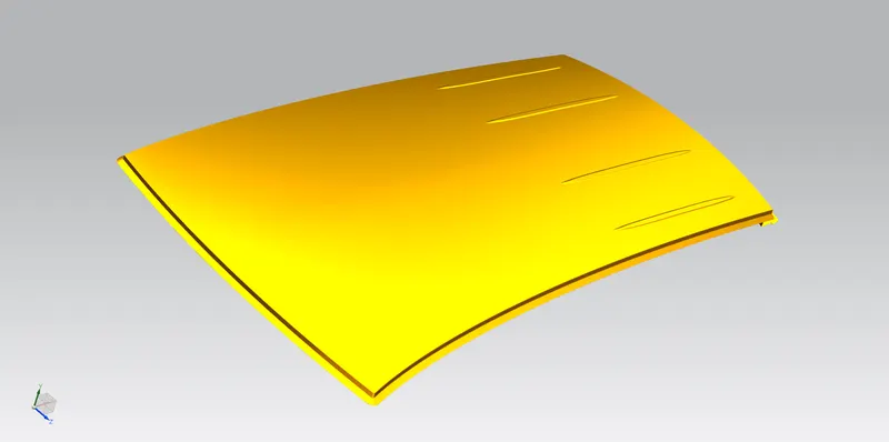
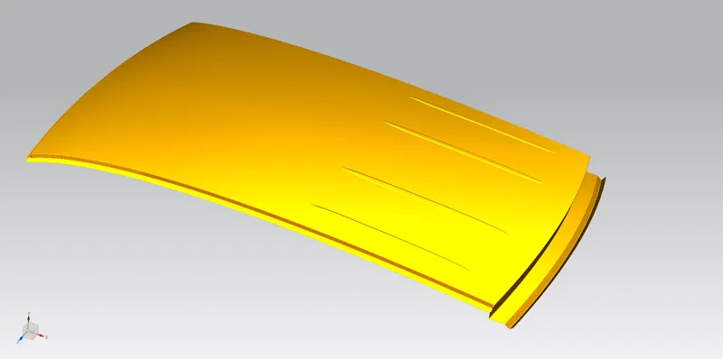
Hence, the outer roof surface is updated.
Final Assembly:
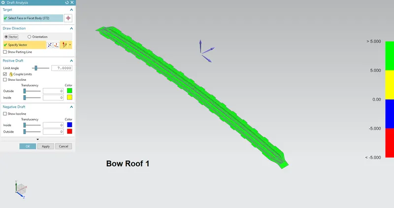
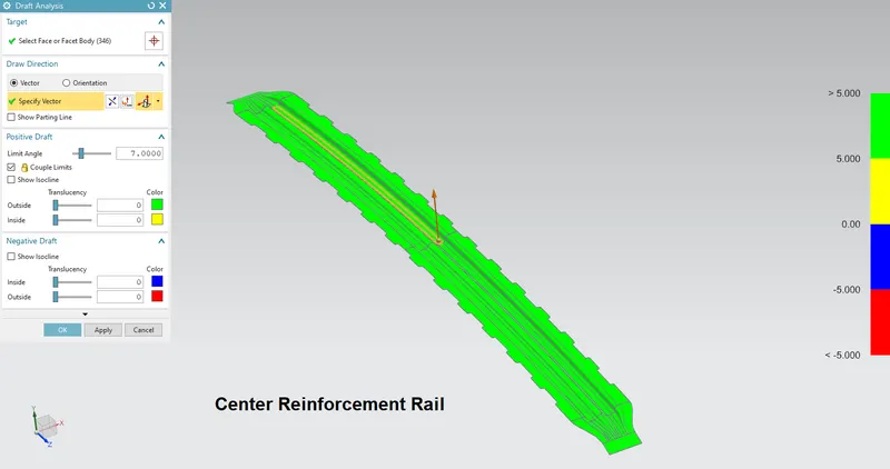
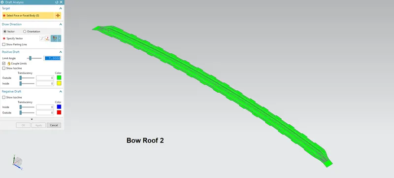
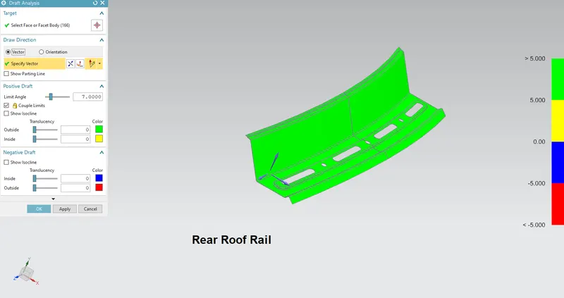
Draft Analysis:
Conclusion:
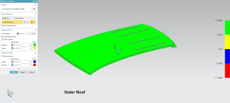
The roof has been designed according to the given master section. Heat distortion and snow load have been calculated.