Hood design-Week 2
Designing of Car Hood
Objective:
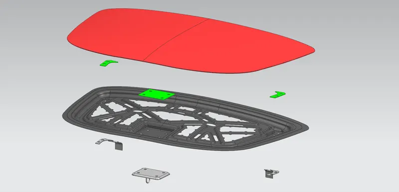
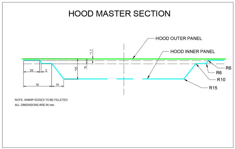
Design Hood Outer Panel, Inner Panel, and the necessary reinforcements by following the Master Section mentioned with the Design parameters.
Introduction:
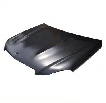
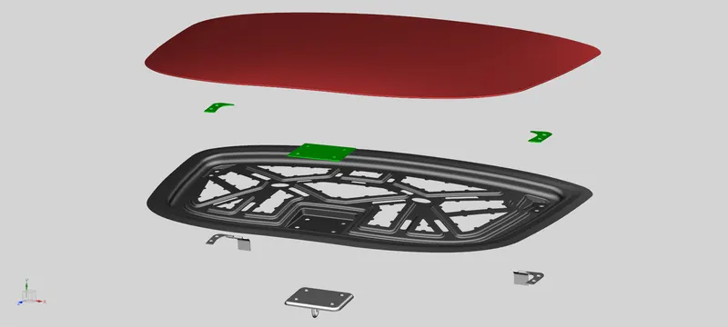
The hood or bonnet is the hinged cover over the engine of motor vehicles. It is an opening body panel that allows access to the engine compartment. Its purpose is to provide access to the engine for repair and maintenance. A concealed latch is typically used to hold down the hood. The outer panel, inner panel, hinges, latch, striker, and other components make up a standard hood. Both outer and inner panels vary in thickness up to 0.75 mm.
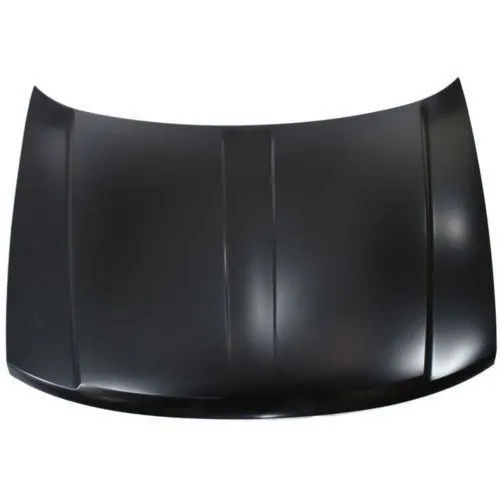
A concealed latch is typically used to hold down the hood. On vehicles with an aftermarket hood and on race cars, hood pins may be used to hold down the car hood. Hoods sometimes also contain a hood scoop, wiper jets, power bulge, and/or hood ornament. Car hoods are typically constructed from steel and sometimes from aluminum. Aftermarket car hoods may be constructed from various other materials, including carbon fiber, fiberglass, or dry carbon.
Data to be used:
Hood Thickness Information:
- Outer Panel Thickness = 0.75mm
- Inner Panel Thickness = 0.75mm
- Reinforcement Thickness = 1.5mm
Master Section:
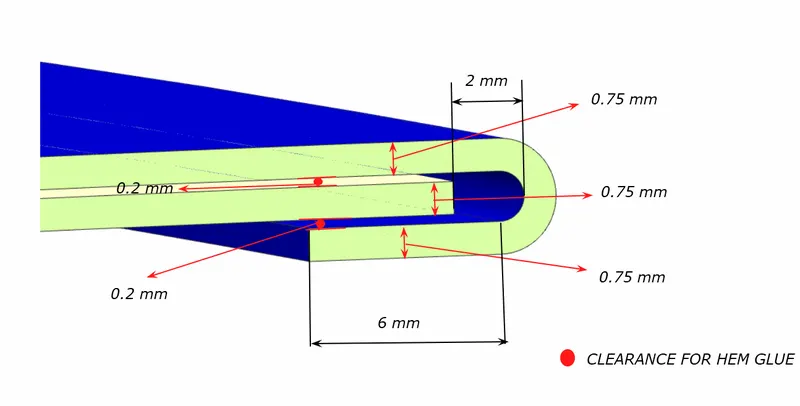
Hemming Data:
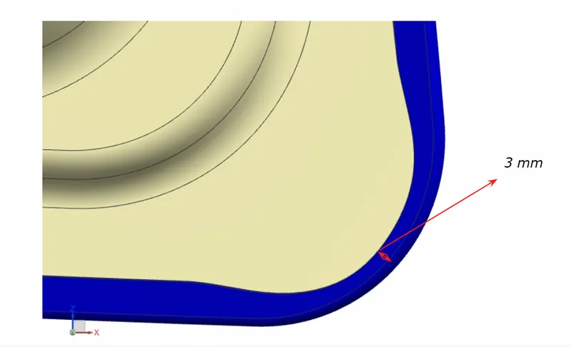
Relief Rear Section:
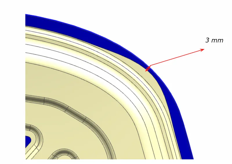
Front Relief:
Parts Files: Skin Data of Hood, Hinge Assembly (Hinge Hood part and Hinge Engine part), and Striker of Hood.
Hood Head Zone:
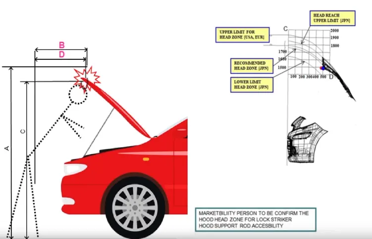
The first thing to consider while designing a hood is the opening angle. The opening angle of the hood is determined by using A, C, B, and D with respect to the ground. The opening angle varies from region to region as it directly depends on the average human weight in that region/country. Depending on the standards we are deciding the angle. From this data, support rods or gas stays are designed.
This is an important consideration since this has to be comfortable enough to open the hood and the striker point of the hood doesn’t hit the human head while working, cleaning, or repairing in a completely open hood position.
Hood Components:
1. Hood Stay:
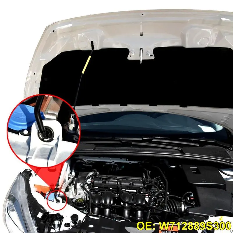
Hood Stay is a component primarily used for the function to put the hood at a fixed opening angle. Hood Stay can be of two types: a support rod or a gas stay type.
Support Rod:
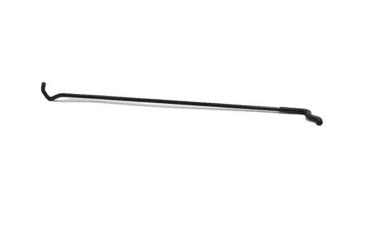
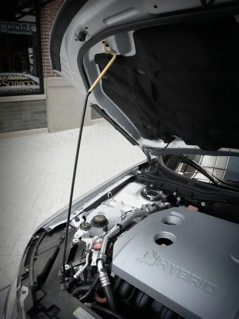
This is a component that acts as a supporting element for the hood in open conditions. The primary function of this component is to keep/hold the hood open at a fixed opening angle. The stick is mounted either mounted on the hood in the engine compartment to support the weight of the hood, making sure it is away/opposite side from the battery or other components while installing the components in open condition. The support rod doesn't have any specific standard design as the shape of the rod depends on the space available in the component and the opening angle. But while designing, it is important to design the rod such that its isn’t strength affected, or else bending may occur due to the heavy weight of the hood which will lead to the bending of the rod. While designing, the x-coordinate of the rod mount and the hook/hole provided for the rod should be the same.

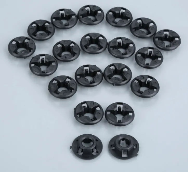
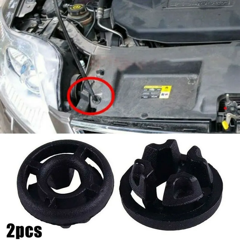
The support rod is fixed using grommets.
Gas Stay:
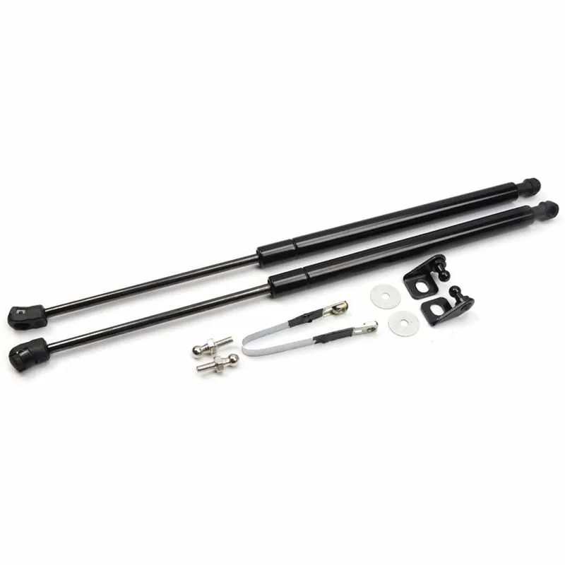
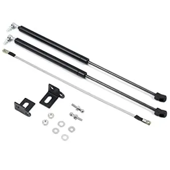
This component acts the same as a support rod as a supporting element for the hood in open conditions. These are usually provided in expensive/luxury cars or cars which have a heavy hood. This a gas-charged cylinders that are used to support the hood of the car while it's open. One of the most common uses of gas stay is in the hood or boot of a car, helping us to comfortably lift and safely close it.
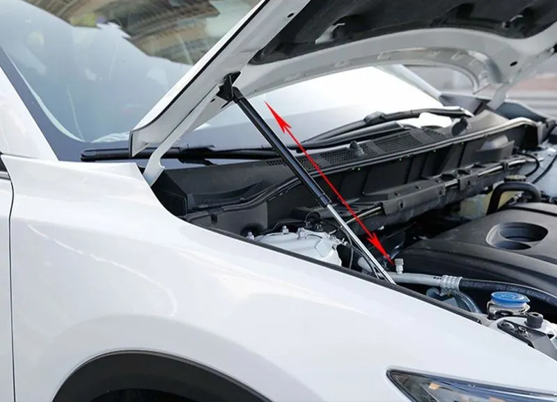
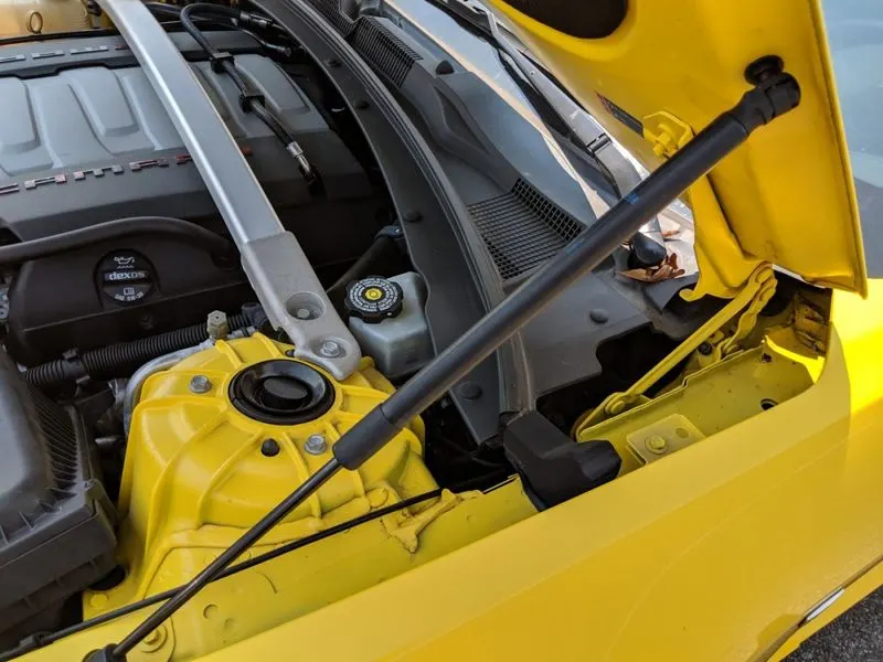
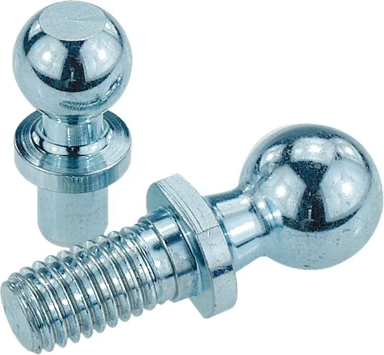
The Gas Stay is fixed using ball studs.
2. Latch and Striker:
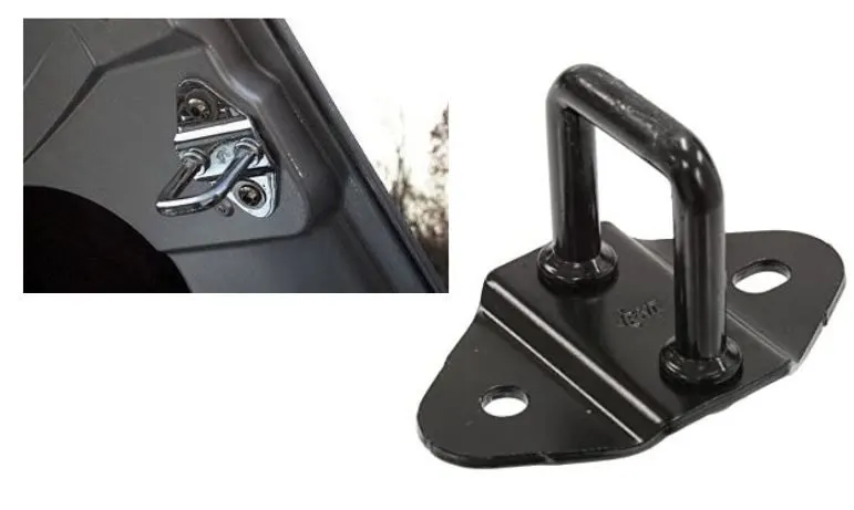
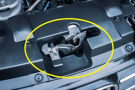
Latch and Striker are a locking mechanism used for locking the hood. Striker is placed in the inner panel and latch in the engine compartment. This mechanism ensures that your hood is securely closed and doesn't open unexpectedly. This locking mechanism engages with the striker in response to the drop of the striker into the vertical slit and locks the striker in a closing position where it holds the engine hood in the closed position.
In general, the hood latch system starts with a release handle located on the right/left side of the driver’s area. This handle is connected to an insulated cable that runs towards the front of the vehicle. The other side of the cable is connected to a latch under the hood that keeps the hood flush against the car’s body. Pulling the interior release handle will disengage the latch and open the hood a few inches. Once the latch has been disengaged, and the hood lifts a few inches, a safety latch will stop the hood from being fully raised.
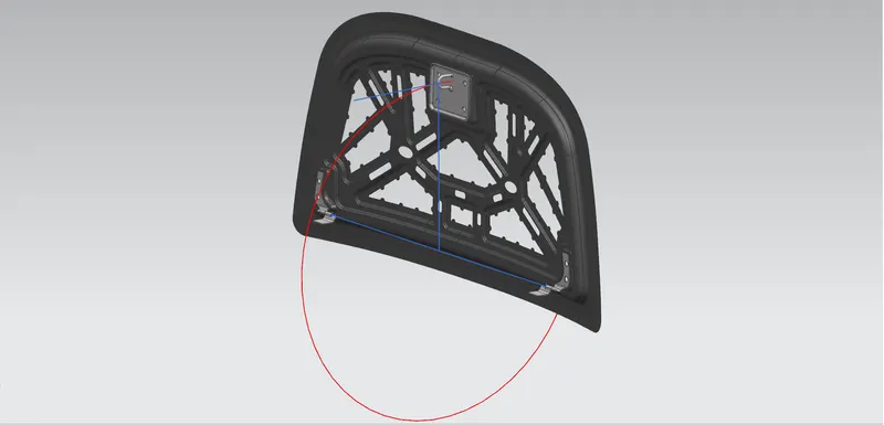
The striker and latch placements are determined by the hood opening/closing trajectory. The striker is placed by keeping the striper point perpendicular to this trajectory with respect to the latch situated in the engine compartment. It is necessary to maintain the perpendicularity for proper closing of the hood with the engine compartment. To do that, we will draw a circle that represents the hood trajectory from the hinge axis point. Then adjust the hinge axis and striker point to get a perpendicular relation.
3. Hinge:
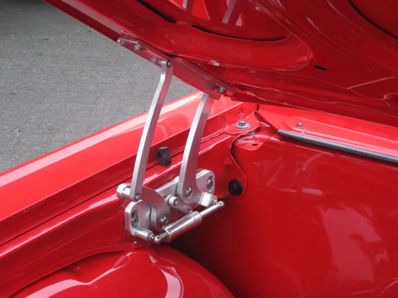
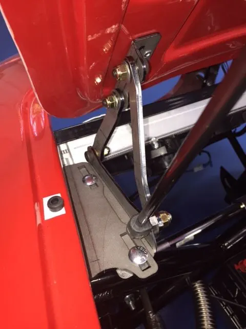
The hinge is a mechanism used to pivot the hood on an axis to open or close the hood. The hood hinge is a mechanism that makes it possible to open and close your hood. The hinge is mounted on the hood and on the engine compartment. The hinge axis is used to determine the trajectory of the striker.
4. Reinforcements:
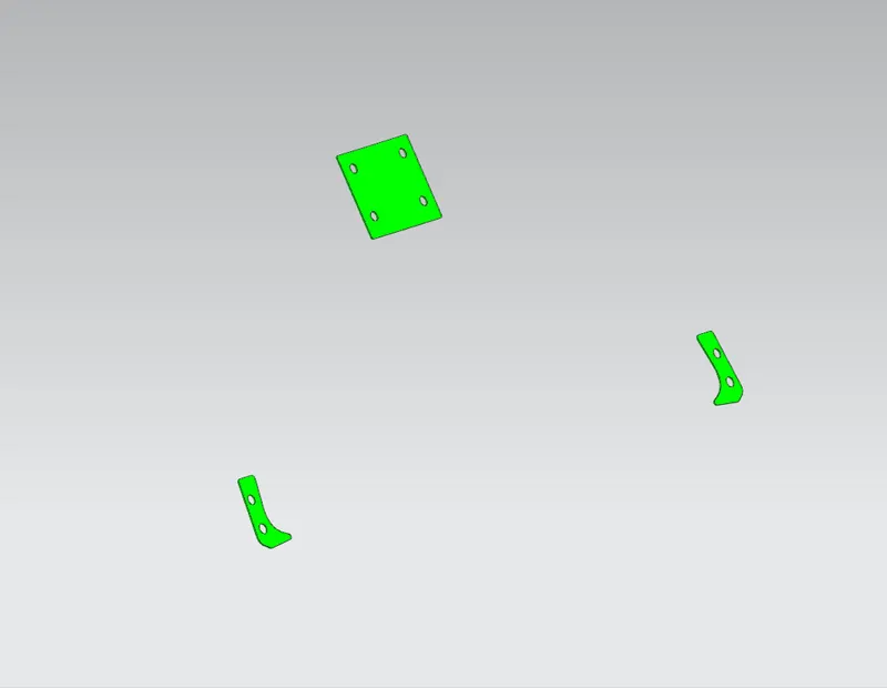
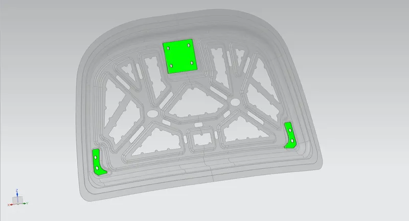
Reinforcements are provided in the hinge and striker position/area to compensate for the strength in those areas.
The given design requirement of reinforcement is 1.5 mm.
NVH:
Noise, vibration, and harshness (NVH), also known as noise and vibration (N&V), is the study and modification of the noise and vibration characteristics of vehicles, particularly cars and trucks. While noise and vibration can be readily measured, harshness is a subjective quality and is measured either via jury evaluations or with analytical tools that can provide results reflecting human subjective impressions. The latter tools belong to the field of psychoacoustics.
Interior NVH deals with noise and vibration experienced by the occupants of the cabin, while exterior NVH is largely concerned with the noise radiated by the vehicle, and includes drive-by noise testing.
The sources of noise in a vehicle can be classified as:
- Aerodynamic (e.g., wind, cooling fans of HVAC).
- Mechanical (e.g., engine, driveline, tire contact patch and road surface, brakes).
- Electrical (e.g., electromagnetically induced acoustic noise and vibration coming from electrical actuators, alternators, or traction motor in electrical cars).
Many problems are generated as either vibration or noise, transmitted via a variety of paths, and then radiated acoustically into the cabin. These are classified as "structure-borne" noise. Others are generated acoustically and propagated by airborne paths. Structure-borne noise is attenuated by isolation, while airborne noise is reduced by absorption or through the use of barrier materials. Vibrations are sensed at the steering wheel, the seat, armrests, or the floor and pedals. Some problems are sensed visually - such as the vibration of the rear-view mirror or header rail on open-topped cars.
There are a few ways to improve NVH:
- Reducing the source strength, as in making a noise source quieter with a muffler, or improving the balance of a rotating mechanism.
- Interrupting the noise or vibration path, with barriers (for noise) or isolators (for vibration).
- Absorption of the noise or vibration energy, for example with foam noise absorbers, or tuned vibration dampers.
- Deciding which of these (or what combination) to use in solving a particular problem is one of the challenges facing the NVH engineer.
Specific methods for improving NVH include the use of tuned mass dampers, subframes, balancing, modifying the stiffness or mass of structures, retuning exhausts and intakes, modifying the characteristics of elastomeric isolators, adding sound deadening or absorbing materials, or using active noise control. In some circumstances, substantial changes in vehicle architecture may be the only way to cure some problems cost-effectively.
Mastic Sealant:
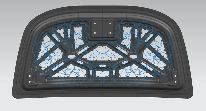
These are the spots where the inner panel and the outer panel of the hood are joined together. The mastic sealant points have an influence area of 80mm each.
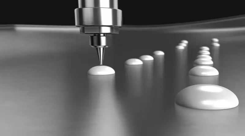
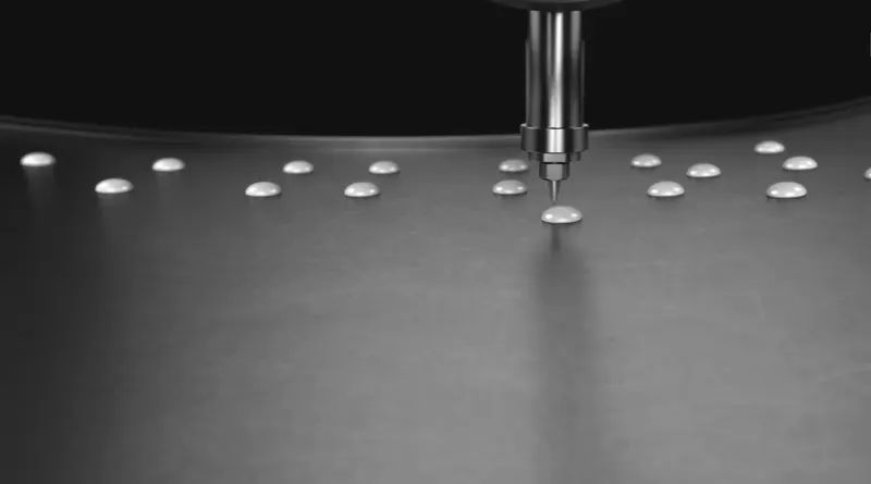
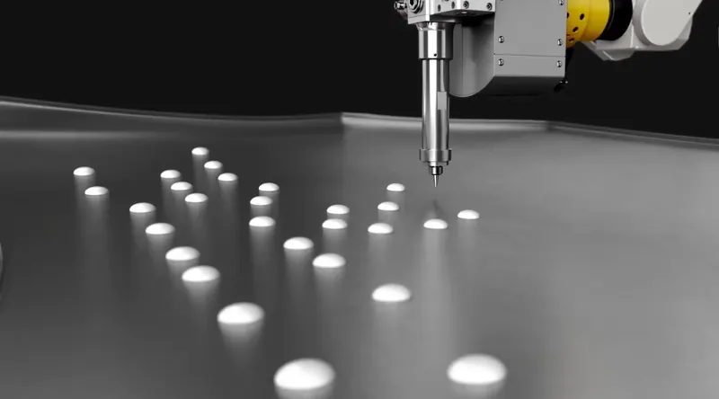
Mastic Sealer is a synthetic rubber-based sealer material that has good filling properties and corrosion resistance. It is designed to apply to doors, roofs, hoods, in specific, the gaps between inner & outer panels. The material is cured through the e-coat oven, and it has the property of paste before the curing processes. Depending on the customer's request, various lap-shear strength and foaming rates would be achievable. These also help in improving NVH.
Manufacturing Process:
1. Embossing:
Sheet metal embossing is a stamping process for producing raised or sunken designs or relief in sheet metal. This process can be made using matched male and female roller dies, or by passing a sheet or a strip of metal between rolls of the desired pattern.
In sheet metal embossing, the deformation of the metal takes place because of stretching of the metal (or tensile force acting on the metal), due to which the sheet metal is subjected to excessive thinning and fracturing.
Thus, the depth to which the material is depressed depends upon the thickness of the sheet as well as the stretchability of the material.
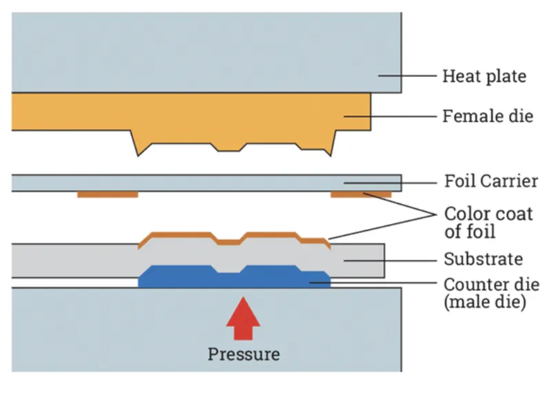
3 things to control during the embossing of sheet metal:
- Pressure: Pressure applied to the sheet metal should be controlled during embossing.
- Heat: Heat level should be maintained consistently during the embossing to get the perfect impressions.
- Die depth: The depth of the die should be adjusted such that the extreme thinning or failure of sheet metal does not occur.
These three factors mostly determine the quality of the embossed product.
During the embossing of sheet metal, the metal sheet is drawn through the male and female roller dies, which ultimately produces a pattern or design on it.
Various types and shapes of dies are used to obtain the desired embossment on the metal sheet.
The combination of pressure and heat is like the principle of ironing the cloth, but here the sheet is depressed instead of straightening.
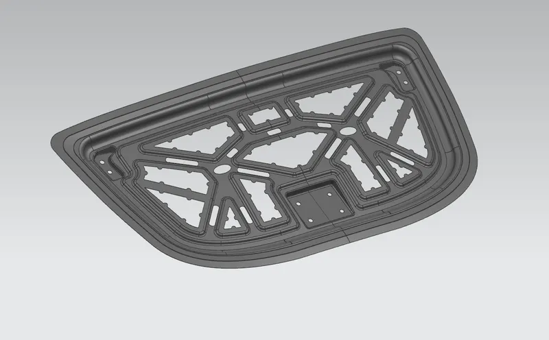
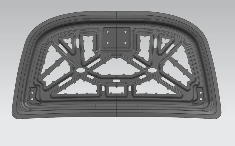
In this design, embosses are provided in the inner panel of the hood assembly. This helps in a weight reduction of the hood as well as to dissipate the force in an outward direction during a collision. They should be designed along the v or y direction for proper force dissipation.
2. Deep drawing:
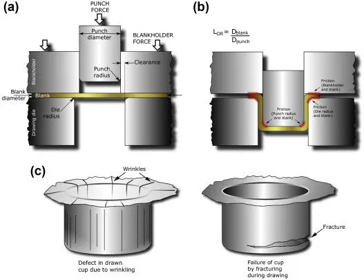
Deep drawing is a sheet metal forming process in which a sheet metal blank is radially drawn into a forming die by the mechanical action of a punch. It is thus a shape transformation process with material retention. The process is considered "deep" drawing when the depth of the drawn part exceeds its diameter. This is achieved by redrawing the part through a series of dies. The flange region (sheet metal in the die shoulder area) experiences a radial drawing stress and tangential compressive stress due to the material retention property. These compressive stresses (hoop stresses) result in flange wrinkles (wrinkles of the first order). Wrinkles can be prevented by using a blank holder, the function of which is to facilitate controlled material flow into the die radius. Deep drawing presses, especially in the Aerospace and Medical industries, require unparalleled accuracy and precision. sheet hydroforming presses for complex draw work. Bed size, tonnage, stroke, speed, and more can be tailored to your specific draw forming application.
The deep drawing process is often a combination of stretch forming and deep drawing. At the beginning of the forming process, when the punch moves downwards and forms out the bottom, a general stretch forming process results. When the bottom is formed, the deep drawing process follows, characterized by the transfer of the drawing force from the punch through the cup wall into the flange. Within the flange results in the main forming process with radial and tangential compression loads.
Typical stages of a deep drawing process are as follows:
- shearing a blank (round rectangular or other shapes).
- clamping the blank on the die.
- stretching the blank by the punch forcing it into the die cavity.
- returning the punch and removing the part from the die.
- trimming the excess blank.
The formability of sheet metal materials through the deep drawing process is affected by various parameters, such as die chamber pressure, die radius, and sheet thickness, all of which directly influence the product's quality.
3. Hemming
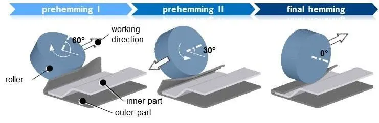
Hemming is a forming operation in which the edges of the sheet are folded or folded over another part in order to achieve a tight fit. Normally hemming operations are used to connect parts together, improve the appearance of a part, and reinforce part edges.
In car part production, hemming is used in assembly as a secondary operation after deep drawing, trimming, and flanging operations to join two sheet metal parts (outer and inner) together. Typical parts for this type of assembly are hoods, doors, trunk lids, and fenders.
The accuracy of the hemming operation is very important since it affects the appearance of the surface and surface quality. Material deformations, which occur during the hemming process, can lead to dimensional variations and other defects in parts. Typical hemming defects are splits or wrinkles in the flange, material overlaps in the corner areas, or material roll-in. This is why it is important to use simulation tools in order to, on the one hand, better understand the hemming process and, on the other hand, significantly reduce the number of “trial and error” loops during tryout and production.
Four Common Types of Sheet Metal Hems:
Closed hem
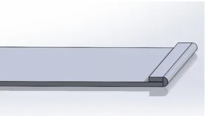
Also known as a crushed hem, a closed hem is completely flush (as opposed to an open hem, which allows for a bit of space in the bend). Closed hems are the most popular type of hem because they’re so easy to make: the sheet metal is simply flattened onto itself. There are, however, some material limitations.
This type of hem works best with material thicknesses of .040”-.125”. We try to avoid forming material over .125” because the sheet metal is likely to fracture. The flat length of the hem must also be a minimum of 4x the material thickness so that it doesn’t break.
We shape our closed hems by forming sheet metal to 145 degrees, then flattening the material onto itself with a press brake. As a rule, we don’t use closed hems for aluminium, as this type of material is highly susceptible to cracks and fractures.
Teardrop hem
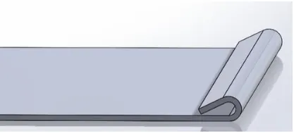
A teardrop hem is a flange that has been bent more than 180 degrees. We use teardrop hems for materials that lack the flexibility required of closed hems. This type of hem is perfect for aluminium and other fragile metals.
Open hem

An open hem features a soft, curved outer edge and an air pocket in its bend. It’s ideal for handles and other applications that come into contact with people. Like a closed hem, an open hem works best with material thicknesses of .040”-.125” and a flat length that’s a minimum of 4x the material thickness. We shape our open hems by forming sheet metal to 145 degrees, then inserting a shim and flattening the material onto itself with the shim in place. Common gap sizes are 060”, .090”, .125”, .187”, and .250”.
Rolled hem
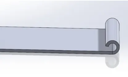
The purpose of a rolled hem is to eliminate raw sheet metal edges from a part. This type of hem is common for door and figure edges. Rolled hems provide a nice clean look and a safe-to-handle part.
Design of Hood Panel to Achieve Better Pedestrian Safety:
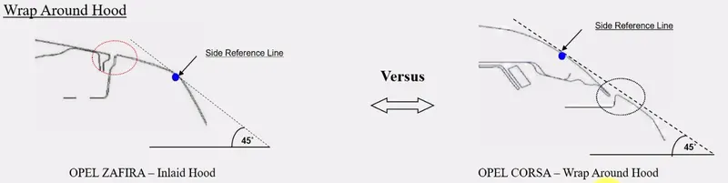
Inlaid Hood: The line which is drawn 45 degrees from the ground as a side reference of the car, meets on the fender is called Inlaid Hood.
Wrap Around Hood: The line which is drawn 45 degrees from the ground as a side reference of the car, meets on the surface of the hood is called Inlaid Hood.
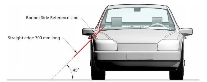
Side Reference Line (SRL): The Bonnet Side Reference Line is defined as the geometric trace of the highest points of contact between a straight edge 700 mm long and the sides of the vehicle, when the straight edge, is held parallel to the transverse vertical plane of the vehicle and inclined inwards by 45°, is traversed down, and maintains contact with the sides of the front structure.
According to NHTSA statistics, despite the total number of traffic fatalities decreasing, more than 6,000 pedestrians die in accidents each year in the United States alone.
In Russia, the number of deaths per 1,000,000 population is 2.5 times higher than the average for European countries. The high death rate is affected by both poor road conditions and using old cars with low-quality pedestrian protection systems. However, certification rules regarding pedestrian protection are being tightened in Russia year by year, approaching European standards.
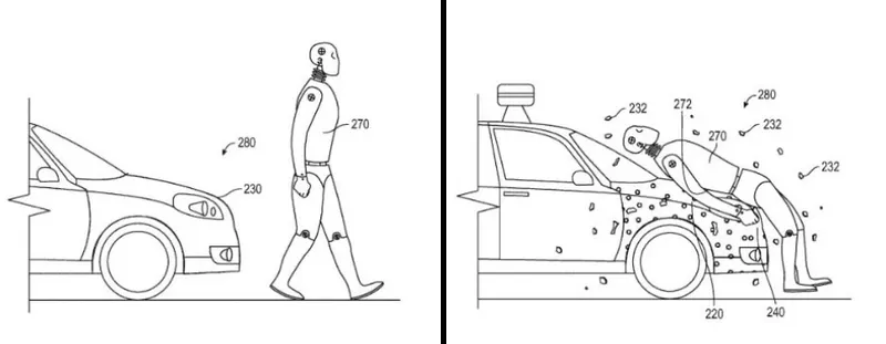
When a car collides with a pedestrian, as a rule, the vehicle bumper first contacts the lower leg and thigh, and then the head hits the hood area. Leg injuries are painful and can lead to long-term disability. However, head injuries are the most dangerous, which are often fatal. Therefore, it is so important to predict and prevent the overloads that a person’s head experiences when hitting a car. The decisive factor determining the degree of head injury is the structure of the hood since it should slow down the head, preventing critical overloads and excluding the possibility of contact of the head with massive elements of the underhood space. The hood structure is tested for pedestrian protection according to the rules of the EuroNCAP rating test. The success of these tests is evaluated using HIC (Head Injury Criteria).
Hence, when a car crashes on a pedestrian, the whole human body wraps around the front shape of the car, and the head impacts the bonnet or the windscreen. The distance at which the head impacts the car from the ground is called the Wrap Around Distance (WAD).
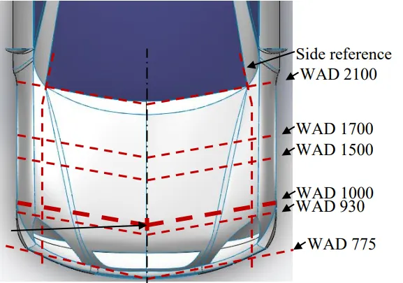
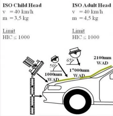
According to the requirements of NCAP for pedestrian protection, it needs to define zones of the car hood for analysis. It can be noted that when the collision projection point locates between (Wrap Around Distance) WAD 1000 and WAD 1500, the head type will use the children's head type. The adult head type will be used while the collision projection point locates between WAD 1700 and WAD 2100.
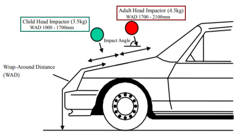
However, the mechanism of injury is complex. The Head Injury Criterion (HIC) indicates a measure of a head injury arising from an impact, which is evaluated by the impactor in terms of the simulation of child's head. HIC includes the effects of head acceleration and the duration of the acceleration.

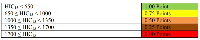
The below table presents the rules for setting EuroNCAP rating points for the hood point where the test took place, depending on the value of the criteria.
Design Procedure:
Hood design using NX CAD
Commands Used:
- Sketch Commands: Line, Arc, Circle, Fillet, Quick Trim, Quick Extend, Make Corner, Offset Curve, Offset Curve in Face, and Project Curve.
- Through curves: This command is used to create a body through multiple sections where the shape changes to pass through each section
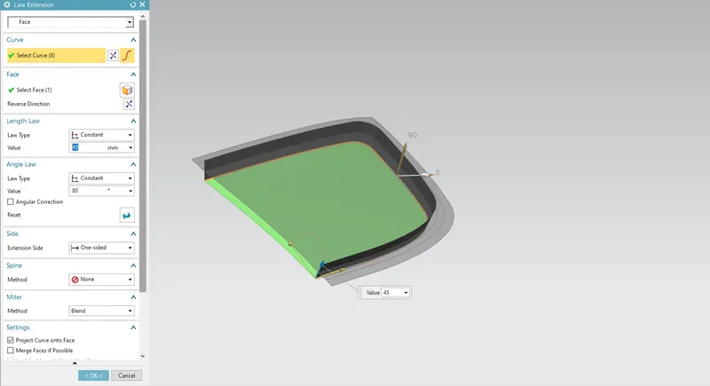
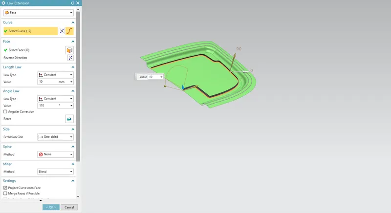
- Law Extension: This command is used to create a law-controlled extension from a base sheet, dynamically or based on laws for distance or angle
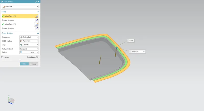
- Face Blend: This command is used to add tangent blend faces between selected sets of faces. The blend shape can be circular, conic, or law controlled
- Edge blend: This command is used round sharp edges between faces. The radius can be constant or variable.
- Offset Surface: This command is used to create a body by offsetting a set of faces.
- Trim Sheet: This command is used to trim off a portion of a sheet body.
- Trim Body: This command is used to trim off a portion of a body.
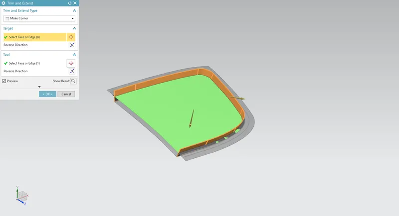
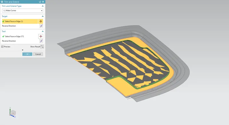
- Trim and Extent: This command is used to trim or extend a set of edges or faces to the intersection with another set of edges or faces.
- Extend Sheet: This command is used to extend a sheet body by distance or to the intersection with another body.
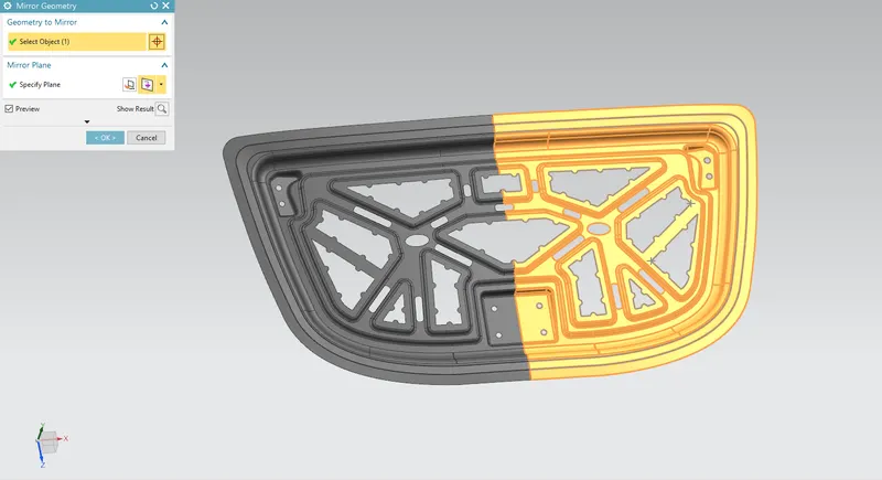
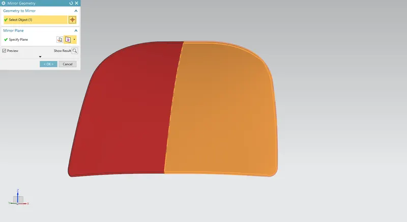
- Mirror Geometry: This command is used to copy geometries and mirror them across a plane
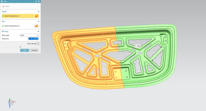
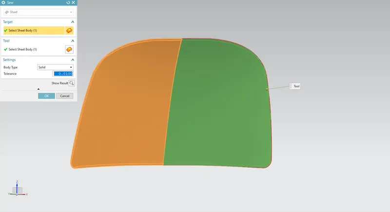
- Sew: This command is used to combine sheet bodies by sewing common edges together, or combine solid bodies by sewing common faces.
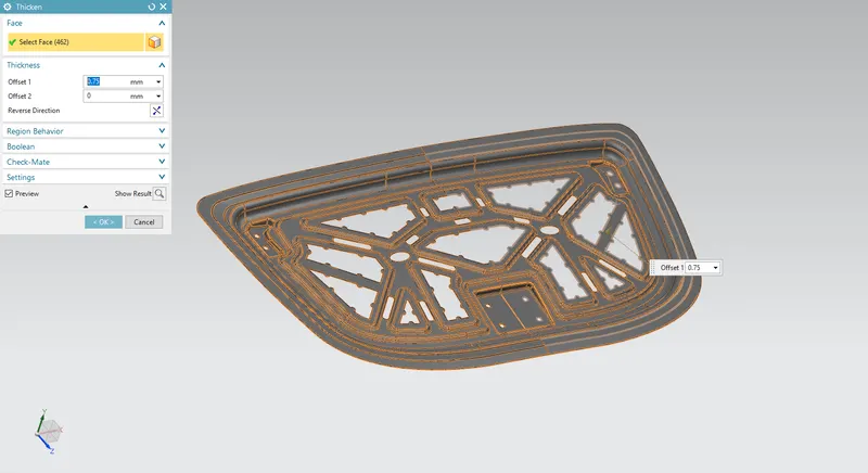
- Thicken: This command is used to a solid body by adding thickness to a set of faces
- Assembly:
- Add: Adds components to the assembly by selecting loaded parts or parts from the disk.
- Create New: Creates a new component in the assembly by selecting geometry and saving it as a component
- Assembly Constraints: Position components in relation to other components in the assembly by specifying the constraint relationship.
- Move Component: Moves a component in the assembly.
- WAVE Geometry Linker: Copies geometry from other parts in the assembly into the work part.
- Mirror Assembly: Create a mirrored version of the entire assembly or of selected components.
Import the file into assembly: New >> Assembly >> Add >> Hood_Outer_Panel >> OK
Create New >> Model >> give the name as Hood_Inner_Panel >> OK
Add >> Open the striker and hinge assembly file from the location >> OK
After the creation of the inner panel, align the striker and hinge to the inner panel properly by providing the necessary constraints. Then, create a mirror of the hinge assembly by Mirror Assembly >> Hinge_Assembly >> Mirror Plane as YZ plane >> Give name >> Select the Associative Mirror option by selecting the hinge assembly >> Next >> OK
Referring to the Master Section/Given Data:
Make sure to give a positive draft in the required regions in the outer and inner. Hence, certain draft angles are given in each required section. Following all the design requirements and designing the part according to the Master Section/given data.
To create the Inner Panel:
Create a 0 mm offset of the outer panel to use it as a working surface and trim the surface into half w.r.t YZ plane.
Create a 1.7 mm offset of the outer panel to create the first layer of the inner panel layer.
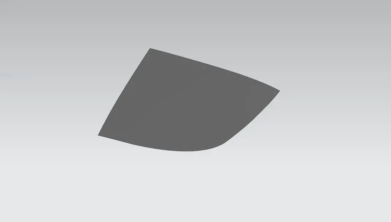
Create an offset on the face of 20 mm and trim it.
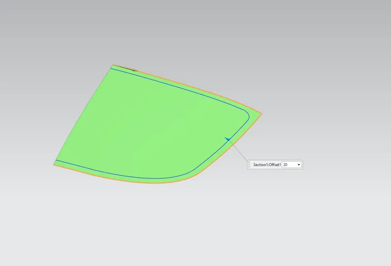
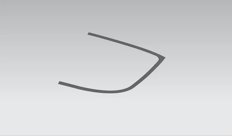
Create a 4 mm offset of the outer panel to create the second layer of the inner panel layer.
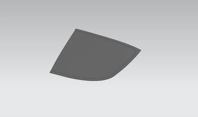
Create an offset on the face of 35 mm and trim it.
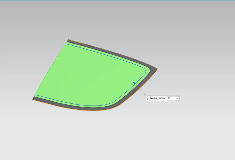
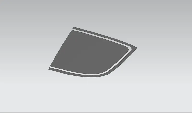
Use Through Curves to create a surface body between the two created surfaces.
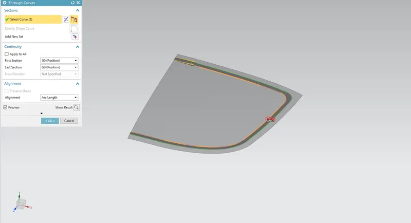
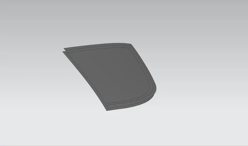
Create a 25 mm offset of the outer panel to create a third layer of the inner panel layer.
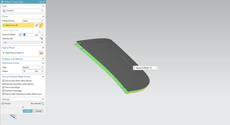
Create an offset on the face of 50 mm and trim it.
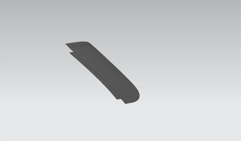
Use Law Extension to create a law.
Use Trim and Extend to remove the unnecessary surface.
Now add face blend and edge blend between the created surfaces.
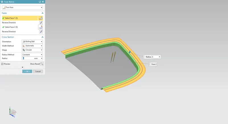
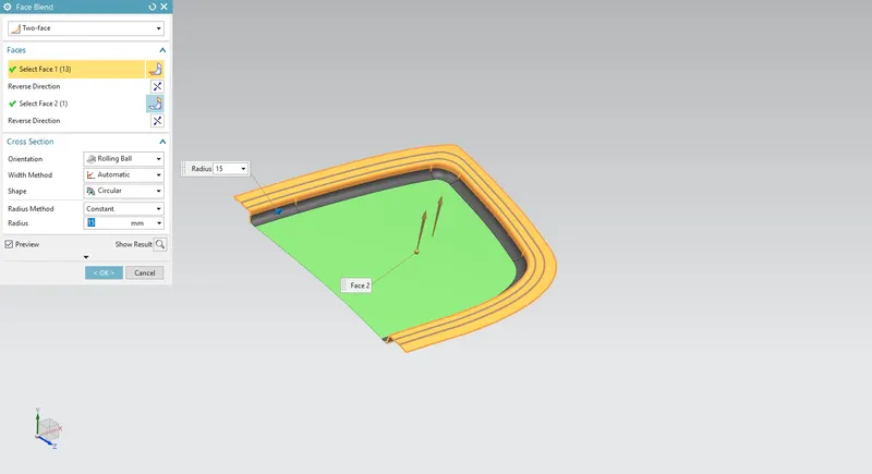
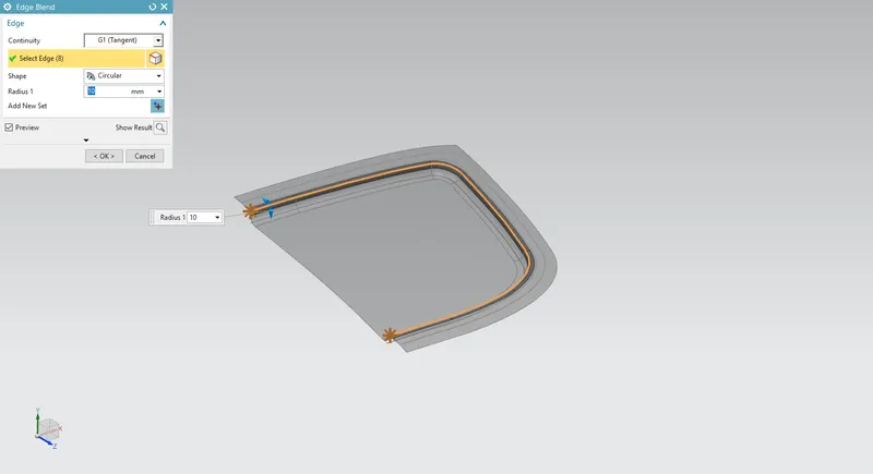
Create the sketch by taking a raw estimation of the location of the striker and hinge, then project it on the surface.
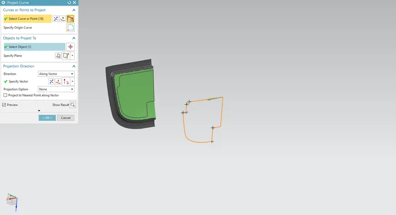
Create a law extension using this sketch.
Offset the surface to 5 mm and trim it.
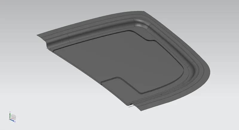
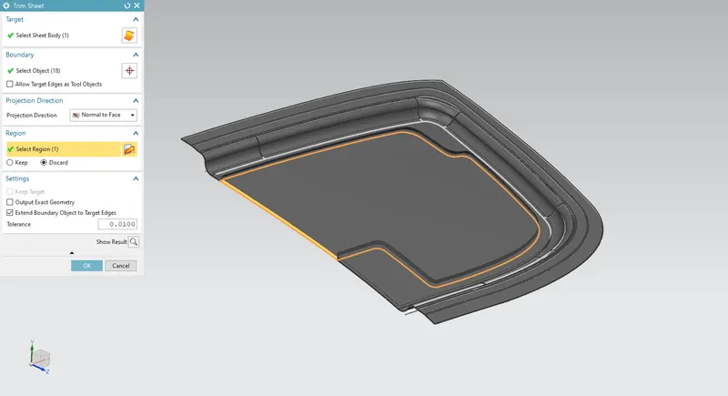
Use Trim and Extend to remove the unnecessary surface.
Create the sketch and project it on the surface.
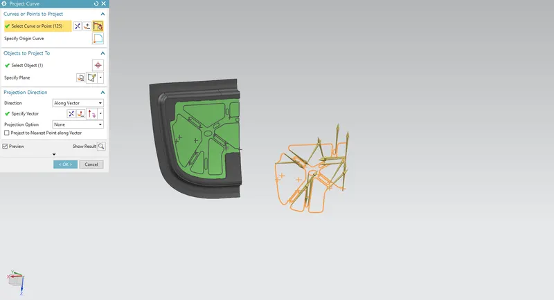
Create embosses using this projected sketch.
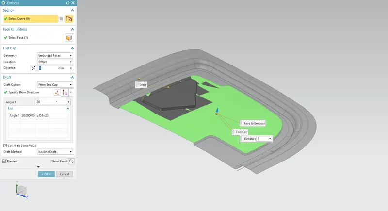
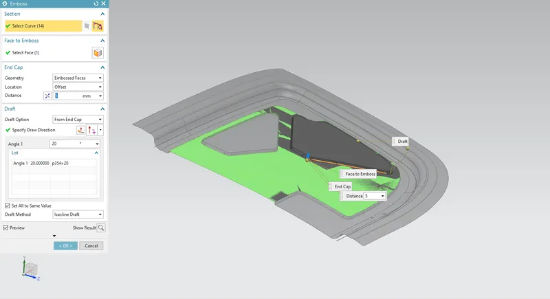
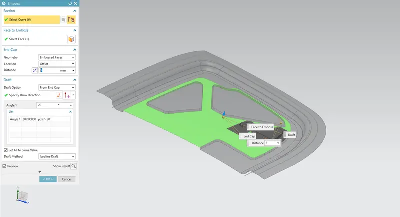
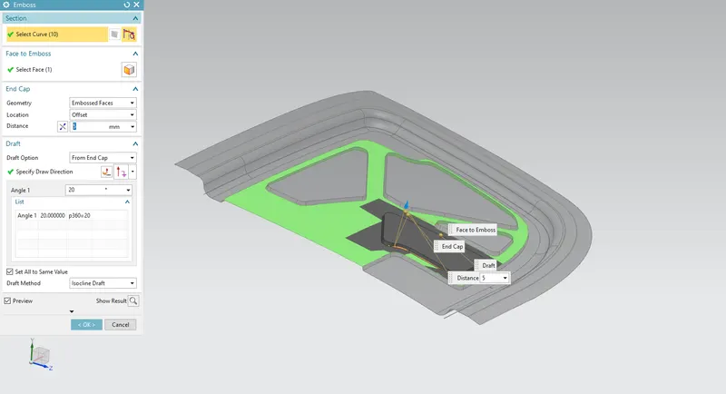
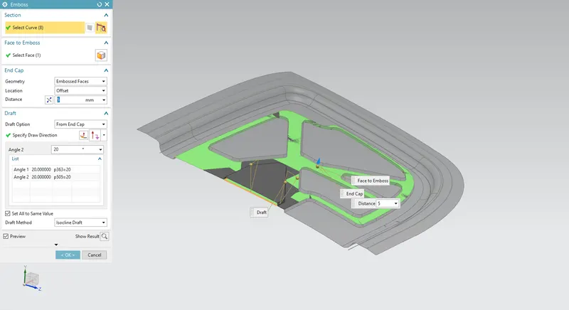
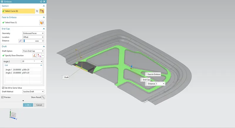
Create the sketch, project it on the surface, and trim it.
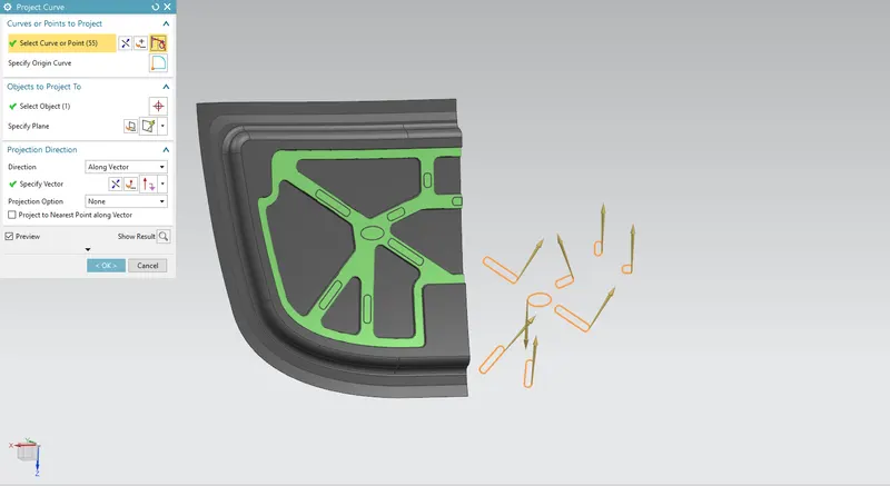
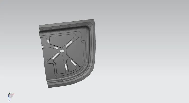
Now add face blend and edge blend between the created surfaces.
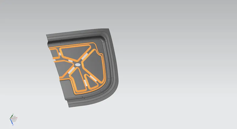
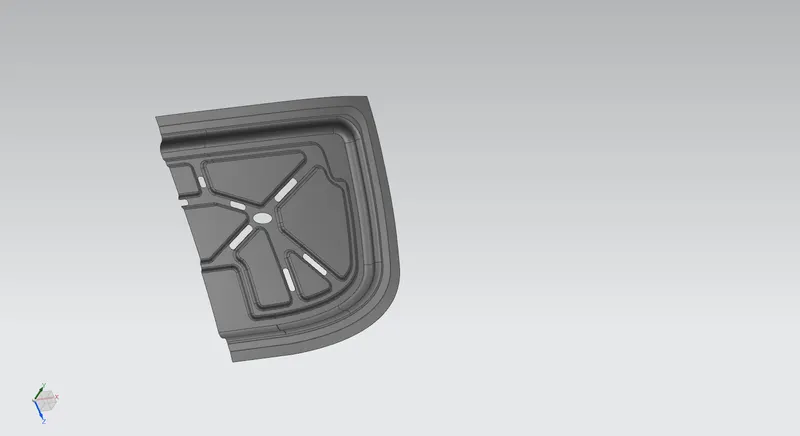
Create the sketch and project it on the surface, and trim it.
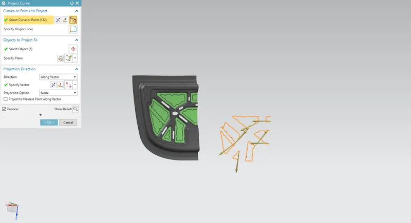
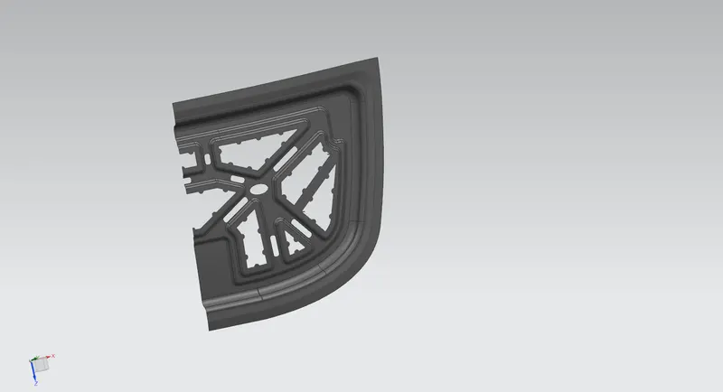
Take a raw estimation of the location of the striker and hinge and create a emboss with a flat surface, also apply edge blends.
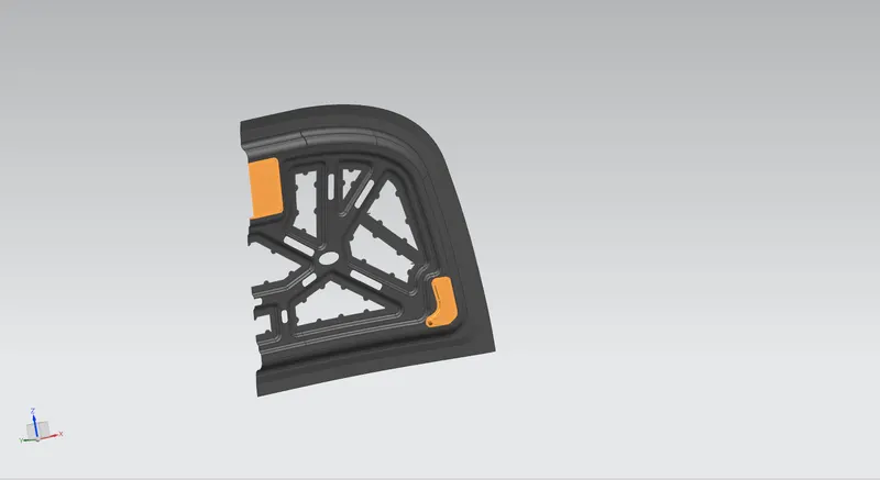
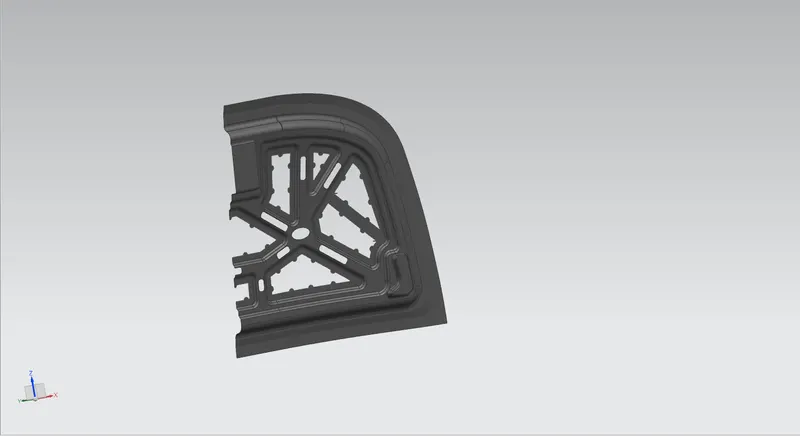
Take a proper estimation of the location of the striker and hinge by using moving and using WAVE Geometry Linker, and create the embosses.
(Note: This part is edited with respect to the hood opening trajectory and has already been considered and adjusted according to the requirements needed. This is re-edited after considering the hood opening trajectory which is done in assembly.)
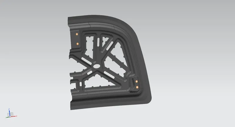
Use WAVE Geometry Linker to get the hole position of the holes in the striker and hinge, then trim it.
Mirror the geometry.
Sew both sheet geometry together.
By using thicken command, add the thickness of 0.75 mm in an upward direction to finally create the inner panel.
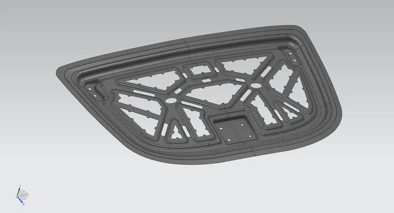
To create the Outer Panel:
Create a 0 mm offset of the outer panel to use it as a working surface.
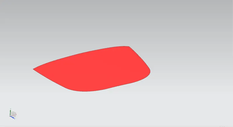
Trim the surface into half w.r.t YZ plane and create an offset of 0.75 mm from this surface. Hide the earlier surfaces.
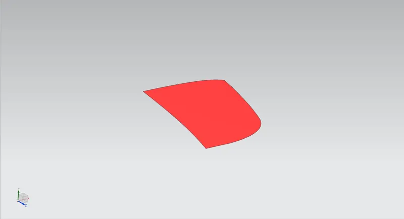
Extend the selected edges of the sheet by about 0.5 mm in the outward direction.
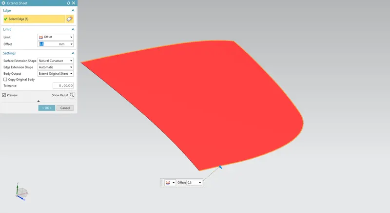
Select the extended edges again and create an offset on the face of 0.5 mm in the inward direction.
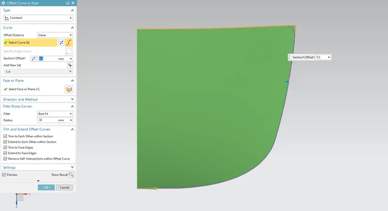
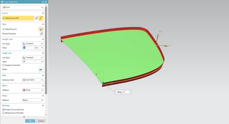
Create a law extension using this created offset curve.
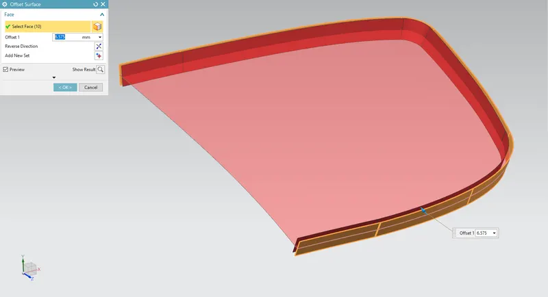
Create an offset surface from this law extension of 6.575 mm in the inward direction.
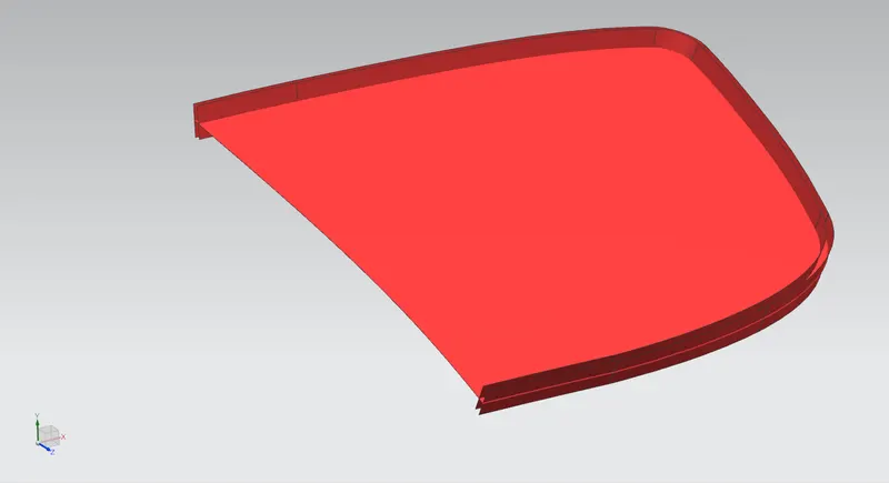
Create an offset surface from the selected surface of about 1.15 mm in the downward direction.
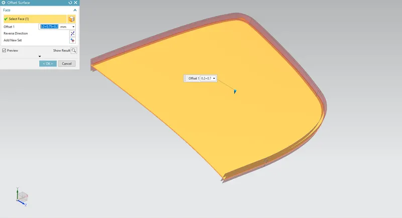
Hence, we achieve the required surfaces.
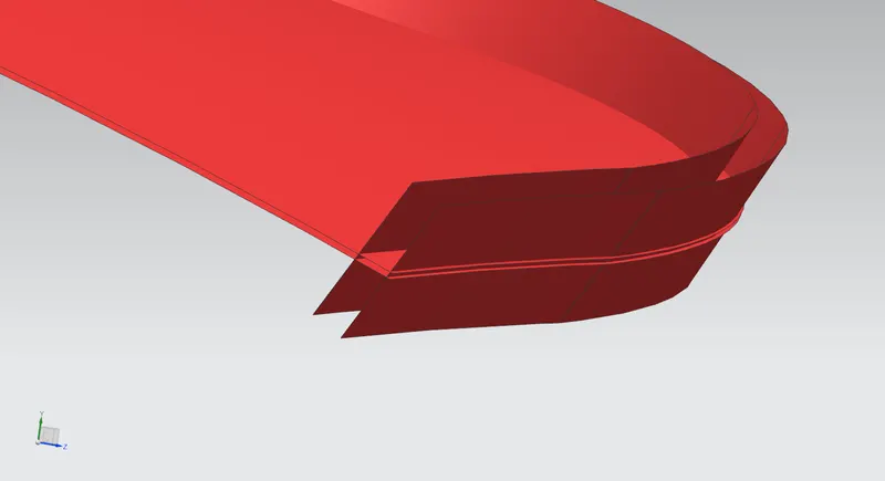
Use Trim Sheet to remove the unnecessary surface.
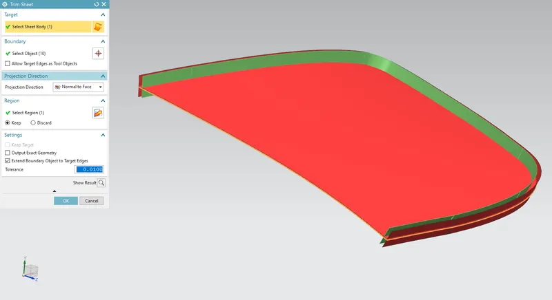
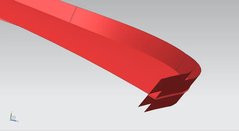
Click and hide the selected surface.
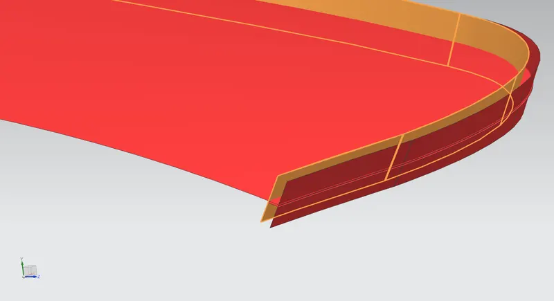
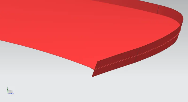
Add face blend between remaining three surfaces using three face option.
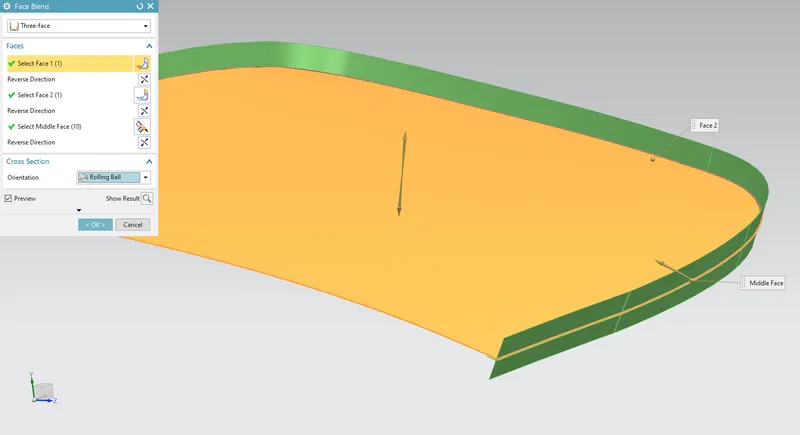
Click and hide the selected surface.
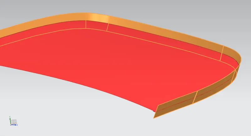
Hence, we get the required surface geometry.
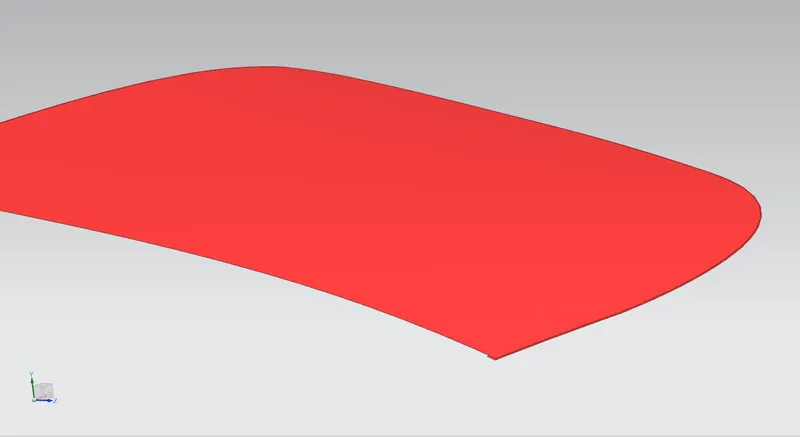
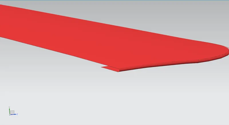
Create a sketch and project on the selected surface to provide rear relief, then trim the surface.
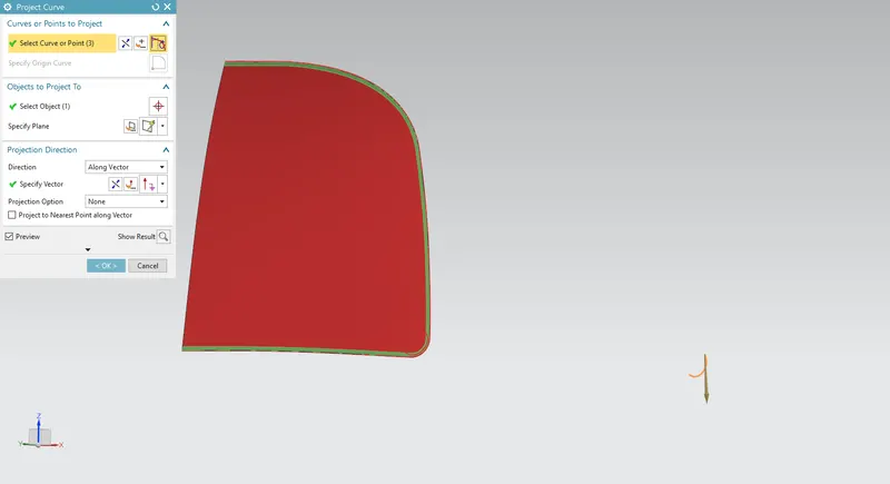
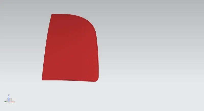
Create a sketch and project on the selected surface to provide front relief, then trim the surface.
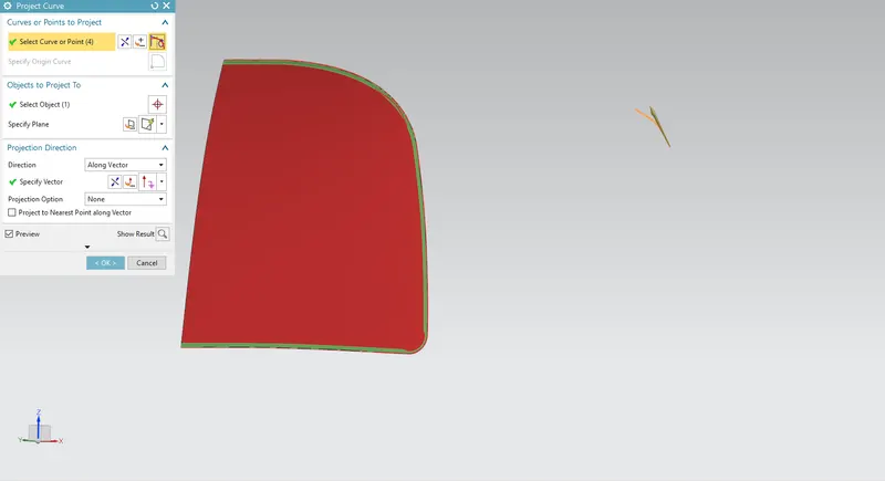
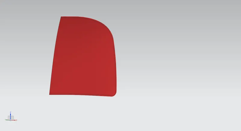
Mirror the geometry
Sew both sheet geometry together
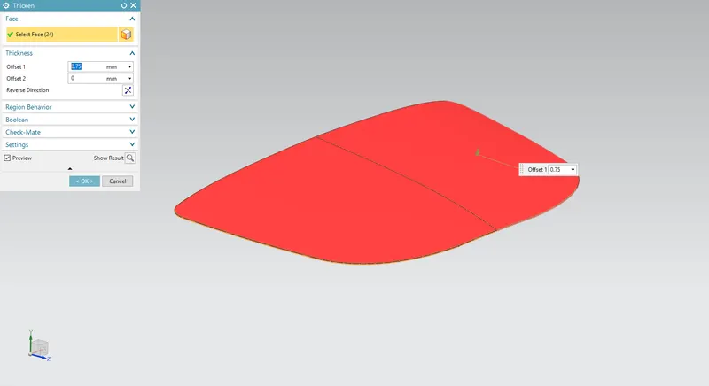
By using thicken command, add the thickness of 0.75 mm in the upward direction to finally create the outer panel.
To create the Reinforcements:
By using WAVE Geometry Linker, copy the selected curves from the inner panel to create reinforcements.
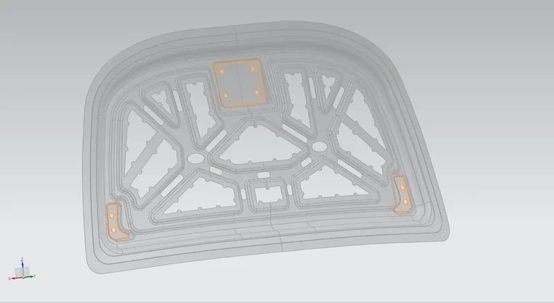
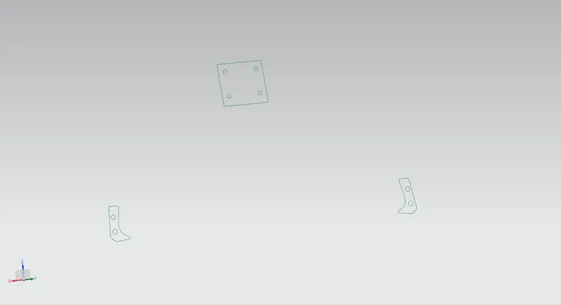
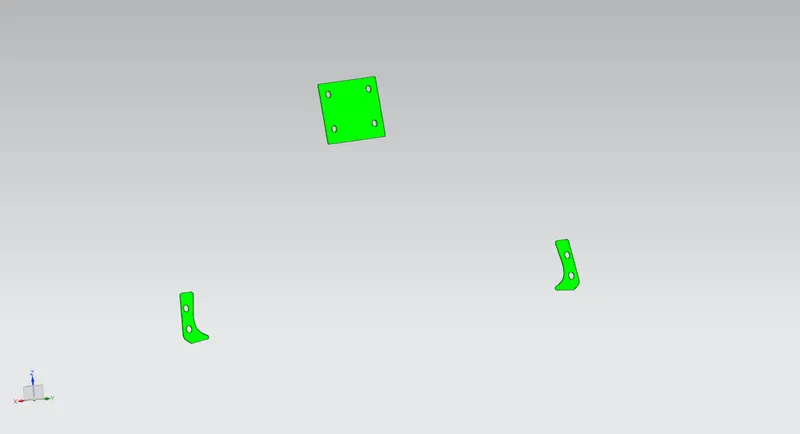
Create an extrude of 1.5 mm using these linked curves.
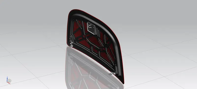
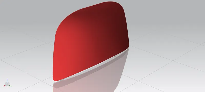
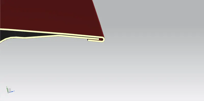
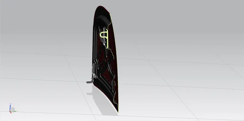
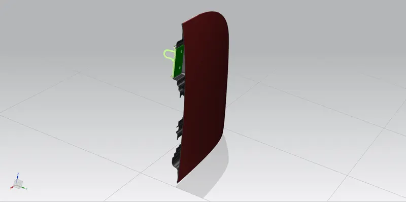
Final Assembly:
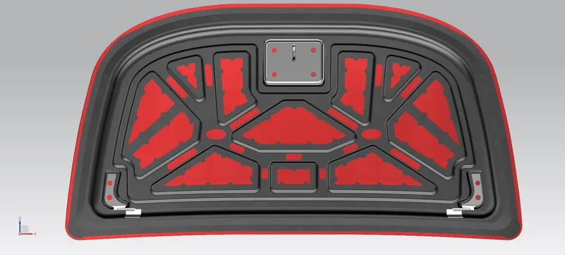
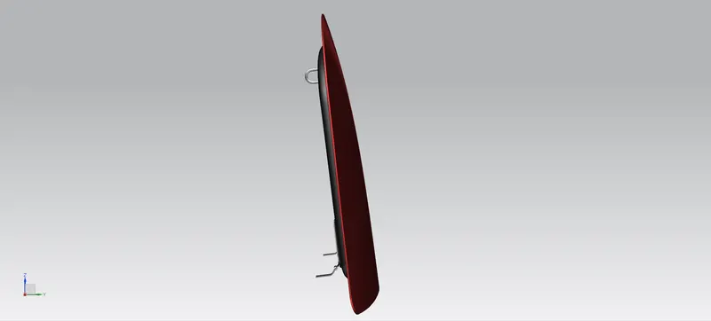
Draft Analysis:
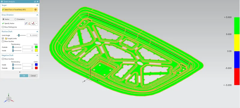
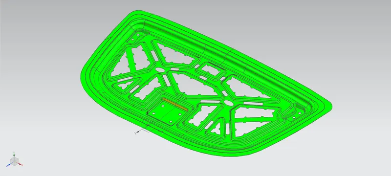
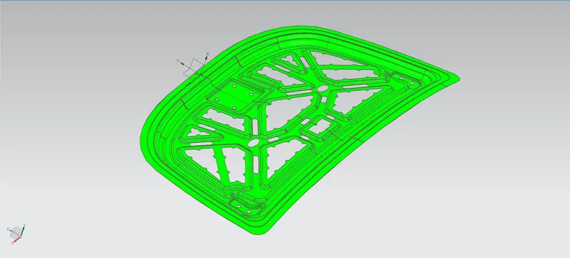
The Draft Analysis command enables us to detect if the part we drafted will be easily removed. This type of analysis is performed based on color ranges identifying zones on the analyzed element where the deviation from the draft direction at any point, corresponds to specified values. The Draft Analysis allows the designer to easily analyze a part for proper draft angle. A Draft Angle describes the amount of taper for molded or cast parts perpendicular to the parting line.
Conclusion:
All the parts of the hood are designed according to manufacturing requirements and to the dimensions given in the Master Section/Given data.