Week 9 - Project 1 - Door Trim Lower with Engineering Features
Door Trim Lower with Engineering Features
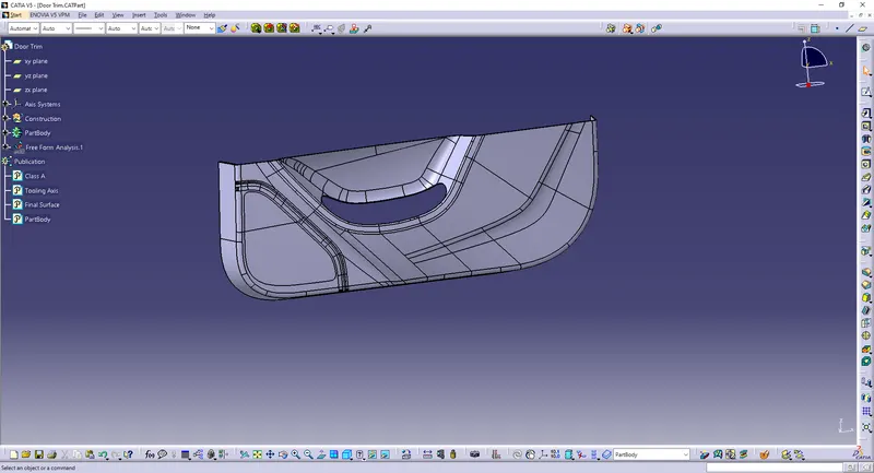
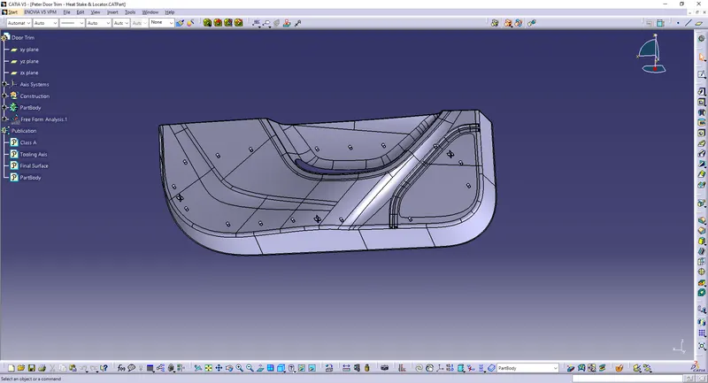
Objective:
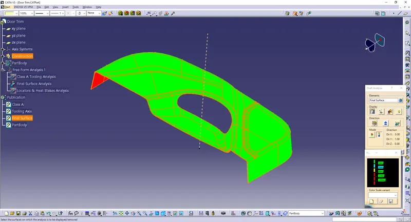
Create the Door Trim Plastic component through the given Class-A surface. To begin with, the tooling axis for the given Class-A Surface should be created meeting the requirements of the draft angle and at the end perform the Draft analysis on the model.
Take the Thickness of the component to be 2.5 mm.
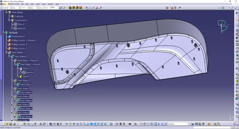
Create the Heat Stakes and the locators considering the design rules mentioned.
Creation of Tooling Axis:
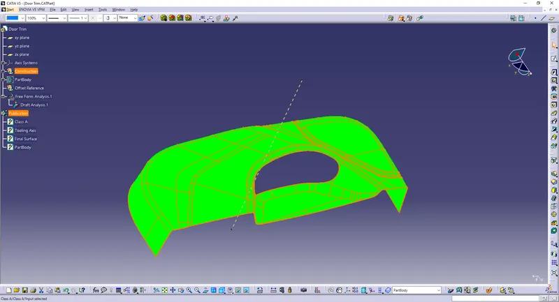
For Creating the tooling axis, we create a straight line from the selected point on the surface in the Y direction.
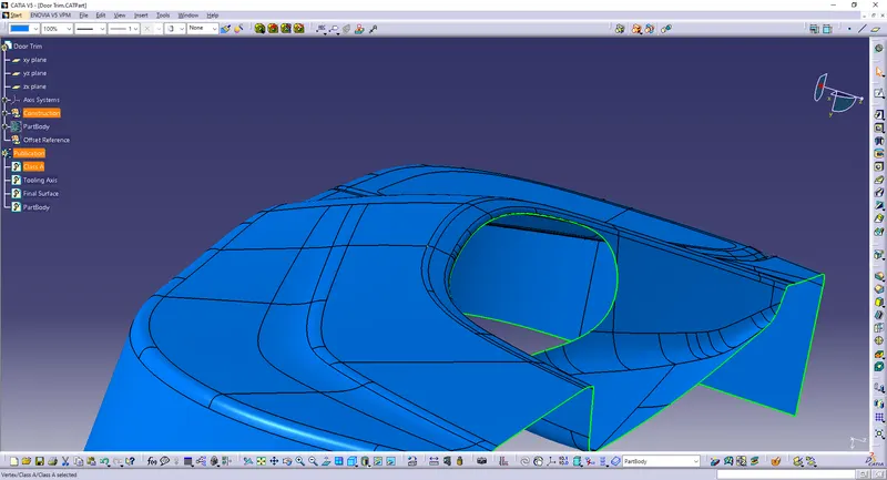
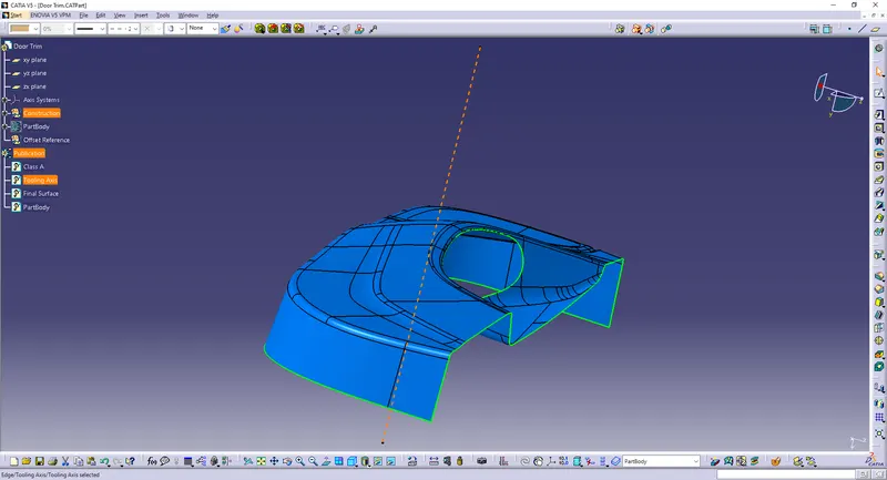
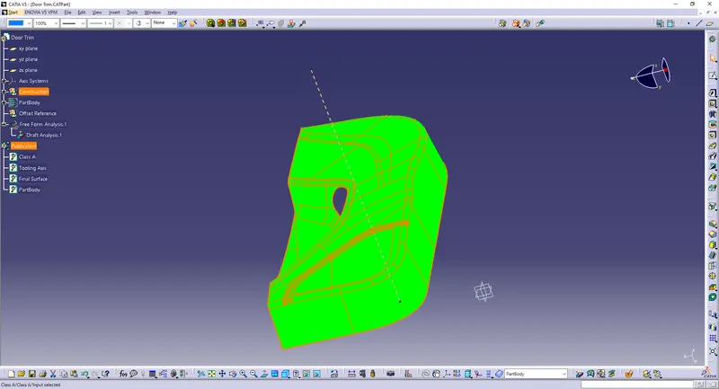
Checking the tooling axis by draft analysis.
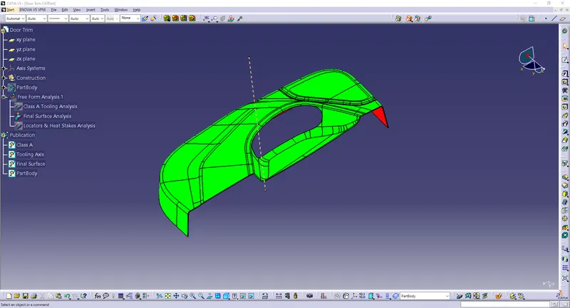
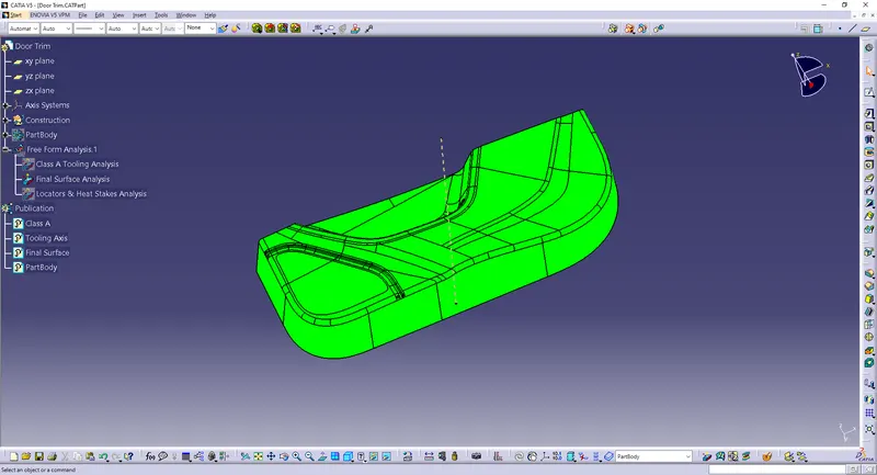
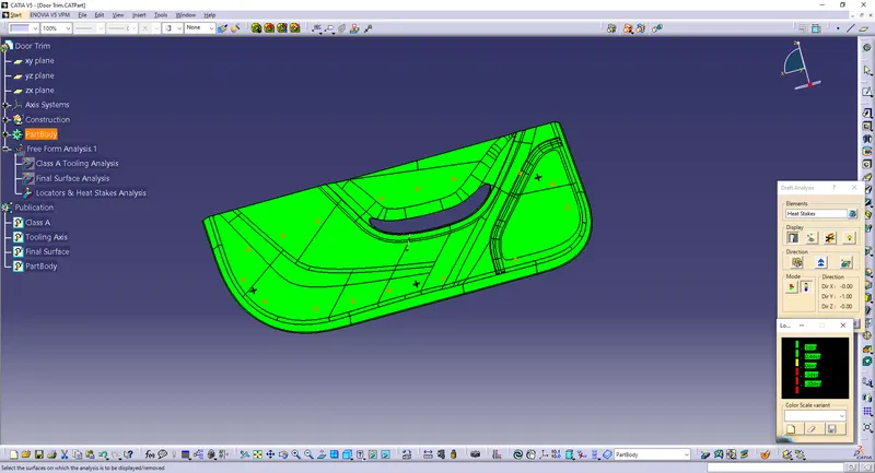
The draft analysis is done to determine if the designed part is tool able or not. Here the tooling axis is 3°.
By using the compass option, drag and place it on the tooling axis. Click ok then check the result.
Part Design:
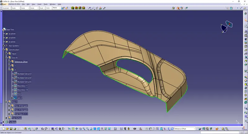
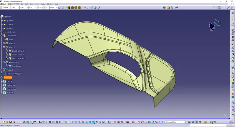
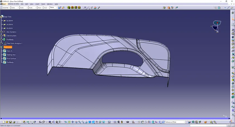
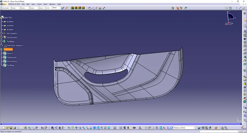
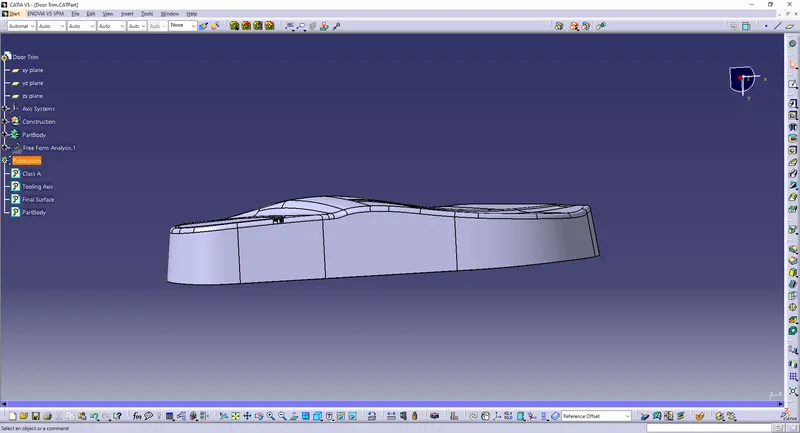
The B surface is created by an offset value of 2.5 mm:
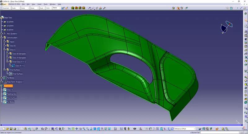
The C surface:
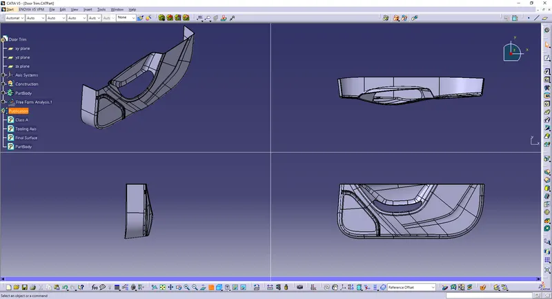
Locators:
Sketch Plane is made in the tooling axis direction.
Height = 20 mm
Wall Thickness = 1.3 mm
Draft Angle = 0.5°
Chamfer = 3 mm, 45°
Fillet 0.3 mm & 3 mm
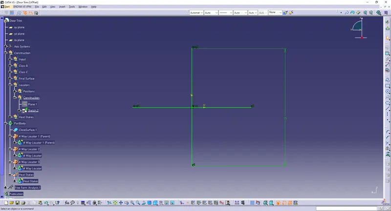
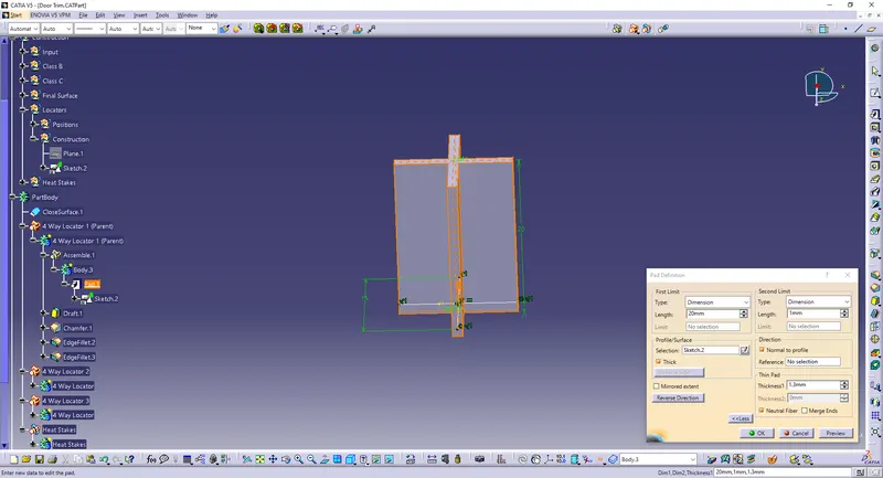
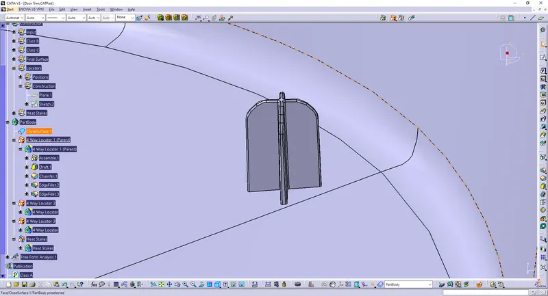
Use copy and paste special to translate them to other locations.
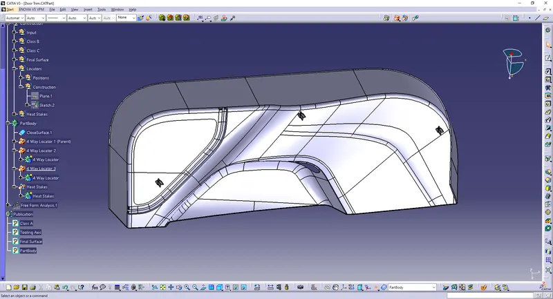
Heat Stakes:
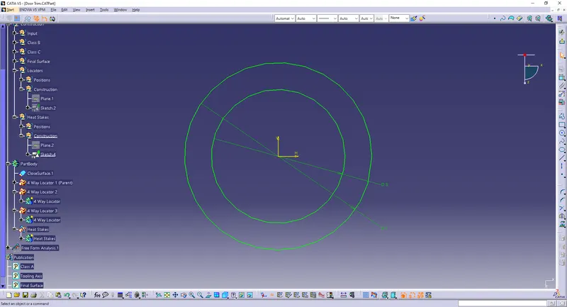
Sketch Plane is made in the tooling axis direction.
The length of heat stakes should be at least 5 mm lesser than locators, L = 15mm
Radius, ID = 5mm, OD = 7 mm
Draft Angle = 0.5°
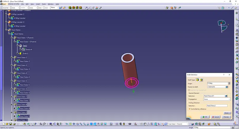
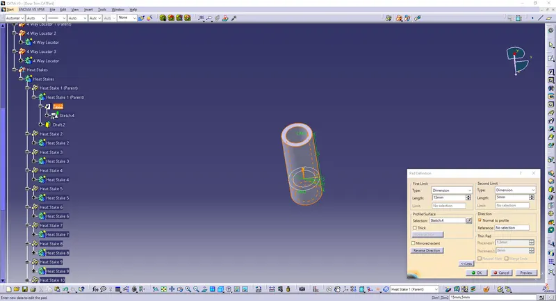
Use copy and paste special to translate them to other locations.
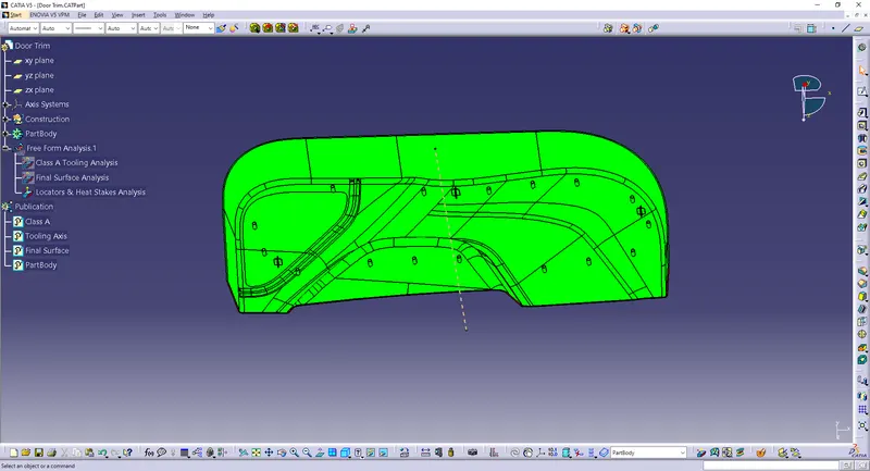
Final Draft Analysis:
Part:
Locators and Heat Stakes:
Conclusion:
The part has been designed as per the design requirements.