Wiring harness design in CATIA V5 - 3D modeling Week 5 & 6 Challenge
Wiring harness design in CATIA V5 - 3D modeling
Objective:
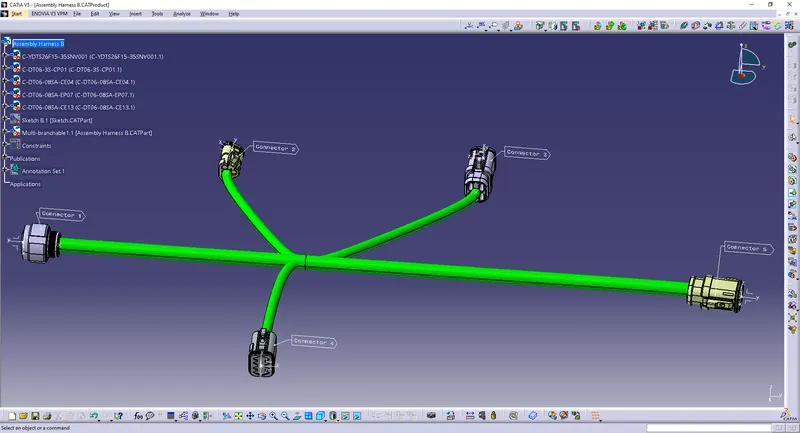
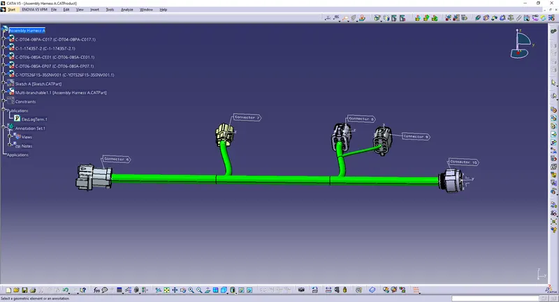
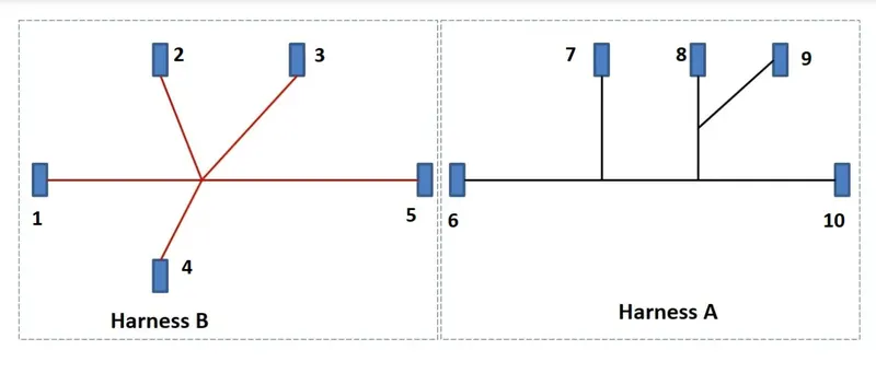
Route the following harness layout in the Electrical workbench. Make assumptions for harness bundle diameters. Use the connectors provided. After completion of routing,
- Check the bundle Continuity. Add a snap of the result in the submission
- Add annotation to all connectors. Make assumptions for annotations like connect 1, 2, etc
- Check for the bundle warning. Add snap.
- Generate CAT.part of harness assembly and convert it in .igs format.
Given Routing Layout:
Procedure:
Give the Electrical properties to the downloaded connectors:
1) c-ydts26f15-35snv001-99-3d
Create a point on the mating surface.
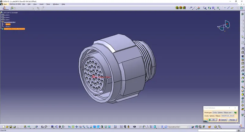
Create a point at the back as the bundle entry point.
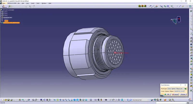
Create an axis on the point.
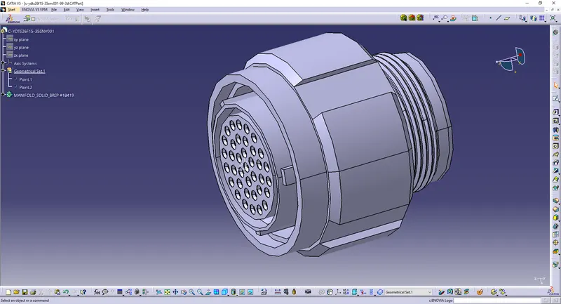
Define the part as a connector with 37 terminations.
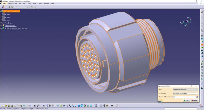
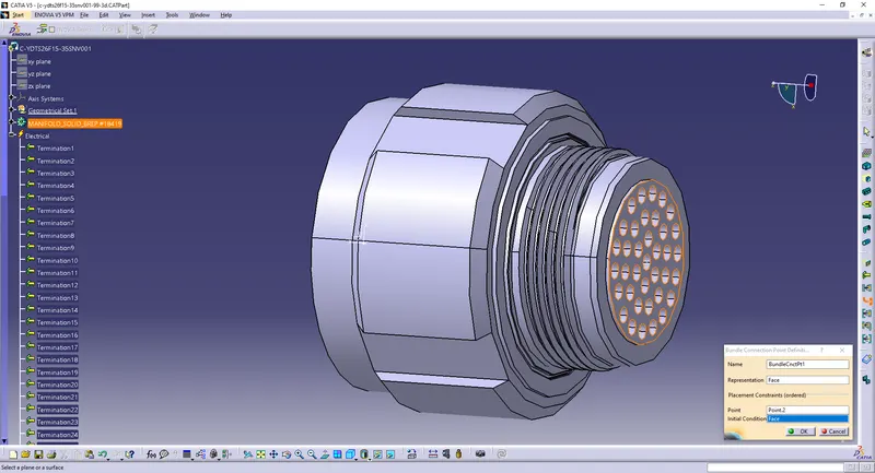
Define Bundle Connection Point.
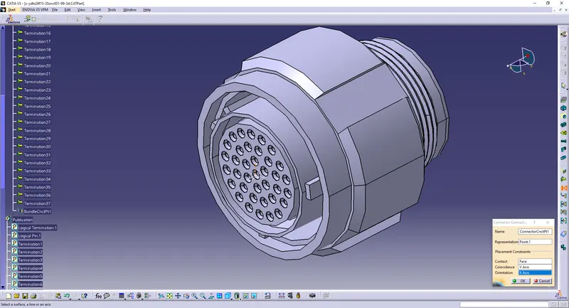
Define Connector Connection Point.
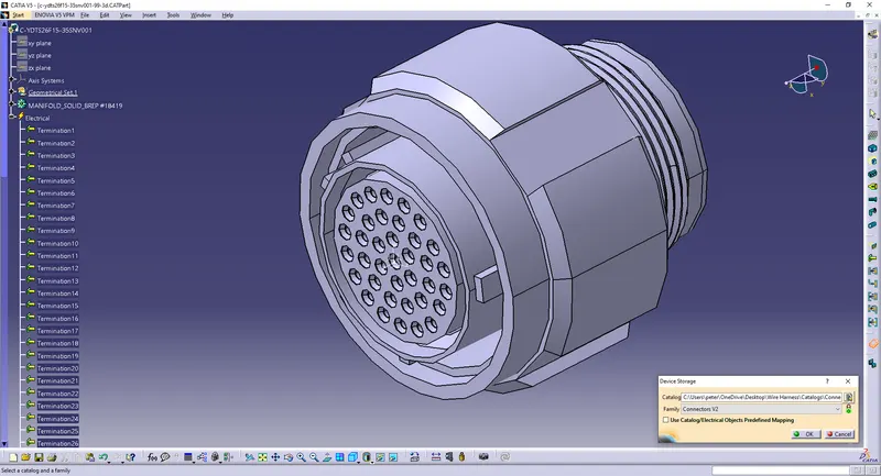
Save/Add it to the catalog.
2) c-dt06-08sa-ep07-99-3d
Create a point on the mating surface.
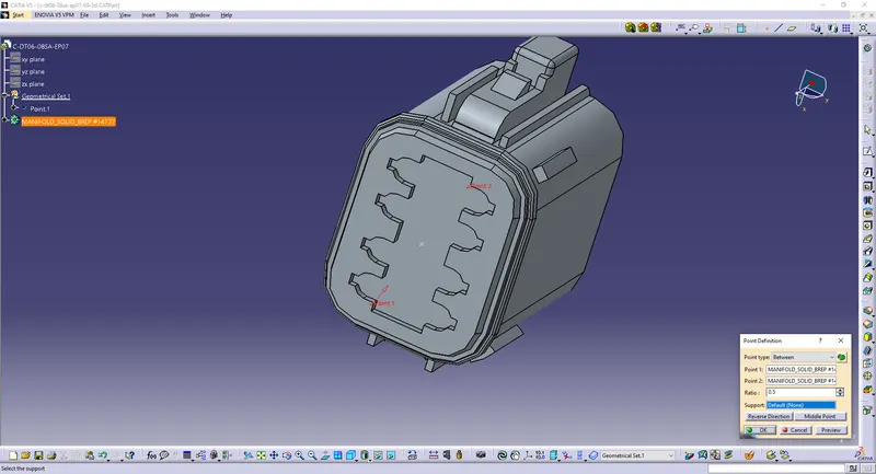
Create a point at the back as the bundle entry point.
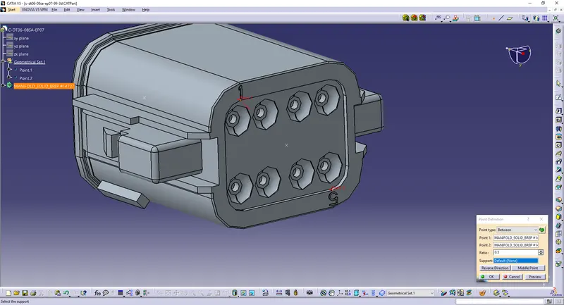
Create an axis on the point.
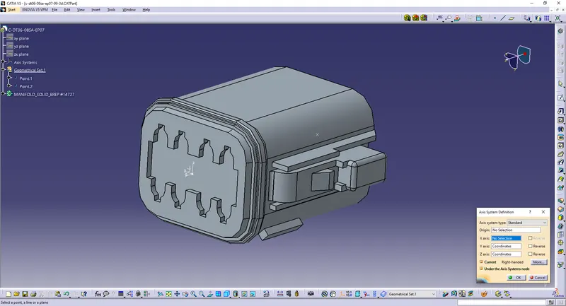
Define the part as a connector with 8 terminations.
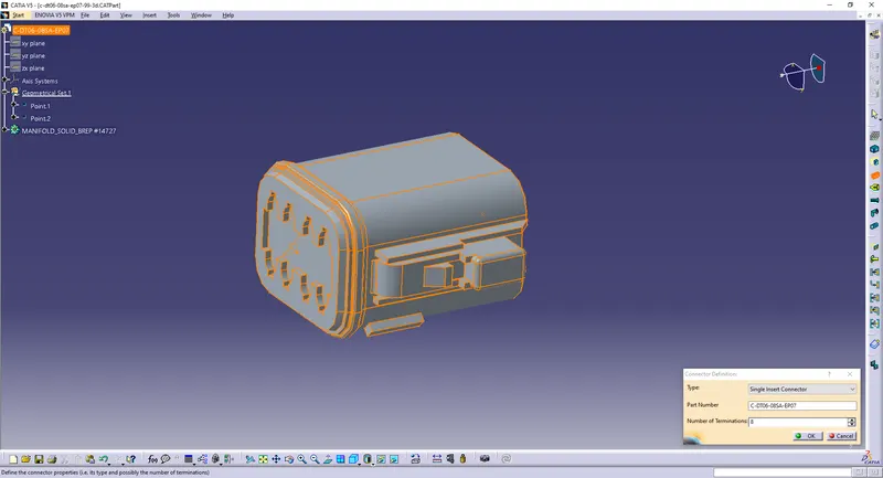
Define Bundle Connection Point.
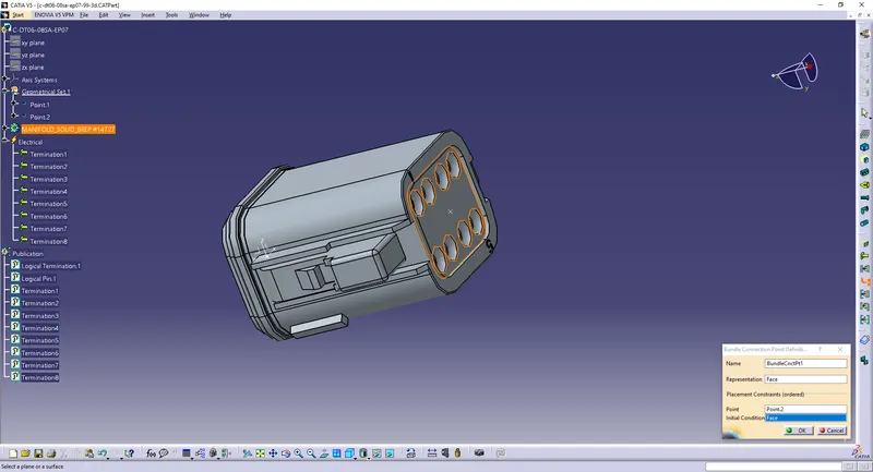
Define Connector Connection Point.
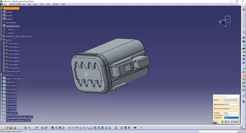
Save/Add it to the catalog.
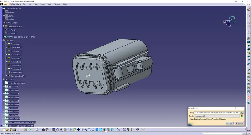
3) c-dt06-08sa-ce01-99-3d
Create a point on the mating surface.
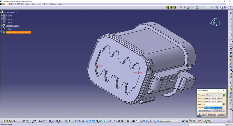
Create a point at the back as the bundle entry point.
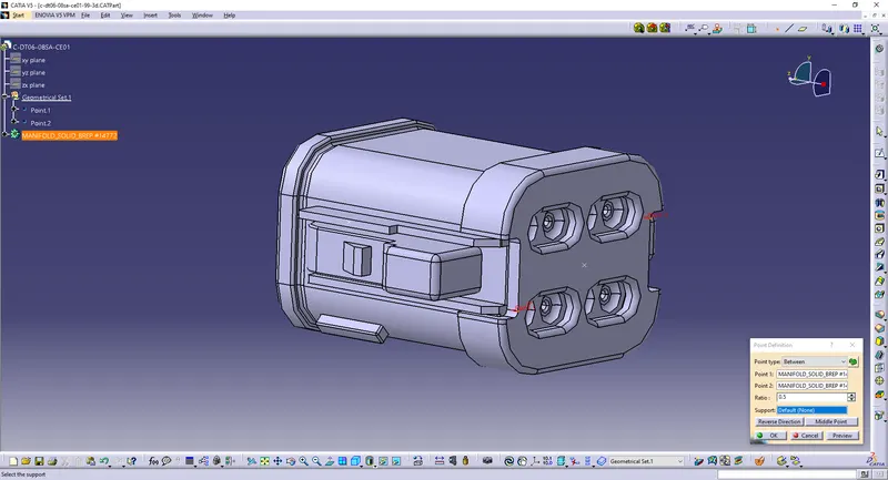
Create an axis on the point.
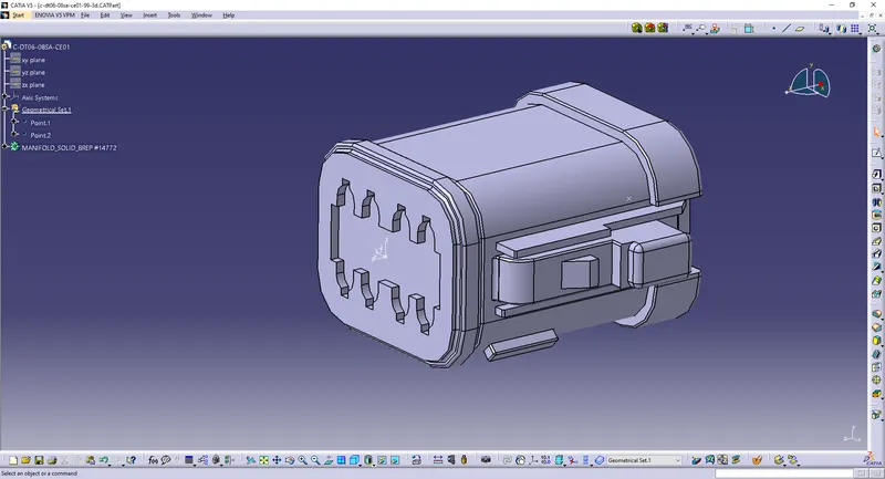
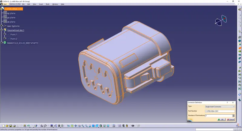
Define the part as a connector with 8 terminations.
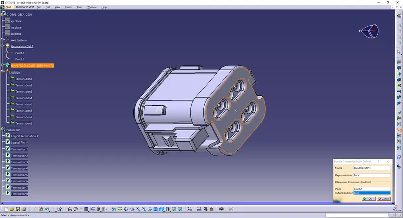
Define Bundle Connection Point.
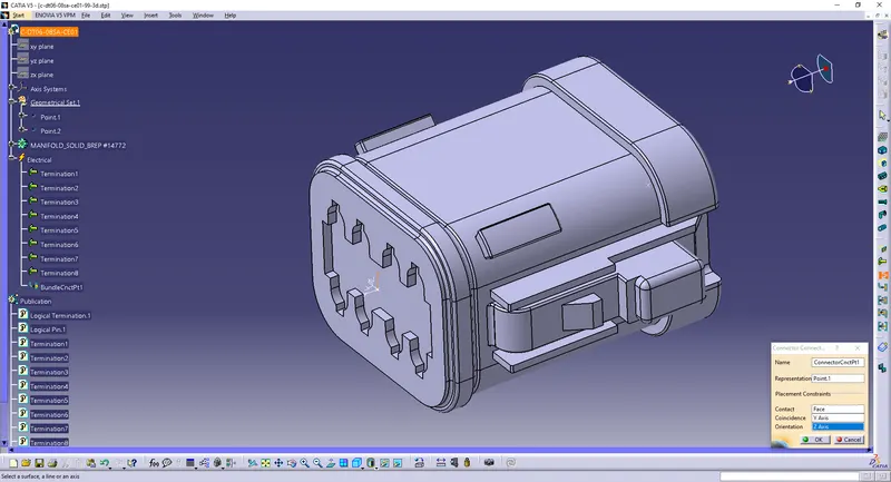
Define Connector Connection Point.
Save/Add it to the catalog.
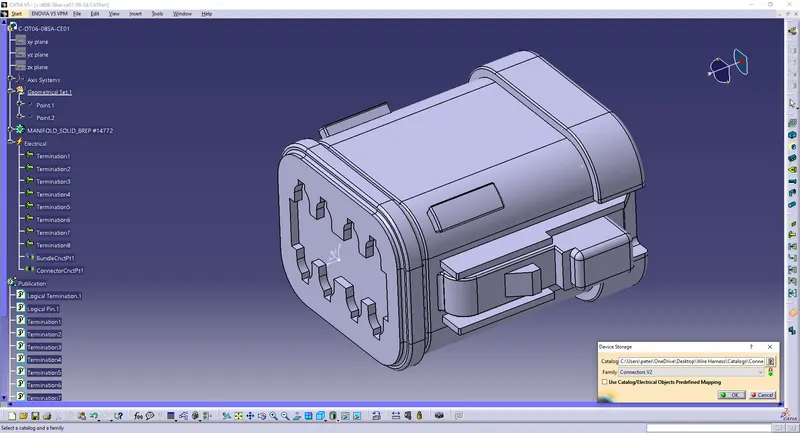
4) c-dt04-08pa-c017-99-3d
Create a point on the mating surface.
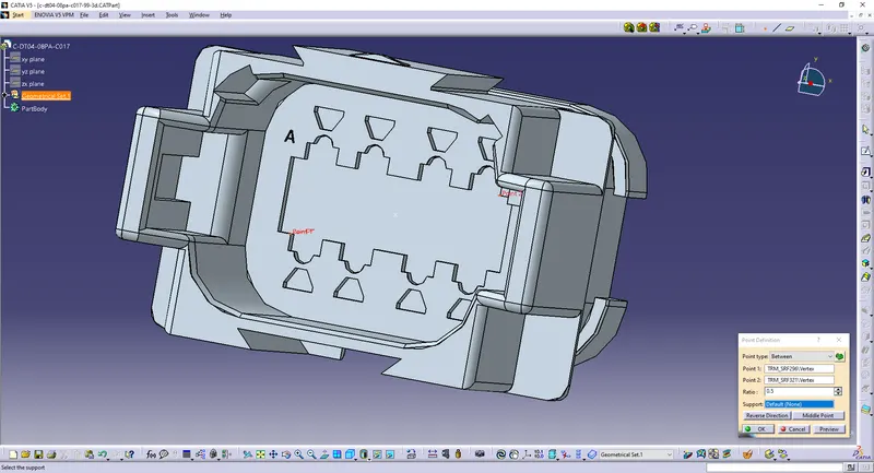
Create a point at the back as the bundle entry point.
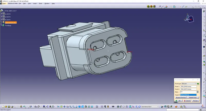
Create an axis on the point.
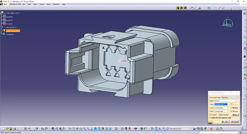
Define the part as a connector with 4 terminations.
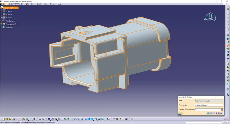
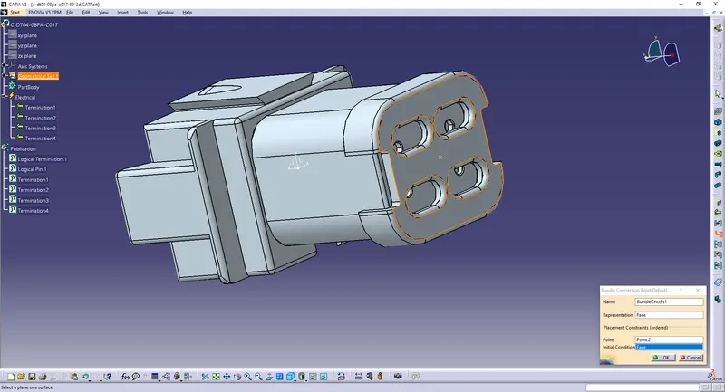
Define Bundle Connection Point.
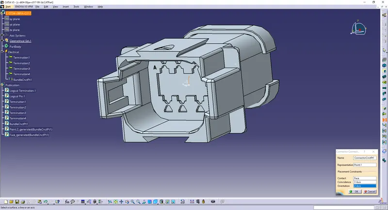
Define Connector Connection Point.
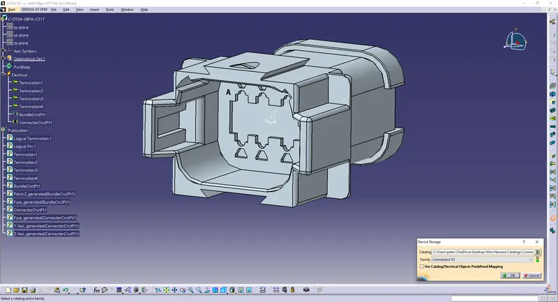
Save/Add it to the catalog.
5) c-1-174357-2-e-3d
Create a point on the mating surface.
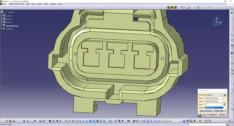
Create a point at the back as the bundle entry point.
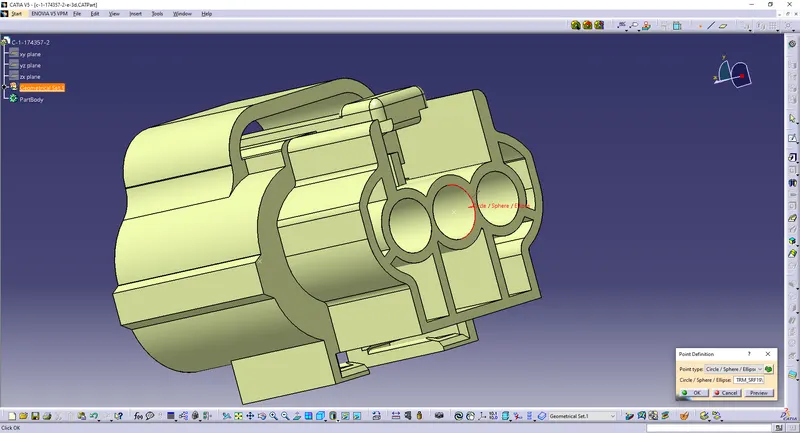
Create an axis on the point.
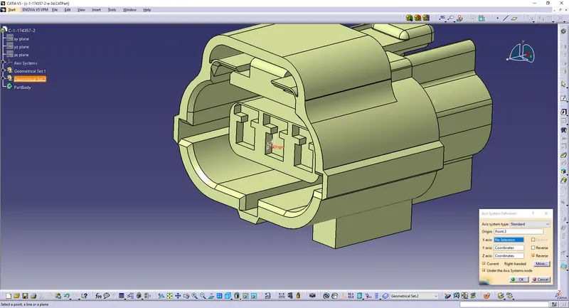
Define the part as a connector with 3 terminations.
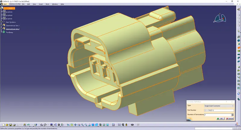
Define Bundle Connection Point.
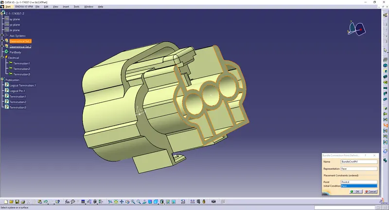
Define Connector Connection Point.
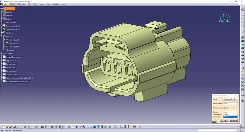
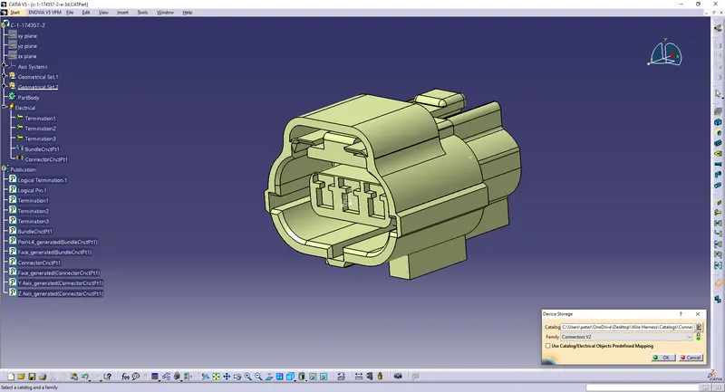
Save/Add it to the catalog.
6) c-dt06-3s-cp01-99-3d
Create a point on the mating surface.
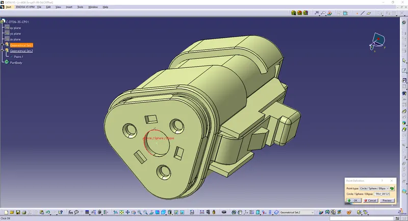
Create a point at the back as the bundle entry point.
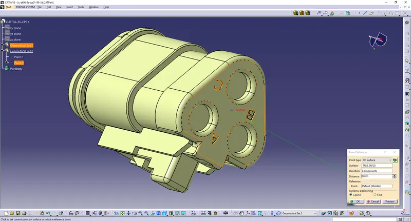
Create an axis on the point.
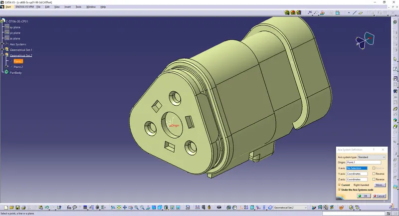
Define the part as a connector with 3 terminations.
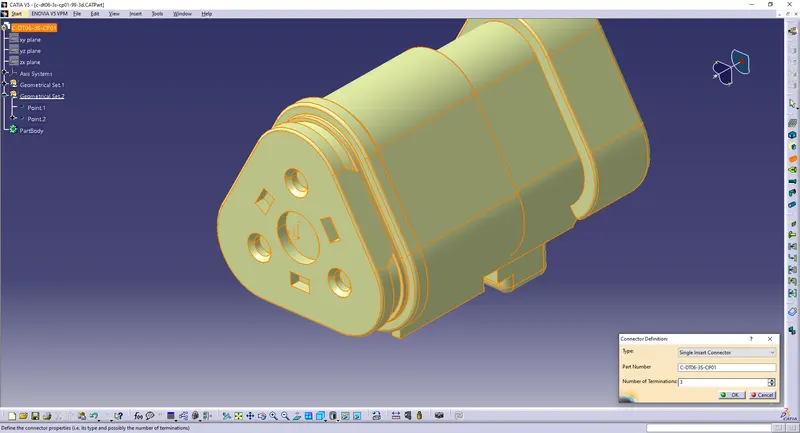
Define Bundle Connection Point.
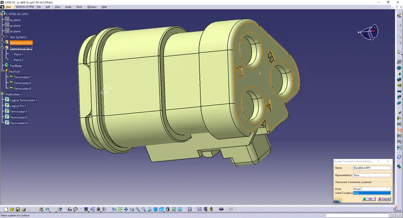
Define Connector Connection Point.
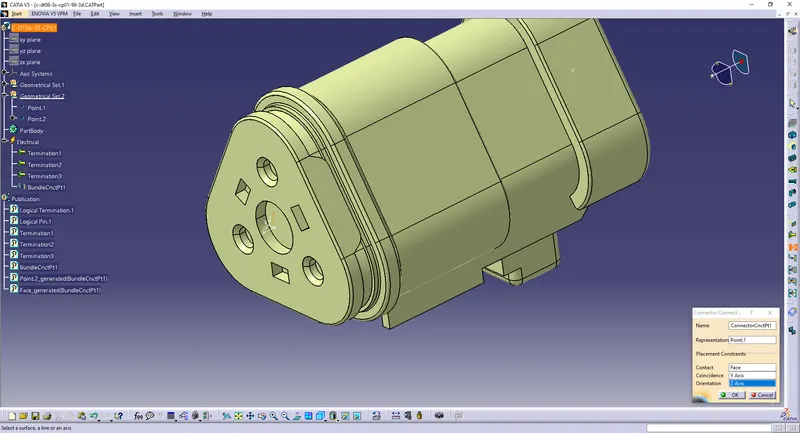
Save/Add it to the catalog.
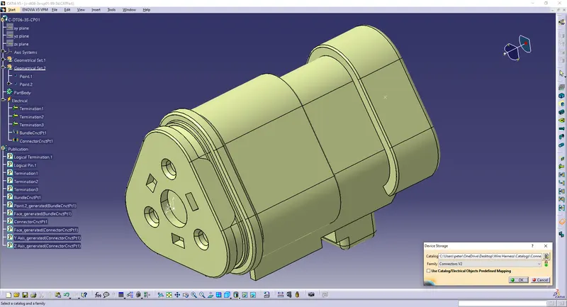
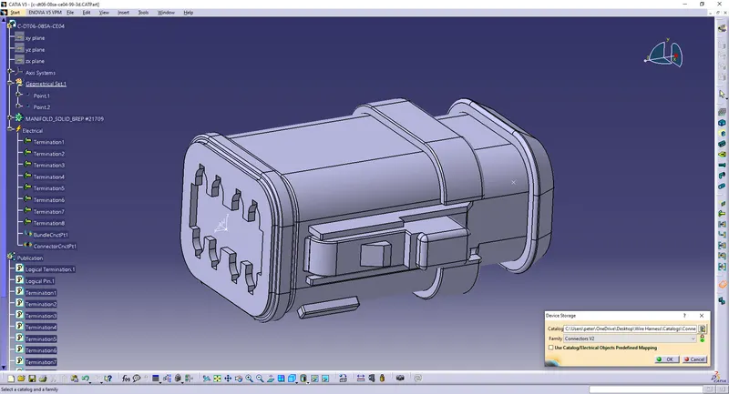
7) c-dt06-08sa-ce04-99-3d
Create a point on the mating surface.
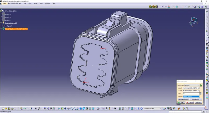
Create a point at the back as the bundle entry point.
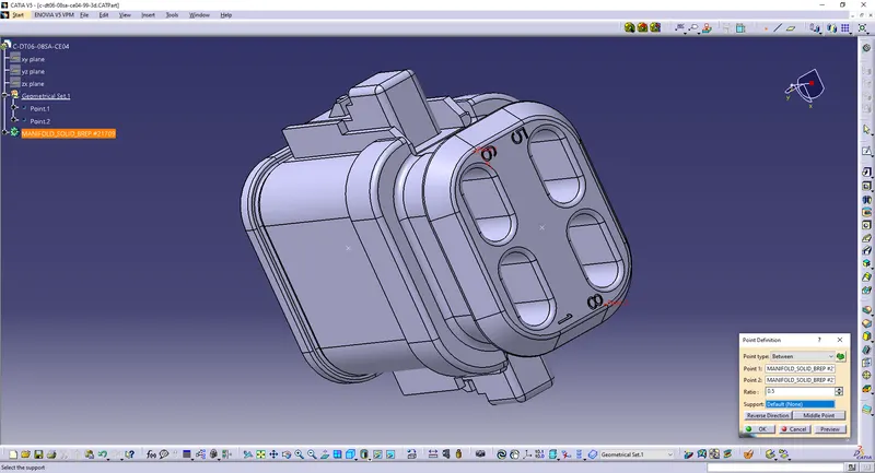
Create an axis on the point.
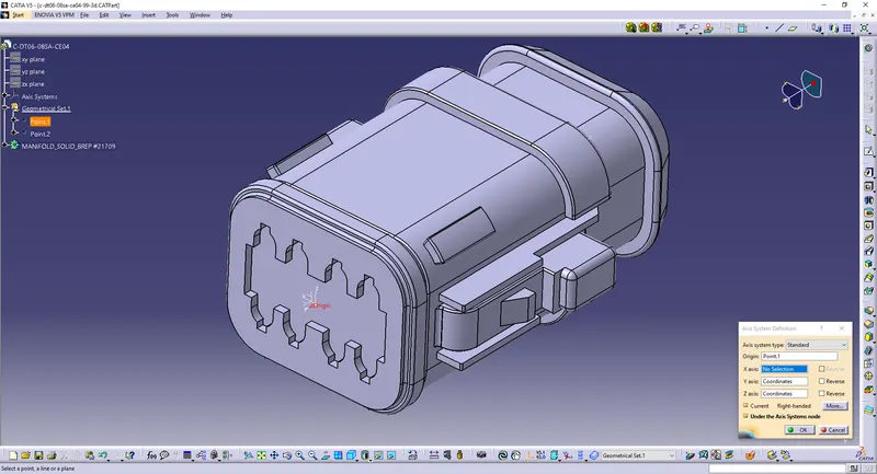
Define the part as a connector with 8 terminations.
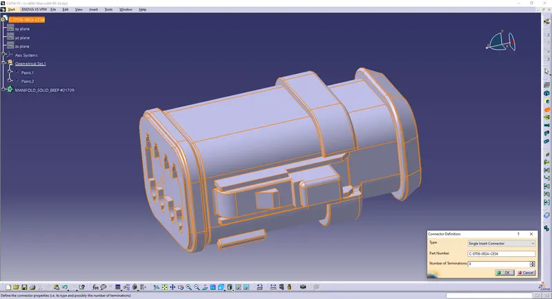
Define Bundle Connection Point.
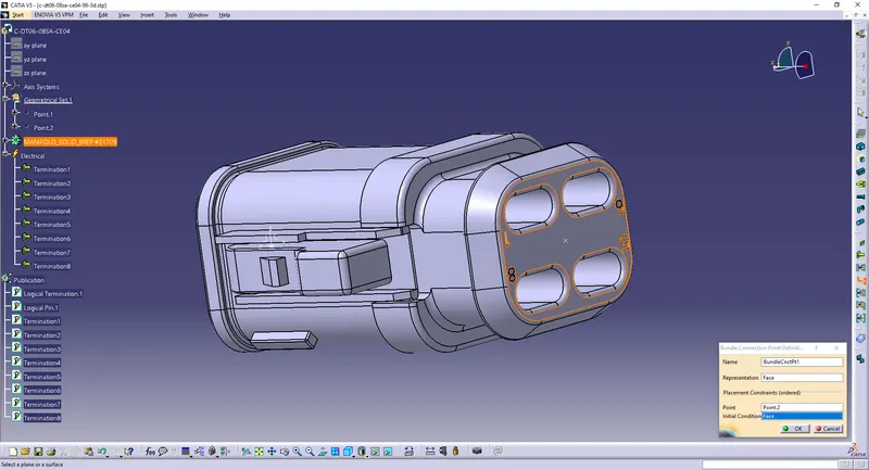
Define Connector Connection Point.
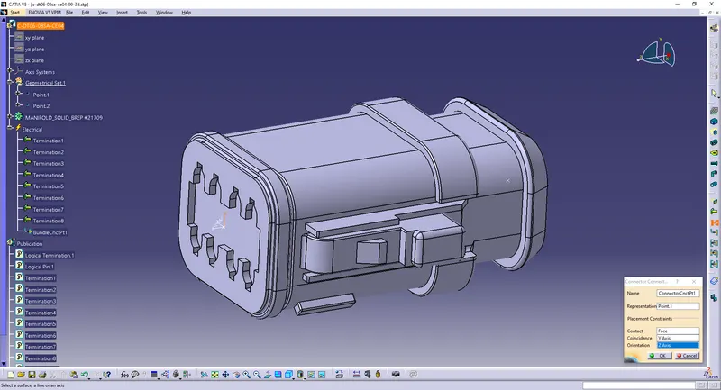
Save/Add it to the catalog.
8) c-dt06-08sa-ce13-99-3d
Create a point on the mating surface.
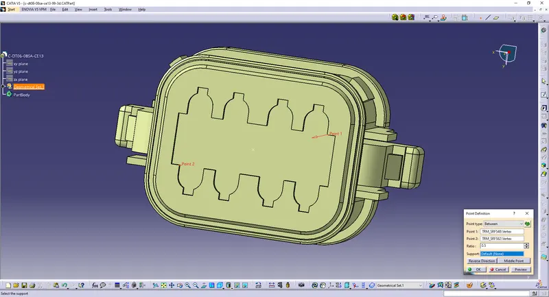
Create a point at the back as the bundle entry point.
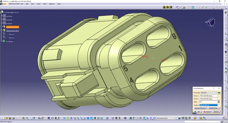
Create an axis on the point.
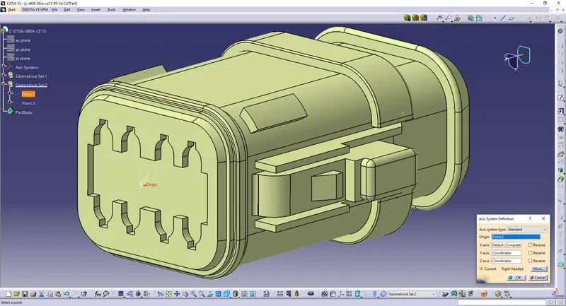
Define the part as a connector with 8 terminations.
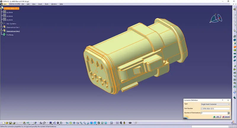
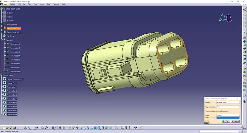
Define Bundle Connection Point.
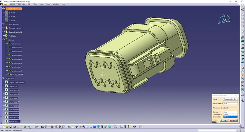
Define Connector Connection Point.
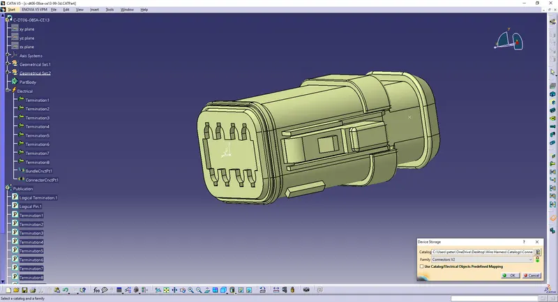
Save/Add it to the catalog.
Given Layout:
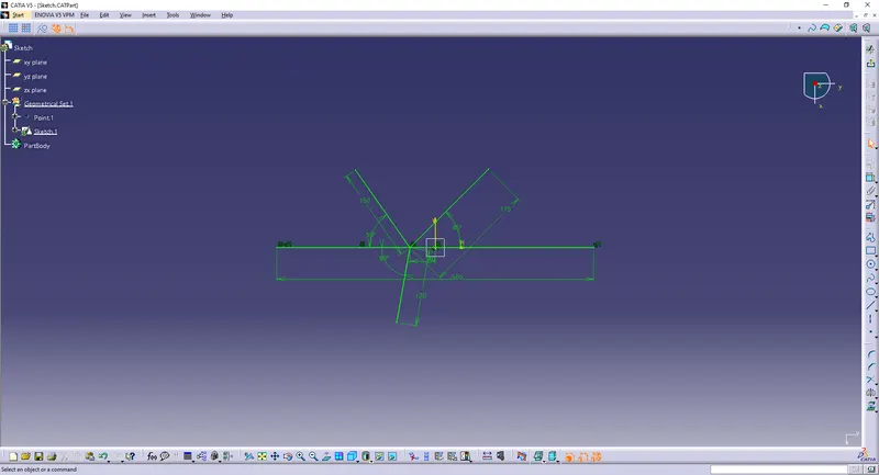
Assuming the dimensions.
Harness B:
Harness A:
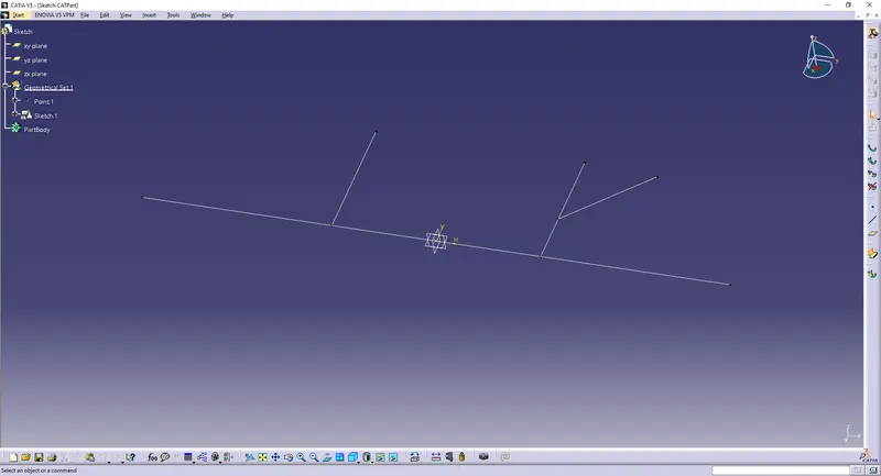
Open all the connectors and sketch in a new product file:
File>>New>>Product
Use 'Catalog Brower' to open the connectors
or
Copy and paste / Drag in the saved connector part files
Harness B:
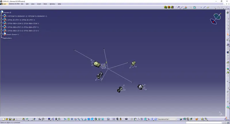
Use the 'Manipulation' and 'Smart Move' options to align the connectors.
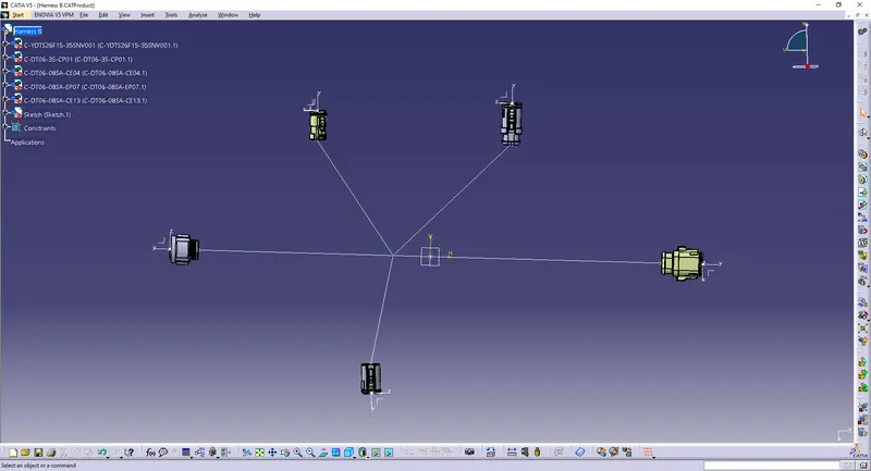
Use 'Multi-branchable Document' option and 'Branch Definition' to start connecting the connectors.
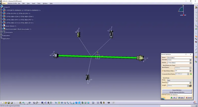
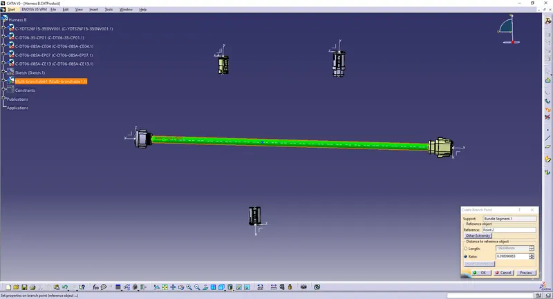
Use 'Add Branch Point' to create a branch point.
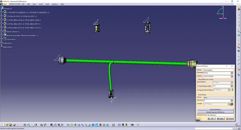
Use 'Branch Definition' to connect the connectors.
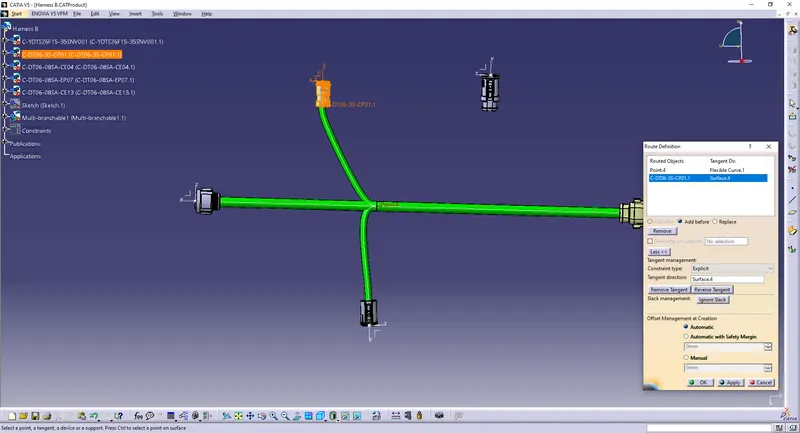
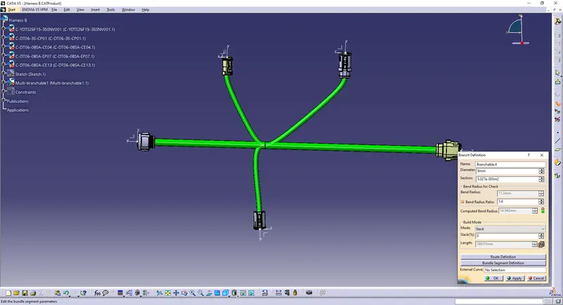
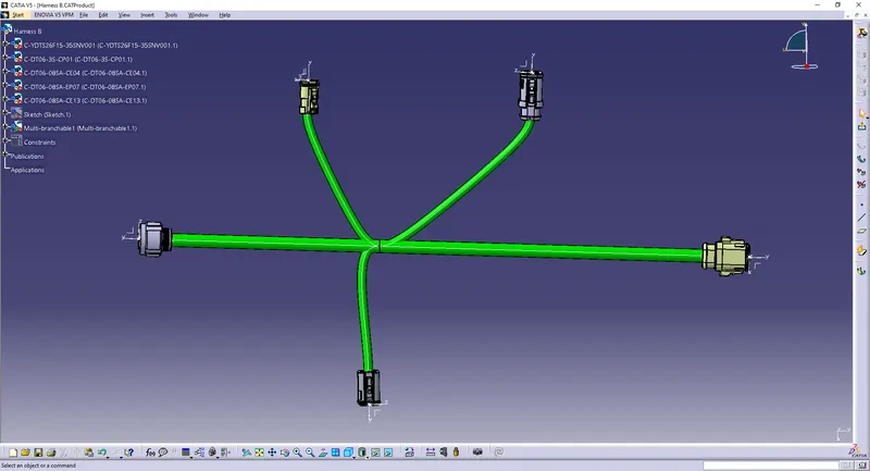
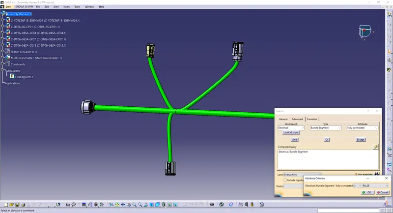
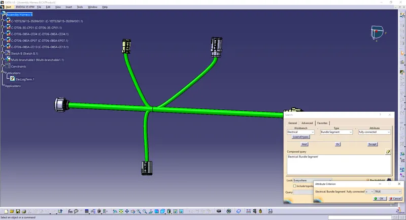
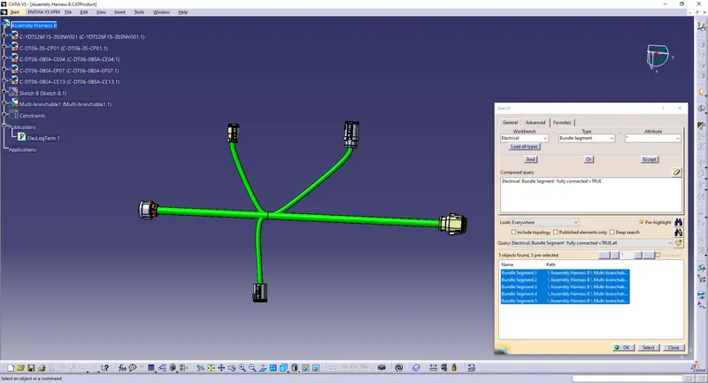
Check the bundle is continuous:
False to show unconnected
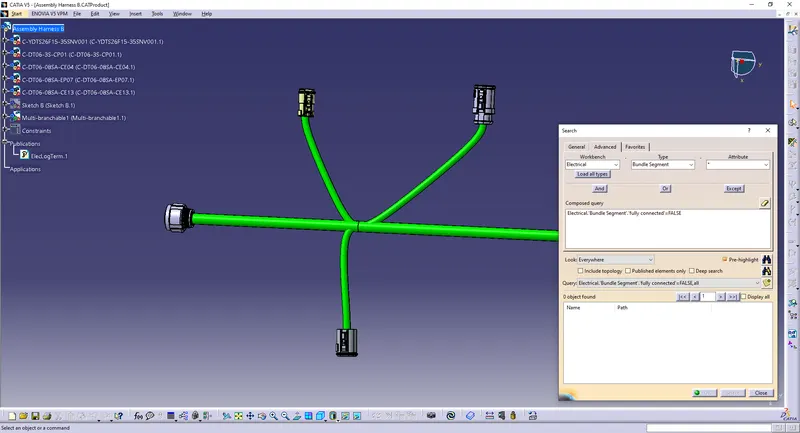
True to show connected
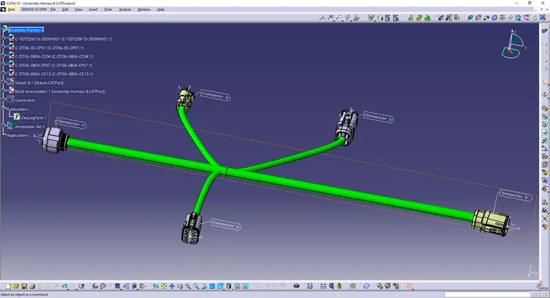
Adding Annotations:
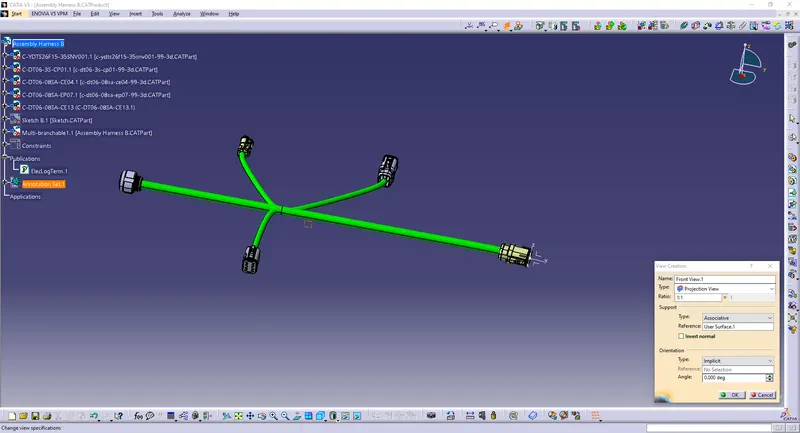
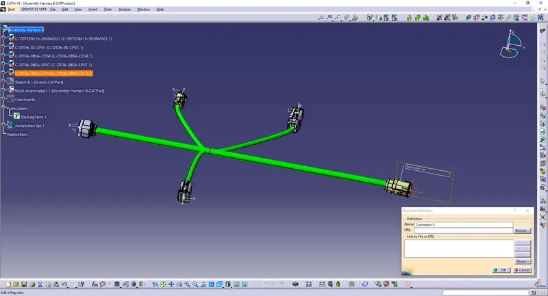
Create a plane using 'View Creation' option.
Use any note option to annotate the assembly.
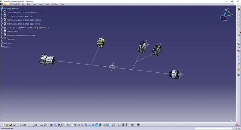
Harness A:
Use the 'Manipulation' and 'Smart Move' options to align the connectors.
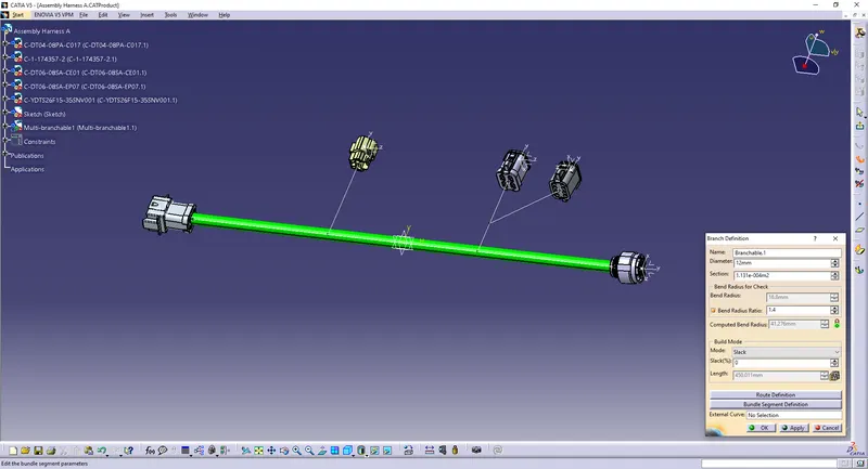
Use 'Multi-branchable Document' option and 'Branch Definition' to start connecting the connectors.
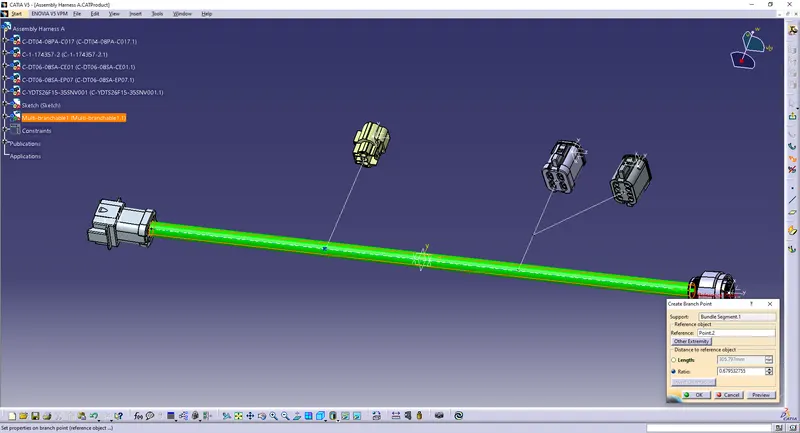
Use 'Add Branch Point' to create branch points.
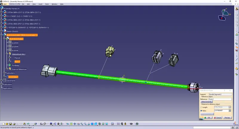
Use 'Branch Definition' to connect the connectors.
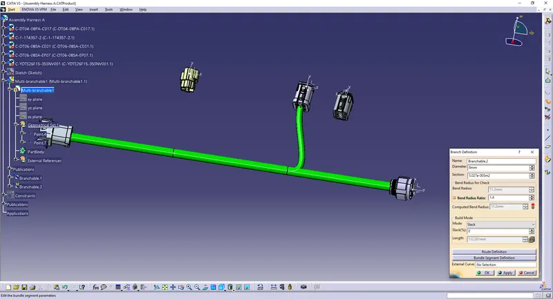
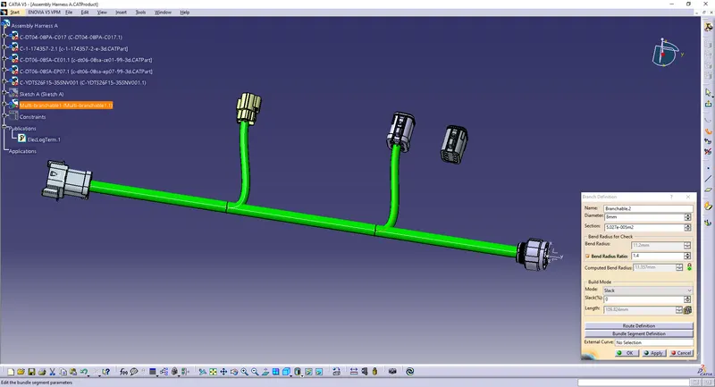
Use 'Add Branch Point' to create a branch point.
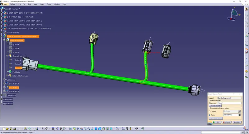
Use 'Branch Definition' to connect the connector.
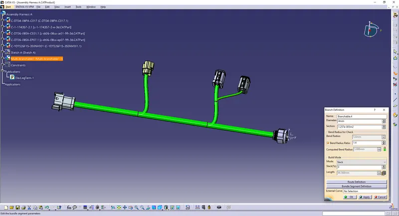
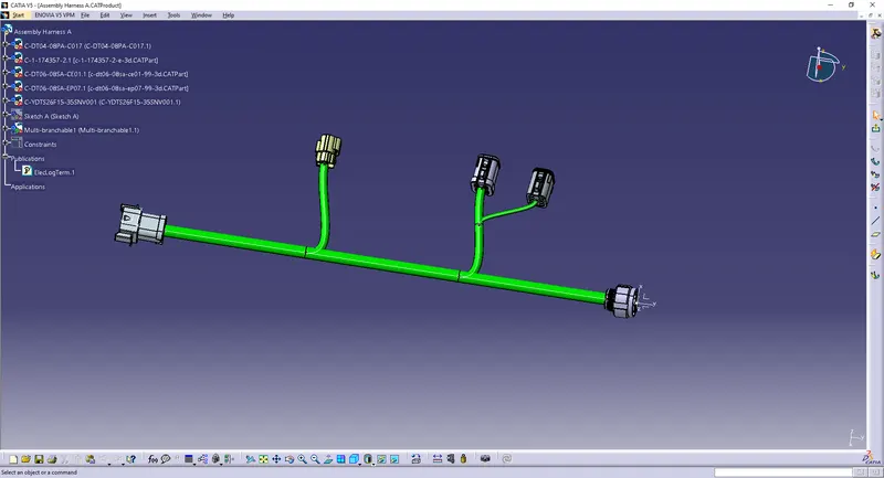
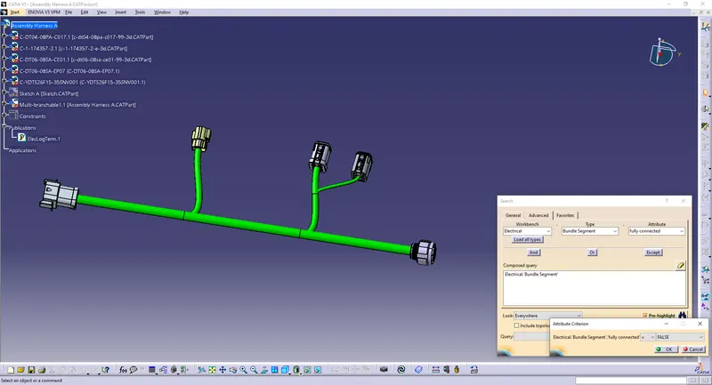
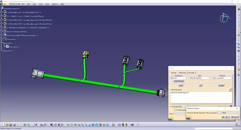
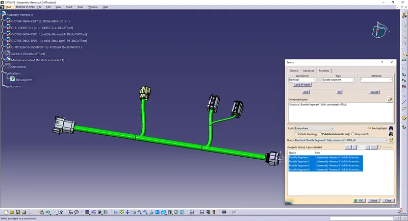
Check the bundle is continuous:
False to show unconnected
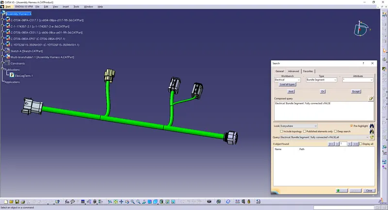
True to show connected
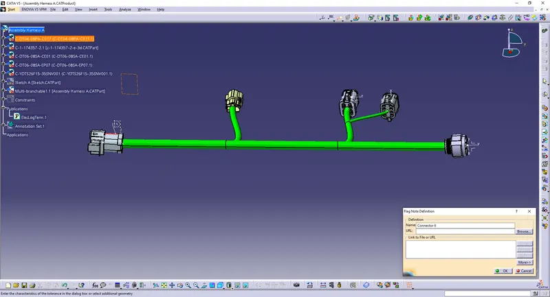
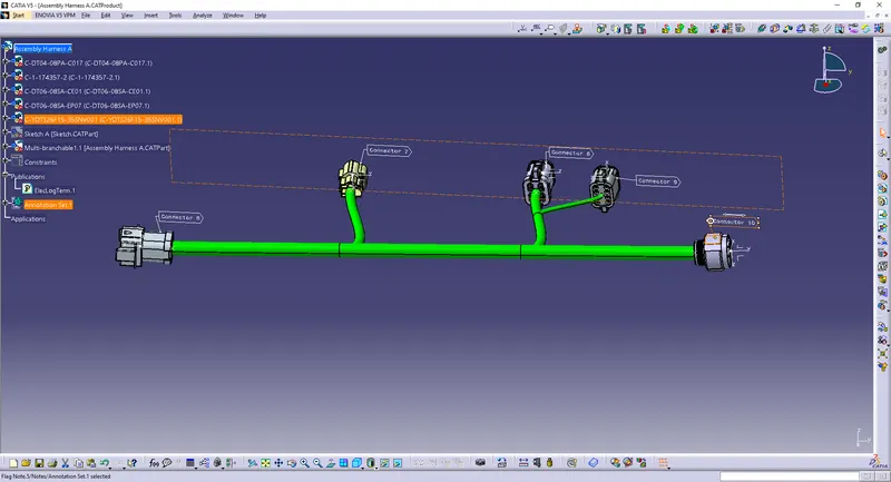
Add annotations:
Create a plane using 'View Creation' option.
Use any note option to annotate the assembly.
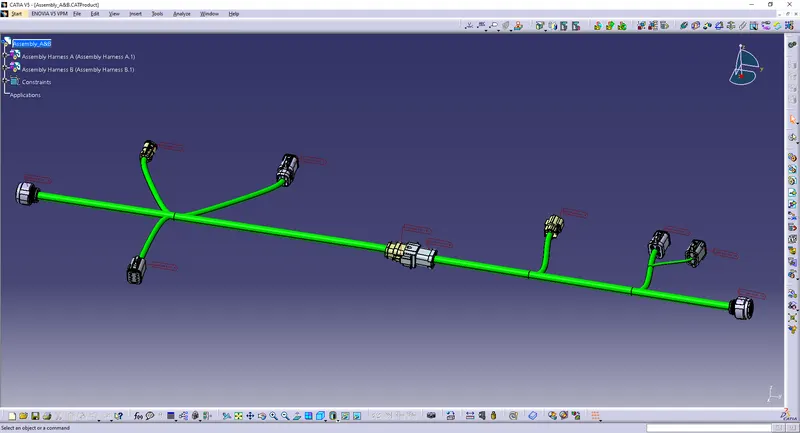
Assembly Harness A & B:
Create a new product file and import the two harness assemblies.
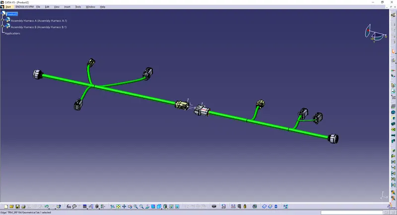
Use 'Connect Electrical Devices' option to connect the two harness assemblies.
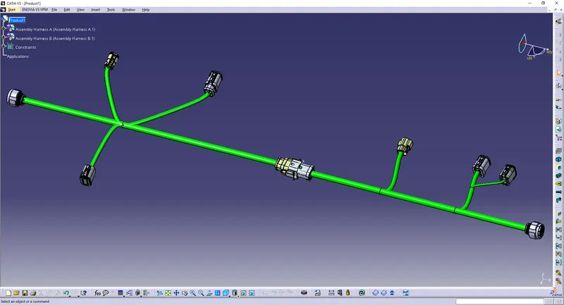
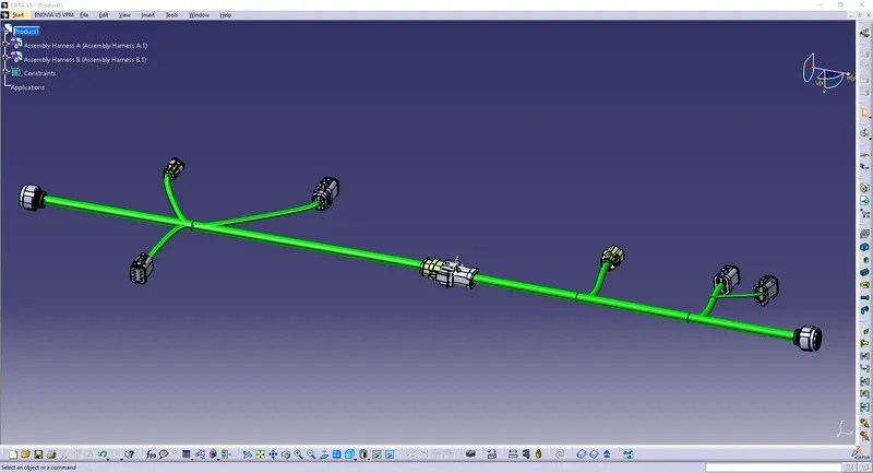
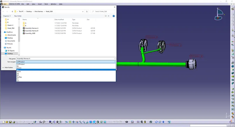
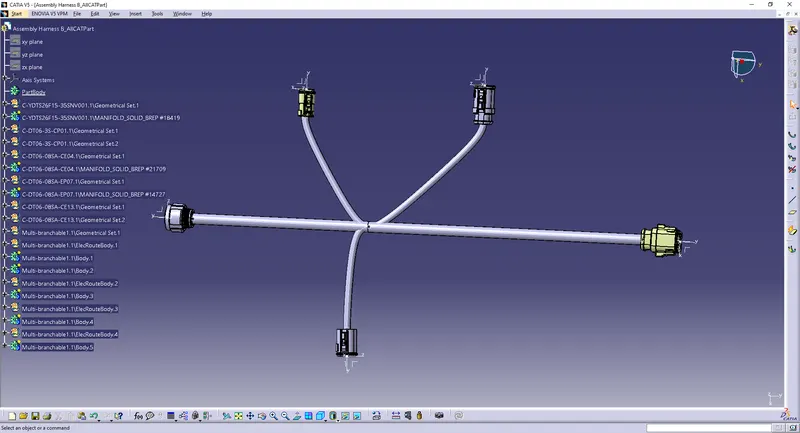
Generate CAT.part of harness assembly and convert it in .igs format:
To save the assemblies into .igs format, Simply save each of the files as .igs in 'Save as type' options.
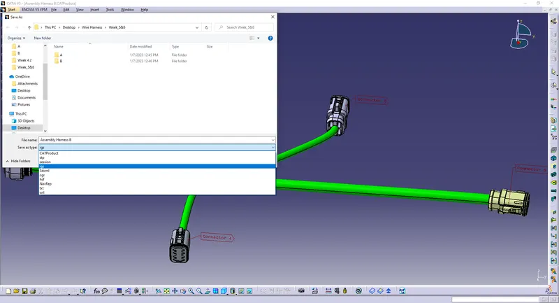
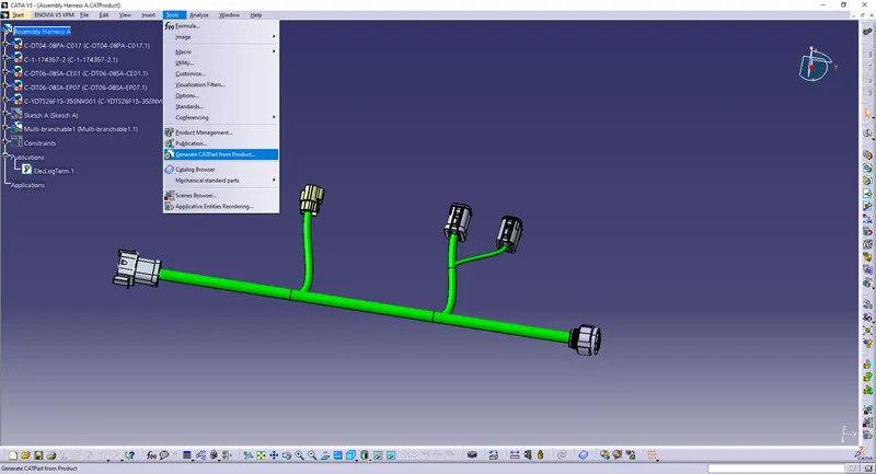
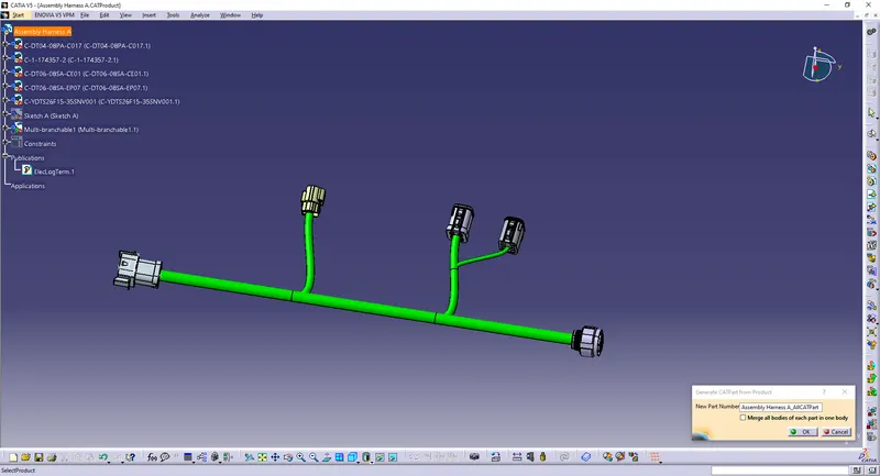
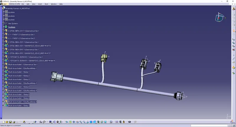
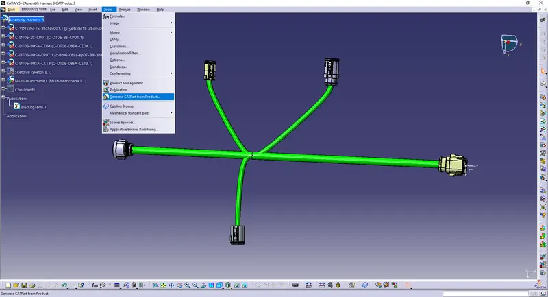
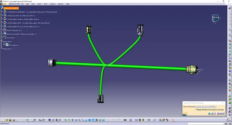
To generate CAT.part of harness assembly:
Go to Tools>>Generate CATpart from Product.
Conclusion:
- All the necessary properties of connectors are defined.
- The bundle continuity is checked.
- Added annotation to all connectors.
- Checked for the bundle warning.
- Generated CAT.part of harness assembly and convert it in .igs format.