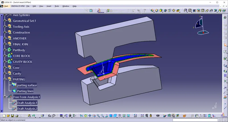
Week 8 - Challenge 6 - Core & Cavity Design
create a tooling axis
- first Class A surface is imported and checked for boundary.
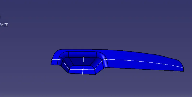
2. Axis is created on the point and intersect line using zyplane and point.
- bisecting line has been created using.
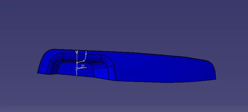
4. on this side there is no part on opposite side.
5. So we created using to normal to the bisecting line at 3 degree.
6. Then using these two line bisecting line is create.
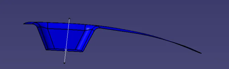
7. This final tooling axis is we get.
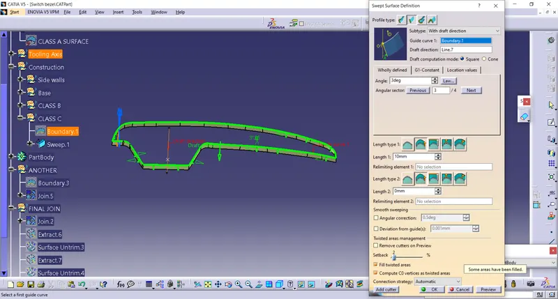
CLASS C
Guiding curve as a boundary of the class A and draft direction is tooling axis with the angle 3 degree
CLASS B
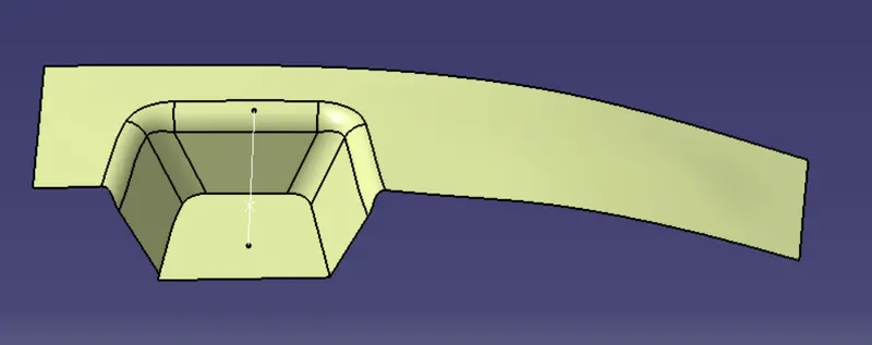
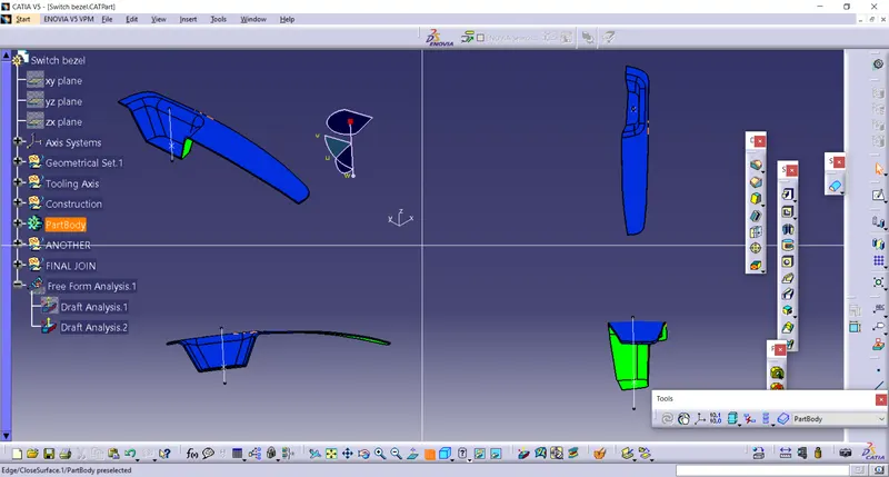
Draft analysis
- Take a compass and placed on the tooling axis and go to featured draft analysis.
- The green colour shows drafting angle 2.9 and above 2.9.
- Red colour indicates the angle zero degree.
- Blue colour indicates the negative draft angle.
CLASS A DRAFT ANALYSIS
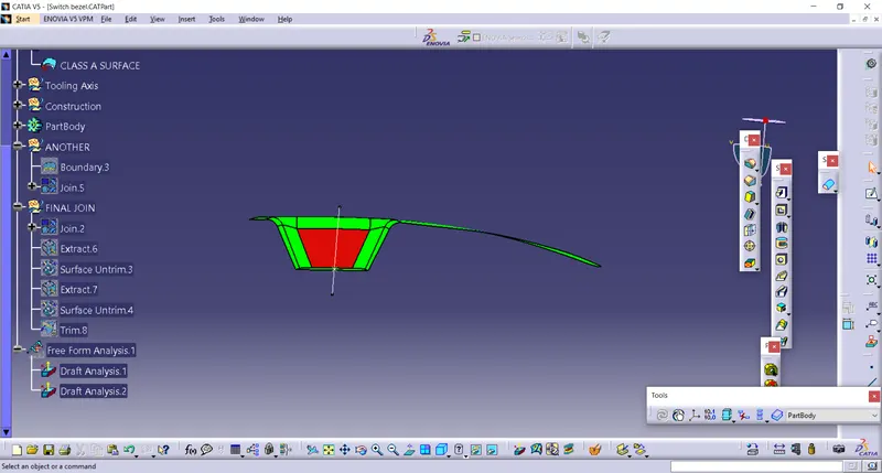
IF we adjust the tooling axis degree then it will show green.
right now it is 3 degree
if we increase in upto 8 degree it will turns into green.
SOLID MODEL.
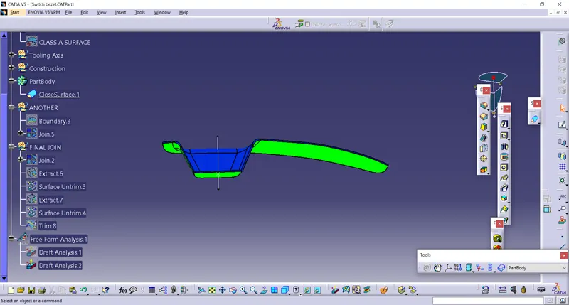
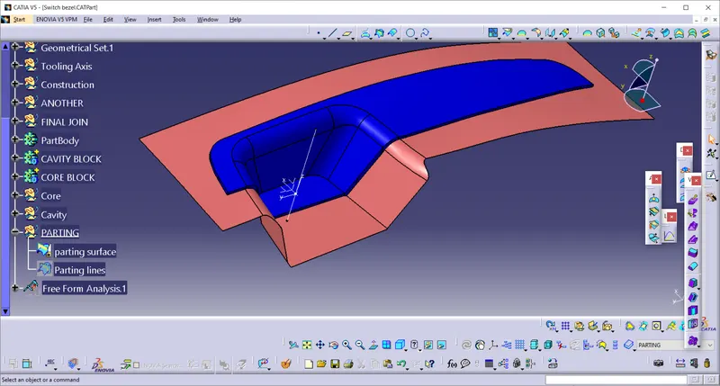
The light pink colour is parting surface
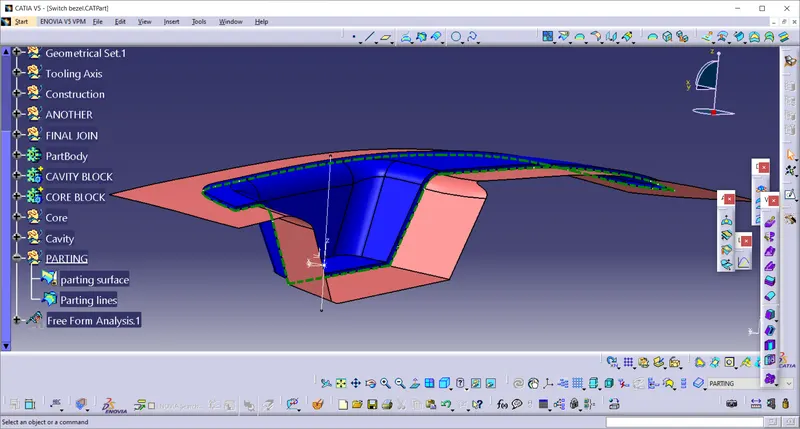
The green colur dootted line is parting line.
cavity block
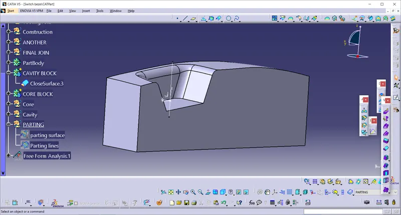
Core block
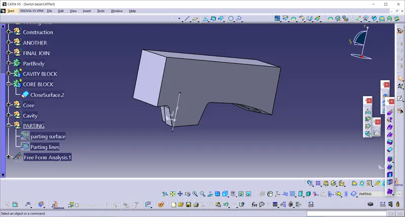
core and cavity combine with parting surface and parting lines