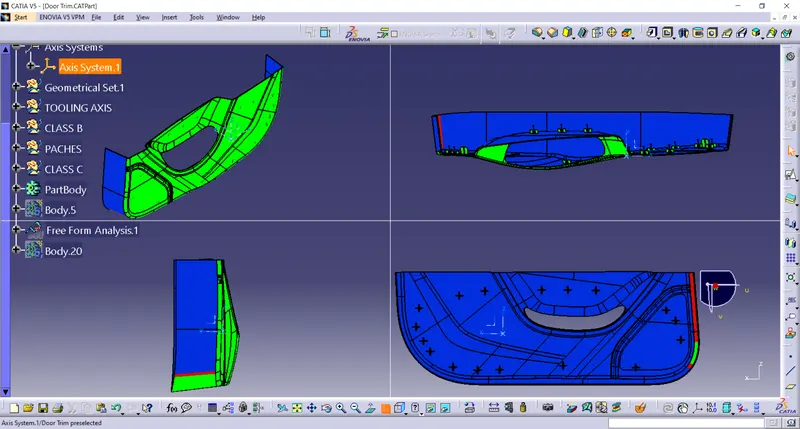
Week 9 - Project 1 - Door Trim Lower with Engineering Features
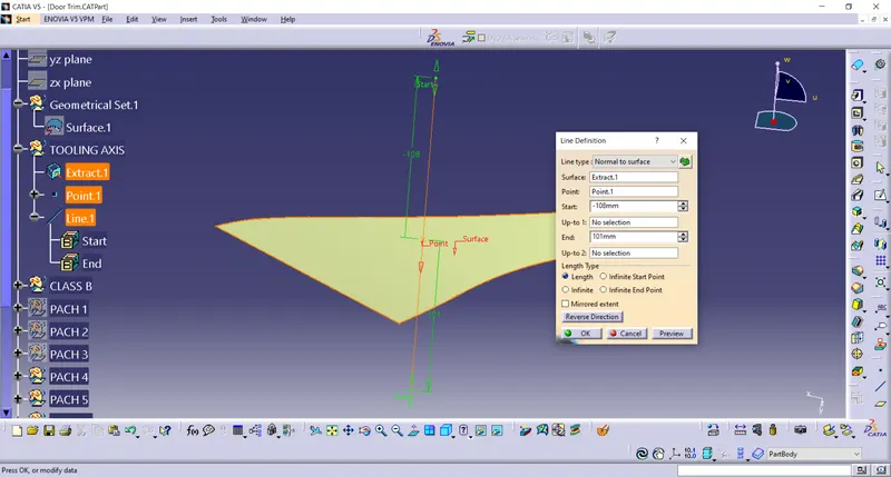
CREATING TOOLING AXIS
1.Extract any surface from the class A.
2. Take a point on that surface and create a line normal to the surface.
CLASS B SURFACE
The Class B surface is created by taking offset of 2.5mm from the Class A
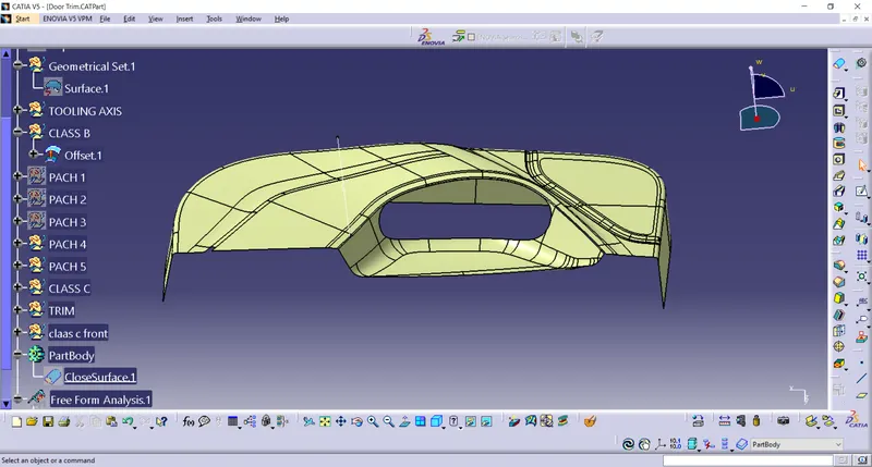
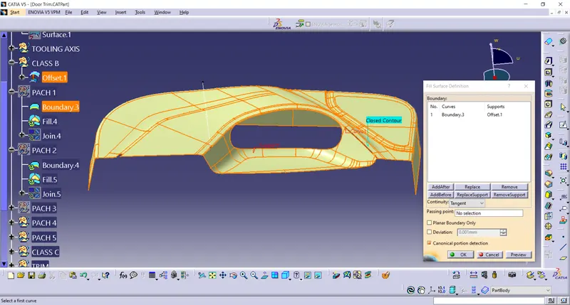
There are some patches is also found during creation.
These patches are fillied by fill command and blend command.
CLASS C
Class c is create with the sweep comand with reference to the surface at 90degree.
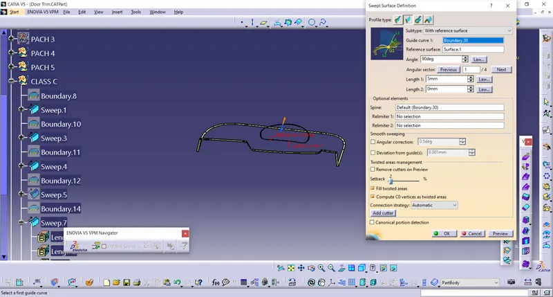
CLASS A, CLASSB, CLASS C
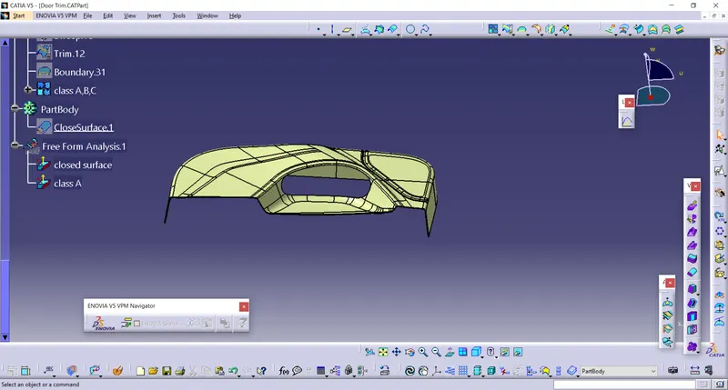
Draft analysis
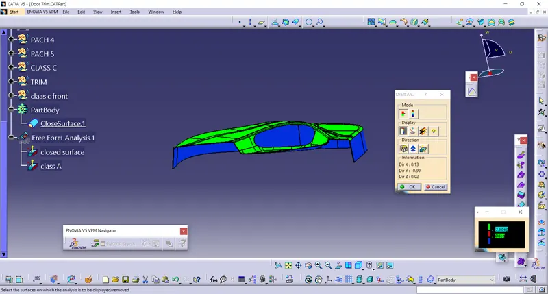
- Take a compass and placed on the tooling axis and go to featured draft analysis.
- The green colour shows drafting angle 2.9 and above 2.9.
- Red colour indicates the angle zero degree.
- Blue colour indicates the negative draft angle.
CLASS A DRAFT ANALYSIS
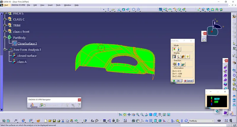
CLOSED SURFACE DRAFT ANALYSIS
Design of heat stakes
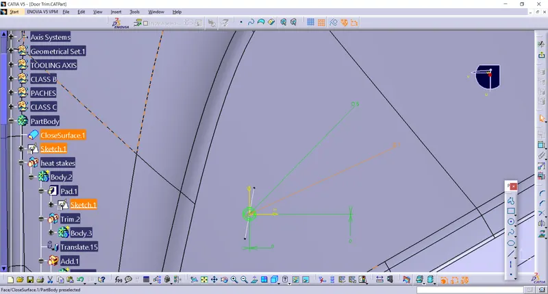
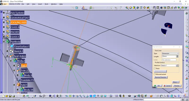
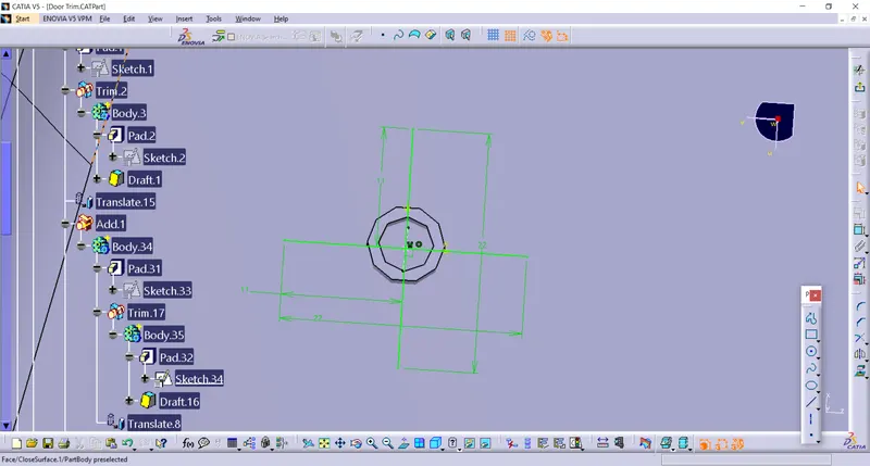
1.The length of the heat steake is taken 22 and the diameter of 7 mm and 5mm.
2. the ribs length is taken 12 mm below than stakes
3. The draft angle of 0.5 degree is given.
4. For the ribs the thickness is 1mm nuetral.
Design of Locators
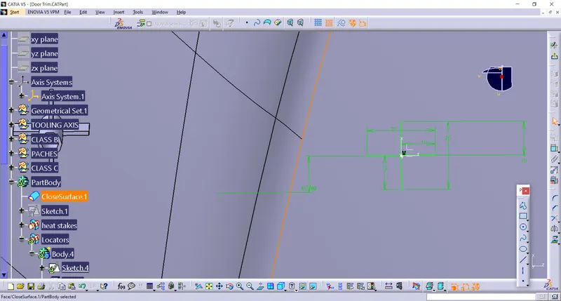
1.The pad length of the Locators is 1mm or 2mm greater than the Heat stakes.
2.The fillets of 025 thickness is given.
3.The 3 mm and 45 degree chamfer is also given.
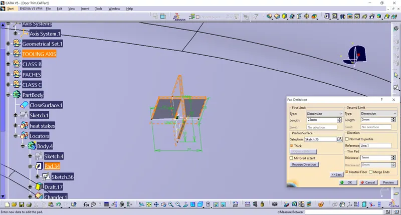
Draft analysis of the Locators and Heat stakes
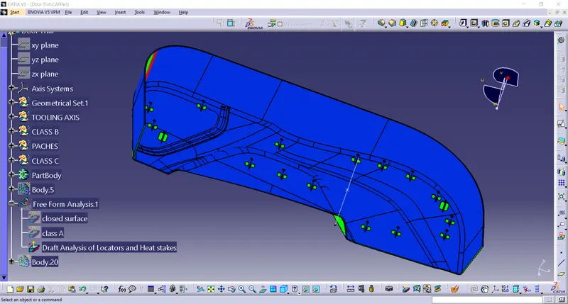
Screenshots of the solid model with the proper color code of the draft angle in various orientations