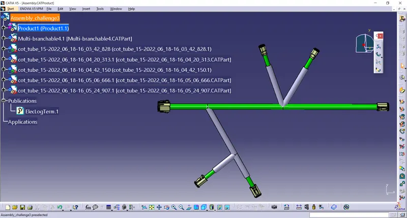
Wiring harness design in CATIA V5 - 3D modeling Week 4 Challenge
Q1. Route the following harness layout in Electrical workbench. Make assumption for harness bundle diameters. Use Following connectors as shown in layout diagram.
Add protective covering on all branches connected to DT06-2S & DT06-4S connectors. Keep end extremity at 30mm (from connectors end)
Download connector 3D data from www.te.com
- DT06-4S
- DT06-6S
- DT06-2S
- DT06-08SA
procedure for defining connector into elctrical part
- Download the connector from the given link.
- Load the connector in mechanical part design and given point and axis by using point definition and axis definition.
- Then go to the elecrical part design and define it as a connector.
- Give bundle point and connector connection point.
procedure to draw sketch
- Go to the file select new and then select part.
- In the part select any plane and draw the sketch by given mesaurement.
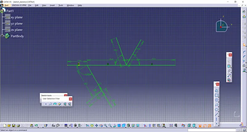
- As shown in the above diagram and save the sketch.
procedure for the elctrical assembly design
- Load all the connector in the elctrical assembly .
- For the manipulation of the connector go to the mechanical assembly design.
- Use the tool manipulation for the proper and required arrangement for the connector.
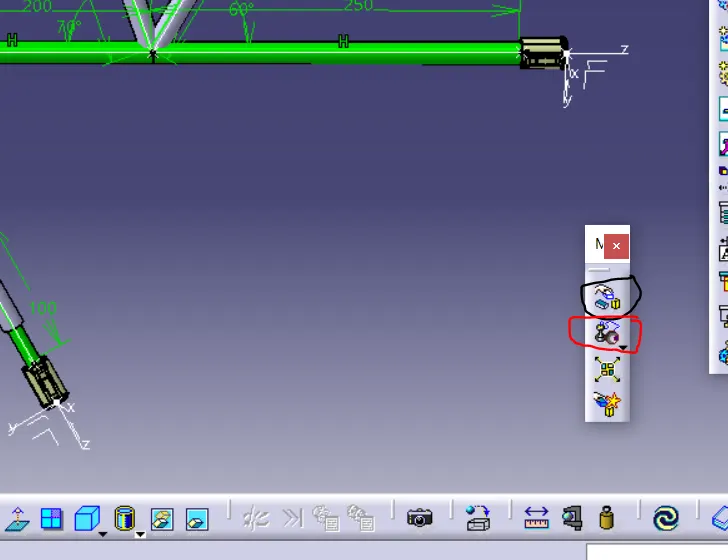
- The black marking is use for the manipulation tool and red marking is use for the snap tool.
- These are the both tool used for the rearrangment of the parts.
procedure for electrical harnees design.
- After doing arrangment go to electrical harness assembly for harness bundle connection.
- In this process the harness is connected to the connector.
- First go to the geometric bundle tool select on that then select on the part name on the tree .
- Now the part is electricaly defined.
- Now go to the bundle segment then select the route definition.
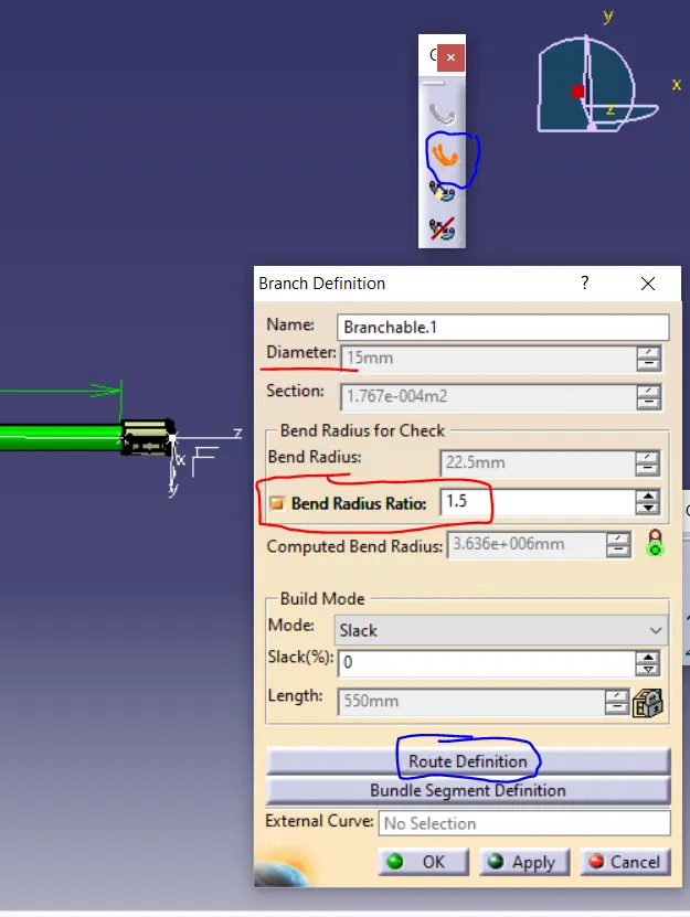
- After that select the connector which have to connect and select ok.
- In that you can define the radius of the harness bundle.
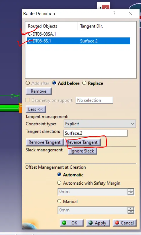
- Above two red tick shows the components is selected by clicking on them.
- Reverse tangent is used to connect the bundle in straight way.
- Branch point is used define point on the branch for the other harness bundle connection.
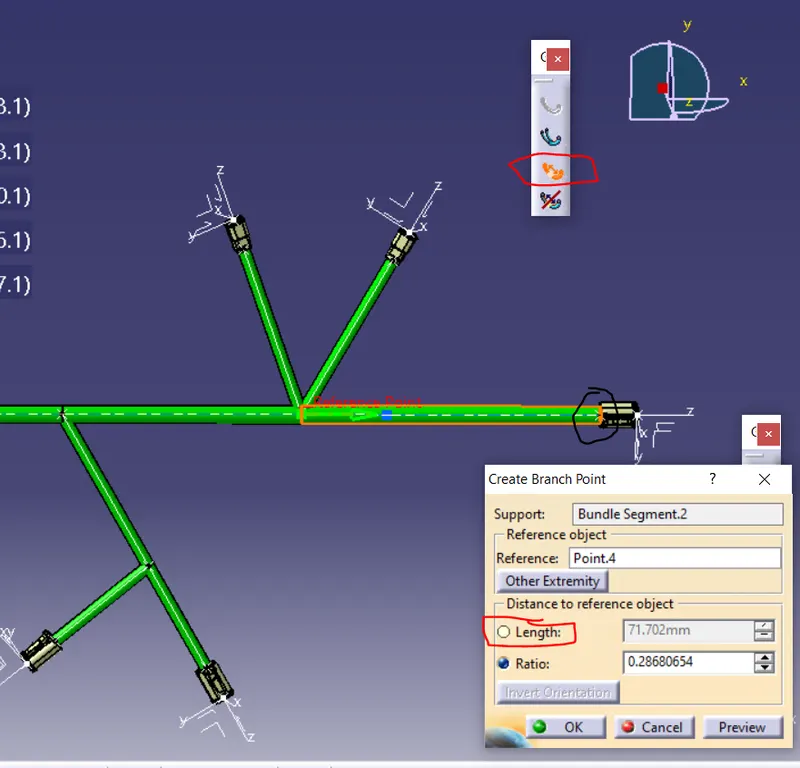
- Above in fig. in the red mark is add branch tool.
- After selecting the tool and click on the point where we need the branch the above pop up will come.
- in that pop we can select the reference point by length or ratio.
- we used the length because it was given.
- Then after doing this select ok the branch point will be created.
- Then for the harness bundle the connector can connect to the branch point and itself.
- Similar ways the harness bundle connection can be done.
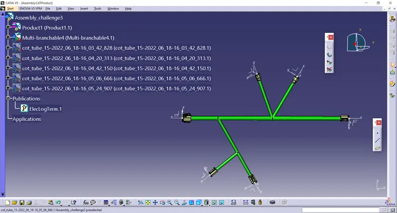
- The above figure shows the harness bunddle connection.
procedure to add protective covering
- Now exit the bundle definition by clicking on the exit shown in below fig.
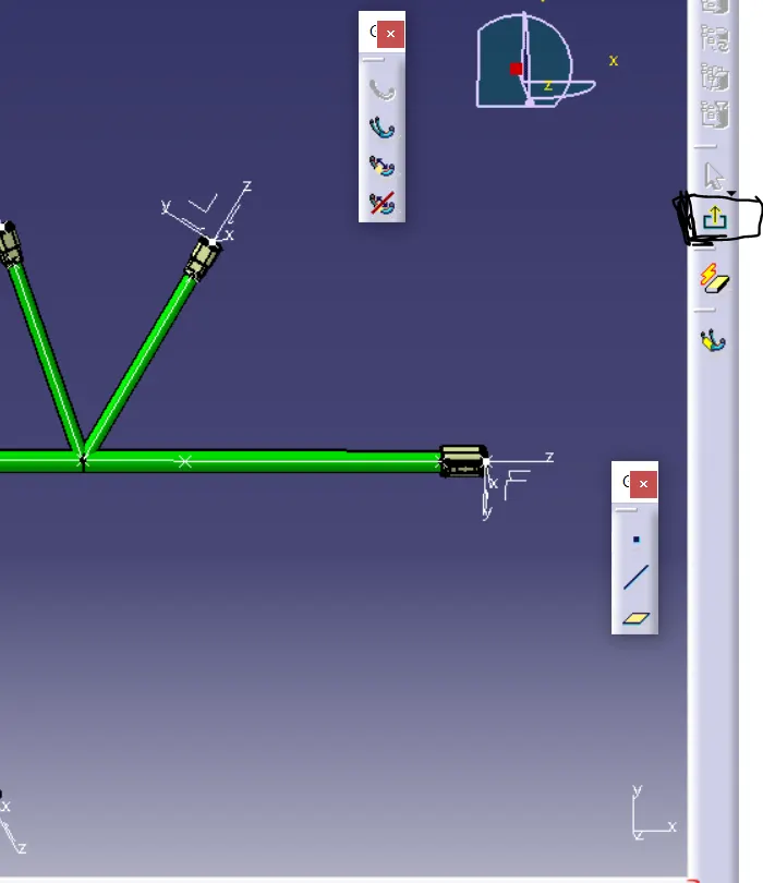
- After doing this you come harness assembly design.
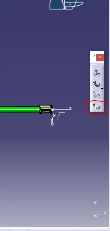
- In red colour marked tool define as add protective .
- By clicking on the tool and then select the harness bundle for the protective covering and add cot tubes .
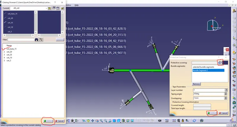
- after the click on the tool right side pop will come after click on the part and then click on the right red colour part.
- After that left side pop up will come in select the cot tube you required.
- We slect the cot 15 tube then select ok.
- The proctive covering will bee add.
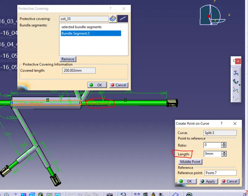
- After that you can give exterimity by clicking on the red colour indicator on the part.
- After that the bottom pop will come.
- In that the length is 30mm is enter aand then click ok the extemity will be given.
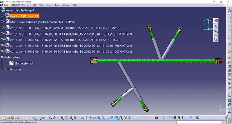
- After adding protective covering.
RESULTS