Week 8 - Challenge 1 - Base Bracket Design
create a tooling axis
- first Class A surface is imported and checked for boundary.
2.Then a duming tooling axis is created. As shown in figure.
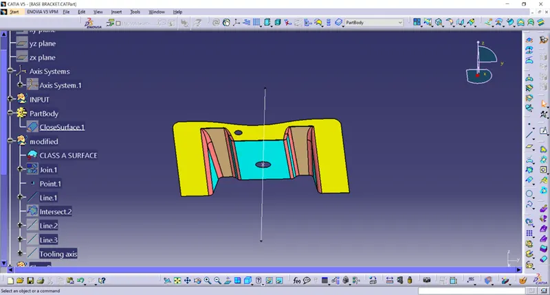
- Axis is created on the point and intersect line using zyplane and point.
- bisecting line has been created using two lines .
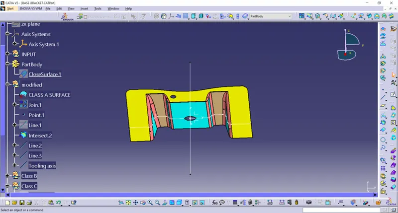
- this bisecting line and line already created in coincide.
- we take this as a tooling axis.
Class B
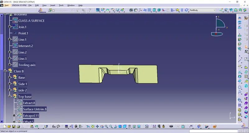
Class C
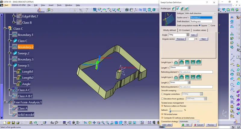
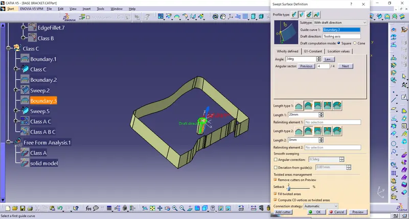
guiding curve as a boundary of the class A and draft direction is tooling axis with the angle 3 degree
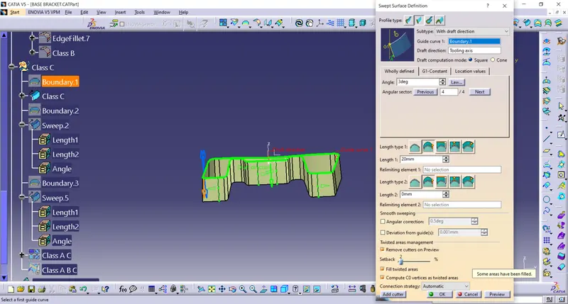
for the hole the direction for the swept is inward fot the both hole.
the angle is 3 degree.
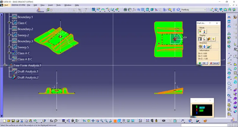
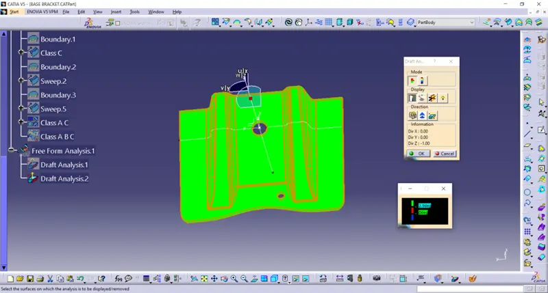
Draft analysis
- Take a compass and placed on the tooling axis and go to featured draft analysis.
- The green colour shows drafting angle 2.9 and above 2.9.
- Red colour indicates the angle zero degree.
- Blue colour indicates the negative draft angle.
Screenshots of the Draft analysis report for the given Class-A surface
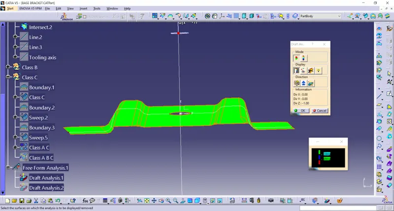
Screenshots of the Draft analysis report for the final plastic component
Screenshots of the solid model with the proper color code of the draft angle in various orientations (Isometric, Front, Side, and Top View)