Wiring harness routing & packaging Rules Week 3 Challenge
harness routing and packaging
procedure to define p clamp as electrical support.
- Download the file from given link.
- P clamp (the link)
- then load the file in mechanical part design.
- for p clamp it has one entry and one exit .
- so define point on both entry and exit by using point defination
- as shown in fig.
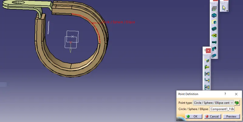
- By using point type circle
- Do this on both side .
- next define the plane on both side.
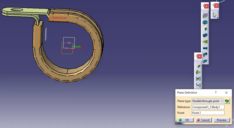
- select plane definition from the tool.
- in that select reeference as body which is highlighting in red on part and select the point that we defined.
- Then select ok . The plane will be created.
- same procedure will be for the exit side also.
- now define plane on bottom side.
- for that go to the plane definition and select offset from plane.
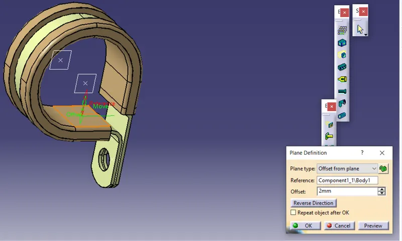
- select reference as bottom surface and take offset of 2mm
- after doing this select ok the plane will be created.
- after this go to the electrical part design to defined as support.
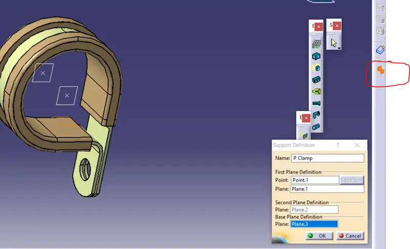
- click on the support denoted as in red part on right side.then select the part and the pop will come as a support definition.
- in that for entry side select point and plane from entry side .
- for second plane definition select opposite plane and for base plane definition select base plane.
- select ok .
- same procedure for the exit side also.
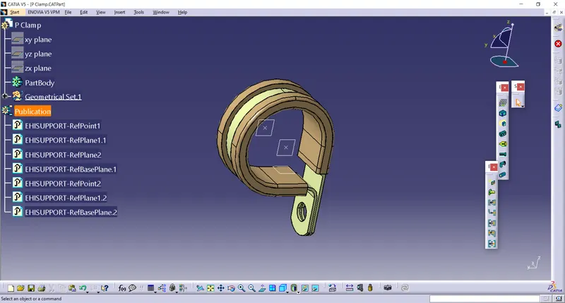
- this is how p clamp is defined as a support.
Result
Q2. Download following Back shell cad data & define it as Electrical back shell using Electrical Part design Workbench. Define all the necessary properties.
procedure of back shell defined as a electrical back shell.
- Download the file from a below link.
- Tyco 1738312-1 https://www.te.com/usa-en/product-1738312-1.html
- Then load the part in mechanical part design.
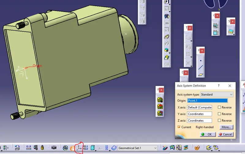
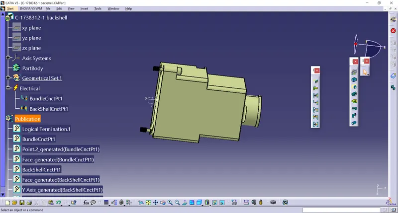
- Give the point and axis.
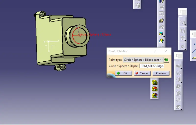
- Generally the round part is consider as a bunddle connection point so, using point definition and selecting point type as circle the point is created.
- On the other side point and axis is created for backshell connection.
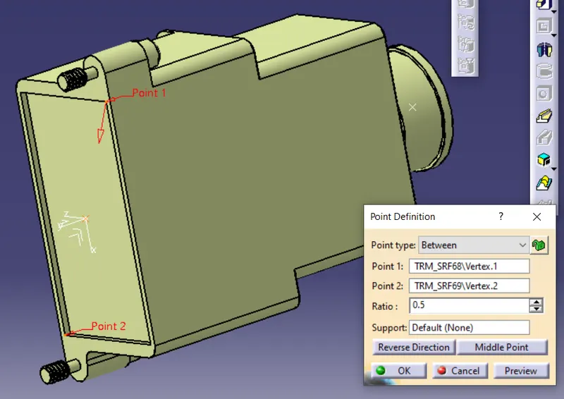
- By using point definition and point type between point is created and by clicked on axis definition the axis is created . as shown in fig.
- now go to the elctrical part design and defined as back shell.
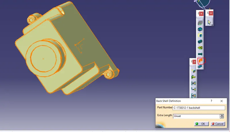
- for that go to the tool on right side there is tool named as define back shell click on that then click on the part.
- then pop up will come as shown in fig. on bottom side select ok.
- Now define bunddle connection for that go to the define bunddle connection tool select on it then select the part.
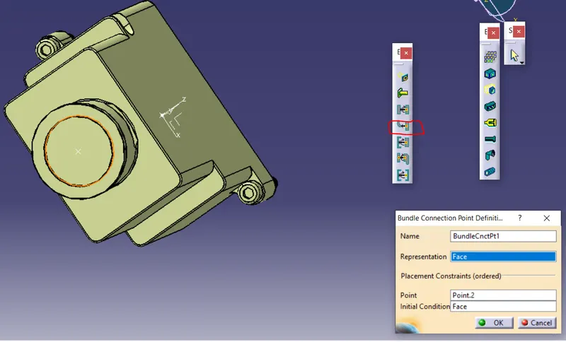
- For representation select the face on which we have created point .
- For placement constraints select the point we have created on circular side
- For initial condition select again the face.
- Then select ok . Now the bunddle connection is made.
- for back shell connection select the define back sheel connection tool.
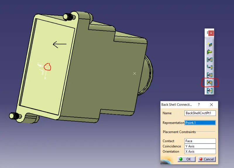
- On the right side on red colour denoted as back shell connection point.
- For representation select point denoted as red circle on the part.
- For contact ,coincidence and orientation select face denoted as black arrow , y-axis and x-axis respectively.
- now click ok . Then part is defined electrically.
Results
Q3. Create Following Corrugated tubes & Add them in Catalogue under “Slit COT” family.
|
Name |
ID (mm) |
OD (mm) |
Thickness (mm) |
|
15mm COT |
12 |
15 |
1.5 |
|
20mm COT |
17 |
20 |
1.5 |
|
35mm COT |
32 |
35 |
1.5 |
|
10mm COT |
7 |
10 |
1.5 |
|
5mm COT |
3 |
5 |
1 |
procedure to create corrugated tubes.
- select on the file go to new and click on the catalogue file.
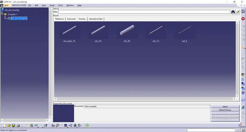
- Then below shown window will open.

- In this window select on add family on right side denoted in red colour.
- after that the family definition pop up will come in that give the name cot_slit and select type 'conduit'.
- conduit is a type select for the corrugated tube.
- now the family is created.
- Now go to the file select new and then select the part.
- Then go to the electrical part design.
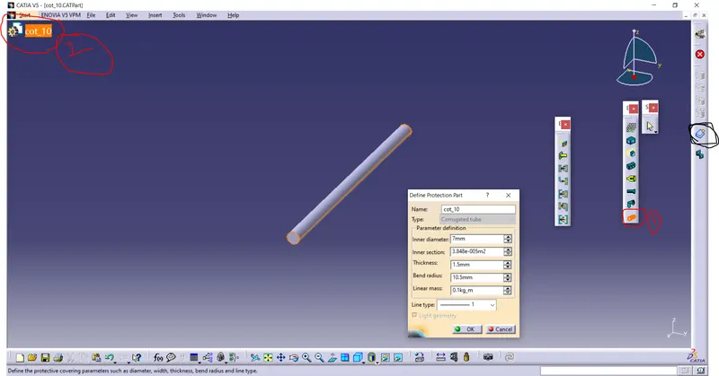
- In elctrical part design first select on the protective covering on right side denoted in red colour.
- Then select on the part name on left top side denoted in red colour
- The pop up will come as the 'Define protection part'
- In that type the name as cot_10 then select the diameter and thickness given for cot_10 in question.
- Bend radius will be the prduct of inner diameter and thickness.
- select ok . The part will be define .
- Then select on the storage device denoted as in black colour.
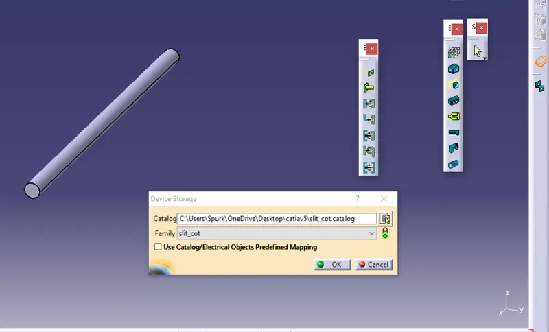
- After selecting that this pop up will come in select the family we created as slit_cot and select ok .
- Now the proctective covering cot_10 is now create and storeed in catalog name slit_cot.
- Similar procedure have to follow for the others.
- only inner diameter and thickness value will vary and other procedure remains same.
Results